Advertisement
Quick Links
Download this manual
See also:
Owner's Manual
Effective : April, 2002
SERVICE MANUAL
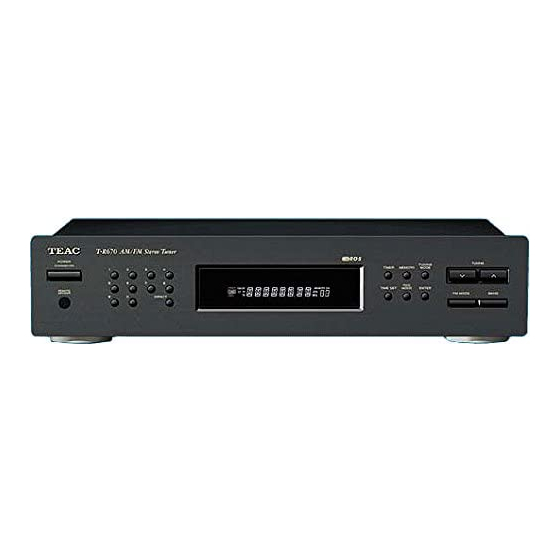
T T - - R R 6 6 7 7 0 0
AM / FM Stereo Tuner
CONTENTS
1 SPECIFICATIONS
2 ADJUSTMENTS AND CHECKS
3 EXPLODED VIEWS AND PARTS LIST
4 PC BOARDS AND PARTS LIST
PC boards shown are viewed from parts side.
●
The parts with no reference number or no parts number in the
●
exploded views are not supplied.
As regards the resistors and capacitors, refer to the circuit diagrams
●
contained in this manual.
£
Parts marked with this sign are safety critical components. They
●
must be replaced with identical components - refer to the appropriate
parts list and ensure exact replacement.
・ ・ ・ ・ ・ ・ ・ ・ ・ ・ ・ ・ ・ ・ ・ ・ ・ ・ ・ ・ ・ ・ ・ ・ ・ ・ ・ ・ ・ ・ ・ ・ ・ ・ ・ ・ ・ ・
・ ・ ・ ・ ・ ・ ・ ・ ・ ・ ・ ・ ・ ・ ・ ・ ・ ・ ・ ・ ・ ・ ・ ・
・ ・ ・ ・ ・ ・ ・ ・ ・ ・ ・ ・ ・ ・ ・ ・ ・
・ ・ ・ ・ ・ ・ ・ ・ ・ ・ ・ ・ ・ ・ ・ ・ ・ ・ ・ ・ ・ ・ ・ ・
NOTES
2
3
6
8
S-0056A
Advertisement

Related Manuals for Teac T-R670


Summary of Contents for Teac T-R670
- Page 1 SERVICE MANUAL T T - - R R 6 6 7 7 0 0 AM / FM Stereo Tuner CONTENTS 1 SPECIFICATIONS ・ ・ ・ ・ ・ ・ ・ ・ ・ ・ ・ ・ ・ ・ ・ ・ ・ ・ ・ ・ ・ ・ ・ ・ ・ ・ ・ ・ ・ ・ ・ ・ ・ ・ ・ ・ ・ ・ 2 ADJUSTMENTS AND CHECKS ・...
-
Page 2: Specifications
1 SPECIFICATIONS FM Tuner Section Voltage Conversion (Without notes 98 MHz, 65 dBf) Tuning Range: 87.5 MHz – 108.0 MHz (100 kHz steps) (General export models only) Usable Sensitivity (IHF): Be sure to remove the power cord from the AC outlet before Mono: 11.2 dBf repositioning the voltage converter switch. -
Page 3: Alignment Instructions
2 ADJUSTMENTS AND CHECKS ALIGNMENT INSTRUCTIONS EQUIPMENT NEEDED: AM Signal Generator FM Signal Generator Oscilloscope VTVM(AC, DC) Test loop antenna (AW Adjustment) Dummy antenna (FM Adjustment) Stereo signal modulator Frequency counter Distortion analyser IMPORTANT 1. Check power-source voltage. 2. Set the function switch to band aligned. 3. - Page 4 1. AM TRACKING VOLTAGE ADJUSTMENTS DC VOLTMETER ......CONNECT TO TEST POINT P5 and GND Band Frequency Adjust for Adjustment 530KHz 2.2V 1720KHz 9.5V TVC1 2. AM RF ADJUSTMENT Signal Generator ......Connects to the AM ANT. Coil through the loop antenna. Adjust for the indication of VTVM of the wave form of scope to be maximum.
- Page 5 4. FM MONO DISTORTION ADJUSTMENT DC VOLT METER ......Connect to TP1(-), TP1(+) Through the choke coll (100 H) Signal Generator......Connect to FM ANT Jack (FM IN) through the dummy. Distortion Meter ......Connect to the output. Frequency Adjust for Adjustment 97.8MHz DC Voltmeter 0V T3-1 TP1(-)
- Page 6 3 EXPLODED VIEWS AND PARTS LIST −6−...
- Page 7 EXPLODED VIEW LIST REF.NO. PARTS NO. DESCRIPTION REMARKS 9A09229700 FACE PLATE 75L837W0248* 9A09230500 WASHER,POWER KNOB 85A637****** 9A09231000 WASHER 85A638****** 9A09230400 POWER KNOB 80KB431***** 9A09230300 ACRY 85A398****** 9A09230600 PUSH KNOB 80KB432***** 9A09230200 ACRY 85A636****** 9A09230700 PUSH KNOB 80KB433***** 9A09230800 PUSH KNOB 80KB434***** 9A09230900 PUSH KNOB...
- Page 8 4 PC BOARDS AND PARTS LIST MAIN PCB TRANSFORMER PCB SELECT SW PCB KEY PCB −8−...
- Page 9 MAIN PCB ASSY MAIN PCB ASSY REF.NO. PARTS NO. DESCRIPTION REF.NO. PARTS NO. DESCRIPTION £ 9A09242400 9A09233300 MAIN PCB ASSY IC,AN7812 9A09245200 PCB,B3850/B3852/B3853 9A09244300 HEAT SINK £ 9A09241800 C,ELEC 2200UF/25V VD1,VD2 9A09243600 VARICAP,1SV149 £ 9A09240000 C,ELEC 100UF/100V 9A09243700 CRYSTAL,7.2MHZ £ 9A09240300 C,ELEC 47UF/63V NP 9A09243800 CERAMIC FILTER,SFZ10.7MS2...
- Page 10 T-R670 SCHEMATIC DIAGRAM MAIN PCB, TRANSFORMER PCB, SELECT SW PCB T T - - R R 6 6 7 7 0 0 INSTRUCTIONS FOR SERVICE PERSONNEL BEFORE RETURNING APPLIANCE TO THE CUSTOMER, MAKE LEAKAGE- CURRENT OR RESISTANCE MEASUREMENTS TO DETERMINE THAT EXPOSED AM/FM Stereo Tuner PARTS ARE ACCEPTABLY INSULATED FROM THE SUPPLY CIRCUIT.
- Page 11 T-R670 SCHEMATIC DIAGRAM KEY PCB T T - - R R 6 6 7 7 0 0 AM/FM Stereo Tuner 1 st Issue; October 2001...
Need help?
Do you have a question about the T-R670 and is the answer not in the manual?
Questions and answers