Advertisement
Quick Links
Effective : December, 2002
SERVICE MANUAL
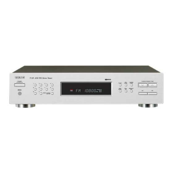
T T - - 1 1 D D
CONTENTS
1 SPECIFICATIONS
2 ADJUSTMENTS AND CHECKS
3 EXPLODED VIEWS AND PARTS LIST
4 PC BOARDS AND PARTS LIST
PC boards shown are viewed from parts side.
●
The parts with no reference number or no parts number in the
●
exploded views are not supplied.
As regards the resistors and capacitors, refer to the circuit diagrams
●
contained in this manual.
£
Parts marked with this sign are safety critical components. They
●
must be replaced with identical components - refer to the appropriate
parts list and ensure exact replacement.
AM/FM Stereo Tuner
・ ・ ・ ・ ・ ・ ・ ・ ・ ・ ・ ・ ・ ・ ・ ・ ・ ・ ・ ・ ・ ・ ・ ・ ・ ・ ・ ・ ・ ・ ・ ・ ・ ・ ・ ・ ・ ・
・ ・ ・ ・ ・ ・ ・ ・ ・ ・ ・ ・ ・ ・ ・ ・ ・ ・ ・ ・ ・ ・ ・ ・
・ ・ ・ ・ ・ ・ ・ ・ ・ ・ ・ ・ ・ ・ ・ ・ ・
・ ・ ・ ・ ・ ・ ・ ・ ・ ・ ・ ・ ・ ・ ・ ・ ・ ・ ・ ・ ・ ・ ・ ・
NOTES
2
3
6
8
S-0075A
Advertisement

Related Manuals for Teac T-1D


Summary of Contents for Teac T-1D
- Page 1 SERVICE MANUAL T T - - 1 1 D D AM/FM Stereo Tuner CONTENTS 1 SPECIFICATIONS ・ ・ ・ ・ ・ ・ ・ ・ ・ ・ ・ ・ ・ ・ ・ ・ ・ ・ ・ ・ ・ ・ ・ ・ ・ ・ ・ ・ ・ ・ ・ ・ ・ ・ ・ ・ ・ ・ 2 ADJUSTMENTS AND CHECKS ・...
-
Page 2: Specifications
1 SPECIFICATIONS FM Tuner Section (Without notes 98 MHz, 65 dBf) Tuning Range: 87.5 MHz – 108.0 MHz (50 kHz steps) Usable Sensitivity (IHF): Mono: 11.2 dBf 50 dB Quieting Sensitivity: Mono: 15 dBf Stereo: 20 dBf Total Harmonic Distortion (1 kHz): Mono: 0.4% Stereo: 0.5% Frequency Response: 30 Hz –... -
Page 3: Alignment Instructions
2 ADJUSTMENTS AND CHECKS ALIGNMENT INSTRUCTIONS EQUIPMENT NEEDED: AM Signal Generator FM Signal Generator Oscilloscope VTVM(AC, DC) Test loop antenna (AW Adjustment) Dummy antenna (FM Adjustment) Stereo signal modulator Frequency counter Distortion analyser IMPORTANT 1. Check power-source voltage. 2. Set the function switch to band aligned. 3. - Page 4 1. AM TRACKING VOLTAGE ADJUSTMENTS DC VOLTMETER ......CONNECT TO TEST POINT P5 and GND Band Frequency Adjust for Adjustment 603KHz 2.2V 1620KHz 9.0V TVC1 2. AM RF ADJUSTMENT Signal Generator ......Connects to the AM ANT. Coil through the loop antenna. Adjust for the indication of VTVM of the wave form of scope to be maximum.
- Page 5 4. FM MONO DISTORTION ADJUSTMENT DC VOLT METER ......Connect to TP1(-), TP1(+) Through the choke coll (100 H) Signal Generator......Connect to FM ANT Jack (FM IN) through the dummy. Distortion Meter ......Connect to the output. Frequency Adjust for Adjustment 97.8MHz DC Voltmeter 0V T3-1 TP1(-)
- Page 6 3 EXPLODED VIEWS AND PARTS LIST −6−...
- Page 7 EXPLODED VIEW LIST REF.NO. PARTS NO. DESCRIPTION REMARKS 9A09523500 FACE PLATE 75L950W0269* 9A09503000 WASHER,POWER 85A716****** 9A09524400 WASHER 85A717****** 9A09523900 KNOB,POWER PUSH 80KB456***** 9A09230300 ACRY 85A398****** 9A09524000 KNOB,PUSH 11P 80KB457***** 9A09230200 ACRY 85A636****** 9A09524100 KNOB,PUSH 6P 80KB458***** 9A09524200 KNOB,PUSH 80KB459***** 9A09524300 KNOB,PUSH 80KB460***** 9A09523600...
- Page 8 4 PC BOARDS AND PARTS LIST B4230/B4231 PCB B3850 PCB B3852 PCB −8−...
- Page 9 KEY PCB ASSY TUNER PCB ASSY REF.NO. PARTS NO. DESCRIPTION REF.NO. PARTS NO. DESCRIPTION 9A09525250 KEY PCB ASSY B4230 J8,J10 9A09244800 WAFER,5045-2P 9A09529500 KEY PCB B4230 9A09526000 ANT TERMINAL 9A09529300 CONNECTOR,ED-G14 2P 9A09242600 CHOKE,2.2UH 9A09529400 CONNECTOR,ED-G15 2P 9A09242800 I.F.T,LA-003 D1,D2 9A09237300 DIODE,1N4148 9A09244600...
- Page 10 POWER PCB ASSY REF.NO. PARTS NO. DESCRIPTION 9A09525150 POWER PCB ASSY B3852 9A09245200 PCB,B3850/B3852/B3853 9A09527900 KIT,B3582 9A09241200 FUSE HOLDER J5 TO J4 9A09245600 CONNECTOR,ED-488 6P 9A09245400 WAFER,3963-3P2T £ 9A09245500 TRANSFORMER −10−...
- Page 11 T-1D SCHEMATIC DIAGRAM T T - - 1 1 D D AM/FM Stereo Tuner 1 st Issue; August 2002...
- Page 12 T-1D SCHEMATIC DIAGRAM T T - - 1 1 D D AM/FM Stereo Tuner 1 st Issue; August 2002...
Need help?
Do you have a question about the T-1D and is the answer not in the manual?
Questions and answers