Intel SDS2 Product Manual
Hide thumbs
Also See for SDS2:
- Parts list (8 pages) ,
- Quick start manual (2 pages) ,
- Specification (145 pages)

Related Manuals for Intel SDS2


Summary of Contents for Intel SDS2
- Page 1 ® Intel Server Board SDS2 Product Guide ® A Guide for Technically Qualified Assemblers of Intel Identified Subassemblies/Products Order Number: A58836-002...
- Page 2 No license, express or implied, by estoppel or otherwise, to any intellectual property rights is granted by this document. Except as provided in Intel's Terms and Conditions of Sale for such products, Intel assumes no liability whatsoever, and Intel disclaims any express or implied warranty, relating to sale and/or use of Intel products including liability or warranties relating to fitness for a particular purpose, merchantability, or infringement of any patent, copyright or other intellectual property right.
-
Page 3: Table Of Contents
Installing the Server Board .....................27 Making Connections to the Server Board...............28 Cable Routing .........................29 Installing the COM2 Cable ....................30 Finishing Up ........................31 ® Getting Started with Intel Server Management (Optional) ...........32 3 Upgrading Tools and Supplies Needed.....................35 Cautions ...........................35 Memory ............................36... - Page 4 Using the Firmware Update Utility...................70 Making a BMC Firmware Update Diskette ..............70 Updating the BMC Firmware ..................70 Recovering the BMC Firmware ..................71 Updating the FRU/SDR Files....................71 Making a FRU/SDR File Update Diskette ..............71 Updating the FRU/SDR Files..................71 Intel Server Board SDS2 Product Guide...
- Page 5 Using the Adaptec SCSI Utility ....................72 Running the SCSI Utility ....................72 5 Solving Problems Resetting the System.......................73 Initial System Startup .......................73 Checklist..........................73 Running New Application Software ..................74 Checklist..........................74 After the System Has Been Running Correctly ...............74 Checklist..........................74 More Problem Solving Procedures ..................75 Preparing the System for Diagnostic Testing..............75 Monitoring POST ......................75 Verifying Proper Operation of Key System Lights............75...
- Page 6 Server Board Features......................1 Video Modes ........................6 Software Security Features ....................12 Configuration Utilities ......................45 Hot Keys ........................45 Configuration Jumper (CN42)..................83 Configuration Jumper (CN46)..................84 Configuration Jumper (CN47)..................84 Configuration Jumper (CN48)..................84 10. Configuration Jumper (CN49)..................84 11. Configuration Jumper (CN50)..................84 Intel Server Board SDS2 Product Guide...
-
Page 7: Description
AIC-7899W dual channel Ultra160 SCSI, supporting onboard Ultra (LVD) wide, Ultra-wide, and Ultra160 SCSI interfaces. ® Network Integrated onboard NICs, an Intel 82550 single chip PCI LAN controller for 10 or 100 MbpsTX Fast Ethernet networks. Two RJ-45 Ethernet connectors at the I/O back panel. -
Page 8: Back Panel Connectors
Back Panel Connectors Figure 1. Back Panel Connectors Intel Server Board SDS2 Product Guide... -
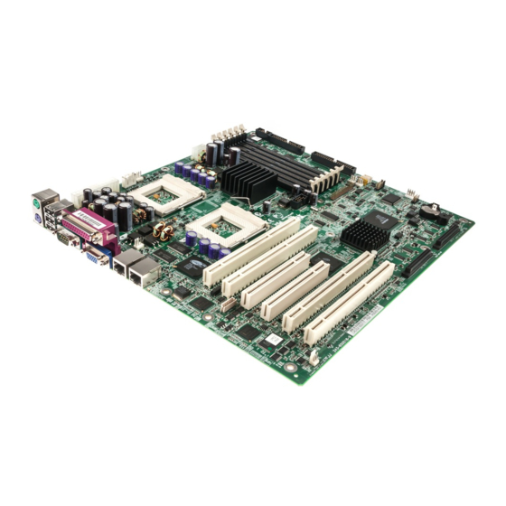
Page 9: Server Board Connector And Component Locations
Server Board Connector and Component Locations Chassis intrusion connector N. Floppy drive connector CPU Fan 2 O. IDE Back panel I/O ports Fan 2 Fan 4 Q. Fan 1 Fan 3 R. Configuration jumper block CN42 Main power connector Configuration jumper block CN46-CN49 CPU Fan 1 Battery CPU 1... -
Page 10: Processor
The SDS2 Server Board contains six 168-pin DIMM sockets. Memory is partitioned as three banks. DIMMs must be populated in identical pairs. The SDS2 server board supports up to six 3.3-V, registered ECC SDRAM DIMMs that are compliant with the JEDEC PC133 specification. A wide range of DIMM sizes are supported, including 64 MB, 128 MB, 256 MB, 512 MB, and 1 GB DIMMs. -
Page 11: Add-In Board Slots
Add-in Board Slots The server board has two full-length standard PCI (PCI-33/32 bit) connectors. PCI features: • Bus speed up to 33 MHz • 32 bit memory addressing • 5 V signaling environment • Burst transfers of up to 133 Mbps •... -
Page 12: Video
The embedded Adaptec AIC-7899W dual function SCSI controller provides Ultra160 (LVDS), (Ultra 2), and Ultra wide (SE) SCSI interfaces as two independent PCI functions. The SDS2 baseboard provides active terminators, termination voltage, resetable fuse, and protection diode for both SCSI channels. Onboard terminators can be enabled/disabled using the BIOS setup menu. -
Page 13: Ide Controller
Up to two devices USB Interface The SDS2 Server Board provides three external USB connectors on the rear I/O panel. The external connectors are defined by the USB Specification, Revision 1.1. One additional USB connector is supported internally through a 10-pin header on the server board that can be cabled to a front panel board. -
Page 14: Network Controller
The server board includes a 10BASE-T/100BASE-TX network solution based on the Intel 82550 single chip Fast Ethernet PCI Bus Controller. As a PCI bus master, the controller can burst data at up to 132 MB/s. The controller contains two receive and transmit FIFO buffers that prevent data overruns or underruns while waiting for access to the PCI bus. - Page 15 Adapter Fault Tolerance Adapter Fault Tolerance (AFT) is a simple, effective, and fail-safe approach to increase the reliability of server connections. AFT gives you the ability to set up link recovery to the server adapter in case of a cable, port, or network interface card failure. By assigning two PRO/100 Intelligent Server adapters as a team, AFT enables you to maintain uninterrupted network performance.
-
Page 16: Keyboard And Mouse
ACPI The SDS2 supports the Advanced Configuration and Power Interface (ACPI) as defined by the ACPI 1.0b. An ACPI aware operating system can put the system into a state where the hard drives spin down, the system fans stop, and all processing is halted. -
Page 17: Software Locks
Software Locks The BIOS Setup and the System Setup Utility (SSU) provide a number of security features to prevent unauthorized or accidental access to the system. Once the security measures are enabled, you can access the system only after you enter the correct password(s). For example: •... -
Page 18: Software Security Features
In secure mode, the server will not boot from or write to a diskette unless a password is entered. To write protect access to diskette whether the server is in secure mode or not, use the Setup main menu, Floppy Options, and specify Floppy Access as read only. continued Intel Server Board SDS2 Product Guide... - Page 19 Table 3. Software Security Features (continued) Feature Description Set a time out period so Specify and enable an inactivity time out period of from 1 to 120 minutes. that keyboard and mouse If no keyboard or mouse action occurs for the specified period, attempted input are not accepted keyboard and mouse input will not be accepted.
- Page 20 Intel Server Board SDS2 Product Guide...
-
Page 21: Server Board Installation
To ensure EMC compliance with your local regional rules and regulations, the final configuration of your end system product may require additional EMC compliance testing. For more information please contact your local Intel Representative. See “Regulatory and Integration Information” on page 85 for product Safety and EMC regulatory compliance information. -
Page 22: Safety And Regulatory Compliance
To avoid integration difficulties and possible board damage, your system must meet the following minimum requirements. For a list of qualified memory and chassis components see: http://support.intel.com/support/motherboards/server/SDS2 Processor Minimum of one 1.0 GHz Intel Pentium III processor with 256 cache support. For a complete list of supported processors, see: http://support.intel.com/support/motherboards/server/SDS2 Memory Minimum of two identical 3.3 V, ECC, PC/133 compliant, registered SDRAM, 168-pin gold... -
Page 23: Installation Notes
Installation Notes Installation Process Quick Reference Step Where the information is located Install the primary processor This guide Install the secondary processor (optional) This guide Install memory This guide Remove the access cover Your chassis manual Install the I/O shield This guide Rearrange the standoffs This guide... -
Page 24: Attaching The Gasket To The I/O Shield
Attaching the Label to the I/O Shield 1. Remove the backing from the label included with your server board. 2. Press the label onto the outside face of the I/O shield. Figure 4. Attaching the Label to the I/O Shield Intel Server Board SDS2 Product Guide... -
Page 25: Installing The I/O Shield
Installing the I/O Shield 1. Position one edge so that the dotted groove is outside the chassis wall, and the lip of the shield rests on the inner chassis wall. 2. Hold the shield in place, and push it into the opening until it is seated. Make sure the I/O shield snaps into place all the way around. -
Page 26: Installing The Processor(S)
Secondary Processor Socket (CPU2). If you are adding a second processor to your system, you must verify that the second processor is identical to the first Intel Pentium III, same voltage and speed. This server board has “zero-insertion-force” sockets. If processor does not drop easily into socket holes, make sure the lever is in the full-upright position. -
Page 27: Inserting The Processor
3. Align the pins of the processor with the socket as shown in Figure 5, and insert the processor into the socket. Lower the locking bar completely. Figure 7. Inserting the Processor Server Board Installation... -
Page 28: Attaching The Heat Sink And Retention Clip
(see 2 below). Align the notched side of the heat sink (see 2 below) with the edge of the socket containing the “PG370” designation (see 3 below) and place onto the processor as shown. Figure 8. Attaching the Heat Sink and Retention Clip Intel Server Board SDS2 Product Guide... -
Page 29: Locking The Heat Sink Retention Clip
5. Close the heat sink retention clip as shown. Use slow, constant pressure to close the retention clip lever. Figure 9. Locking the Heat Sink Retention Clip 6. Attach the fan heat sink clip to the processor socket as shown. Figure 10. -
Page 30: Installing Memory
The SDS2 Server Board contains six 168-pin DIMMs. Memory is partitioned as three banks. DIMMs must be populated in identical pairs. The SDS2 server board supports up to six 3.3-V, registered ECC SDRAM DIMMs that are compliant with the JEDEC PC133 specification. A wide range of DIMM sizes are supported, including 64 MB, 128 MB, 256 MB, 512 MB, and 1 GB DIMMs. -
Page 31: Installing Memory
NOTE Use DIMMs that have been tested for compatibility with the server board. Contact your sales representative or dealer for a current list of approved memory modules. Check the Intel Customer Support website for the latest tested memory list: http://support.intel.com/support/motherboards/server/SDS2 1. -
Page 32: Configuring Chassis Standoffs
For the Intel SC5100 chassis: 1. Install standoffs in positions 7 and 17. Standoff numbering in other chassis may be different. Standoffs are included with your chassis. Figure 13. Configuring Chassis Standoffs Intel Server Board SDS2 Product Guide... -
Page 33: Installing The Server Board
Installing the Server Board 1. Place the board into the chassis, making sure that the back panel I/O shield openings and chassis standoffs align correctly. 2. Attach the board with the screws included with your chassis. Figure 14. Placing the Server Board in the Chassis Server Board Installation... -
Page 34: Making Connections To The Server Board
Chassis Fans D. Floppy disk drive connector CPU1 Fan ATA 100/IDE Chassis Fans COM2/EMP Front Panel connector M. Chassis Intrusion G. SCSI B N. Chassis Fans Figure 15. Making Connections to the Server Board Intel Server Board SDS2 Product Guide... -
Page 35: Cable Routing
Cable Routing To ensure proper air flow within the chassis, follow the cable routing guidelines below. IDE or SCSI Cables Cables that connect to devices in the lower device bays should be routed around the epac as shown below. 1. Route cables as shown. 2. -
Page 36: Installing The Com2 Cable
2. Attach the other end of the COM2 connector located on your server board between the CPU2 Processor socket and the DIMMs. See “Making Connections to the Server Board” on page 28 for the exact COM2 connector location. Figure 18. Installing the COM2 Cable Intel Server Board SDS2 Product Guide... -
Page 37: Finishing Up
Finishing Up WARNING An electrical shock hazard exists if the chassis cover is not replaced before connecting the chassis AC power. 1. Install the chassis cover according to the instructions for your chassis. 2. See your chassis documentation to complete rack or pedestal installation. 3. -
Page 38: Getting Started With Intel Server Management (Optional)
Remote access is provided through either a modem or network connection. To get started with Intel Server Management, you install the Service Partition first, then the system’s operating system, and finally Intel Server Control. The information here describes installation on a system running a Microsoft Windows operating system. - Page 39 Installing Intel Server Control 1. Insert the Intel Server Board SDS2 Resource CD into the system’s CD-ROM drive and wait for the auto-launcher to display a start-up web page local to the System Resource CD. 2. From the start-up web page, open server management in the blue menu on the left side of the screen.
- Page 40 Intel Server Board SDS2 Product Guide...
-
Page 41: Upgrading
3 Upgrading Tools and Supplies Needed • Phillips (cross head) screwdriver (#1 bit and #2 bit) • Jumper removal tool or needle nosed pliers • Pen or pencil • Antistatic wrist strap and conductive foam pad (recommended) Cautions These warnings and cautions apply throughout this chapter. Only a technically qualified person should configure the server board. -
Page 42: Memory
The SDS2 Server Board contains six 168-pin DIMMs. Memory is partitioned as three banks. DIMMs must be populated in identical pairs. The SDS2 server board supports up to six 3.3-V, registered ECC SDRAM DIMMs that are compliant with the JEDEC PC133 specification. A wide range of DIMM sizes are supported, including 64 MB, 128 MB, 256 MB, 512 MB, and 1 GB DIMMs. -
Page 43: Processors
Make sure your server can handle a newer, faster processor (thermal and power considerations). For exact information about processor interchangeability, contact your customer service representative or visit the Intel Customer Support website: http://support.intel.com/support/motherboards/server/SDS2 ESD and handling processors: Reduce the risk of electrostatic discharge (ESD) damage to the processor by doing the following: (1) Touch the metal chassis before touching the processor or server board. -
Page 44: Adding Or Replacing A Processor
The second processor must be compatible with the first processor (within one stepping, same voltage, same speed, see the Intel support website for specifics). 1. Observe the safety and ESD precautions at the beginning of this chapter and the additional cautions given here. -
Page 45: Insert The Processor
4. Aligning the pins of the processor with the socket, insert the processor into the socket. Lower the locking bar completely. Figure 21. Insert the Processor 5. Before inserting the retention clip into the heat sink slot, make sure the plastic pin located at 1 is aligned with the heat sink notch at 2. -
Page 46: Lock The Heat Sink Retention Clip
6. Lock the heat sink clip to the processor socket. Figure 23. Lock the Heat Sink Retention Clip 7. Install the heat sink fan by snapping it into the top of the heat sink as shown. Figure 24. Attach the Fan Intel Server Board SDS2 Product Guide... -
Page 47: Removing A Processor
Removing a Processor 1. Observe the safety and ESD precautions at the beginning of this chapter and the additional cautions given here. 2. Unplug the heat sink fan. 3. Detach the heat sink clip from the processor socket. See the documentatio n that shipped with your processor for more detail. -
Page 48: Replacing The Back Up Battery
Kassera använt batteri enligt fabrikantens instruktion. VAROITUS Paristo voi räjähtää, jos se on virheellisesti asennettu. Vaihda paristo ainoastaan laitevalmistajan suosittelemaan tyyppiin. Hävitä käytetty paristo valmistajan ohjeiden mukaisesti. Intel Server Board SDS2 Product Guide... -
Page 49: Replacing The Back Up Battery
1. Observe the safety and ESD precautions at the beginning of this chapter. 2. Open the chassis. 3. Insert the tip of a small flat bladed screwdriver, or equivalent, under the tab in the plastic retainer. Gently push down on the screwdriver to lift the battery. 4. - Page 50 Intel Server Board SDS2 Product Guide...
-
Page 51: Configuration Software And Utilities
4 Configuration Software and Utilities This chapter describes the Power-On Self-Test (POST) and server configuration utilities. The table below briefly describes the utilities. Table 4. Configuration Utilities Utility Description and brief procedure Page BIOS Setup If the system does not have a diskette drive, or the drive is disabled or misconfigured, use Setup to enable it. -
Page 52: Power-On Self-Test (Post)
Note the screen display and write down the beep code you hear; this information is useful for your service representative. For a listing of beep codes and error messages that POST can generate, see the “Solving Problems” chapter in this manual. Intel Server Board SDS2 Product Guide... -
Page 53: Using Bios Setup
Using BIOS Setup This section describes the BIOS Setup options. Use Setup to change the server configuration defaults. You can run Setup with or without an operating system being present. Setup stores most of the configuration values in battery backed CMOS; the rest of the values are stored in flash memory. -
Page 54: Setup Menus
12 Seconds 15 Seconds 21 Seconds 30 Seconds Primary Master <Enter> Enters submenu Primary Slave <Enter> Enters submenu Processor <Enter> Enters submenu English (US) Language Selects which language BIOS displays Français Deutsch Italiano Español Intel Server Board SDS2 Product Guide... -
Page 55: Primary Master/Slave Submenu
Primary Master/Slave Submenu Feature Choices Description Type Auto Select the type of device that is attached to the IDE None channel. CD-ROM If User is selected, you will need to enter the parameters ATAPI Removable of the IDE device (cylinders, heads and sectors). IDE Removable Other ATAPI User... -
Page 56: Advanced Menu
Displays the current status of the memory bank. Disabled indicates that a DIMM in the bank has failed and the entire bank has been disabled. Memory Retest Select Yes to retest all memory on next boot. Intel Server Board SDS2 Product Guide... -
Page 57: Pci Configuration Submenu
PCI Configuration Submenu Feature Choices Description On-board SCSI Controller <Enter> Selects sub-menu On-board LAN #1 Controller <Enter> Selects sub-menu On-board LAN #2 Controller <Enter> Selects sub-menu On-board VGA Controller <Enter> Selects sub-menu PCI slot 1 <Enter> Selects sub-menu PCI slot 2 <Enter>... - Page 58 Enabled, Controls legacy wake up. May not be present. Disabled Wake On LAN Enabled Controls legacy wake up. May not be present. Disabled Sleep Button Enabled Selects the sleep button of the platform. Disabled Intel Server Board SDS2 Product Guide...
-
Page 59: Security Menu
Security Menu You can make the following selections on the Security Menu itself. Enabling the Supervisor Password field requires a password for entering Setup. The passwords are not case-sensitive. Feature Choices Description Supervisor Status only; user cannot modify. Clear Password is User Password is Status only;... -
Page 60: Server Menu
Selects BMC IRQ. Disabled Post Error Pause Disabled Selects whether the boot is stopped when POST error Enabled occurs. AC Link Power On Selects system power state after AC power loss. Last state Stay Off Intel Server Board SDS2 Product Guide... -
Page 61: Boot Menu
System Management Submenu Feature Choices Description BIOS Version This field is information only Board Part Number This field is information only Board Serial Number This field is information only System Part Number This field is information only System Serial Number This field is information only Chassis Part Number This field is information only... -
Page 62: Exit Menu
Load Custom Defaults Loads values of all Setup items from previously saved custom defaults Discard Changes Read previous values of all Setup items from NVRAM Save Changes Writes all Setup item values to NVRAM Intel Server Board SDS2 Product Guide... -
Page 63: Using The System Setup Utility
Using the System Setup Utility The System Setup Utility (SSU) is on the Server Board Resource software CD shipped with the server board. The SSU provides a graphical user interface (GUI) over an extensible framework for server configuration. The SSU framework supports the following functions and capabilities: •... -
Page 64: Running The Ssu Remotely Via An Emergency Management Card
4. The mouse driver loads if it is available; press <Enter> to continue. 5. This message appears: Please wait while the Application Framework loads..6. When the main window of the SSU appears, you can customize the user interface before continuing. Intel Server Board SDS2 Product Guide... -
Page 65: Customizing The Ssu
Customizing the SSU The SSU lets you customize the user interface according to your preferences. The AF sets these preferences and saves them in the AF.INI file so that they take effect the next time you start the SSU. There are four user customizable settings: •... -
Page 66: Sel Manager Add-In
Clear SEL: Clears the SEL entries from the NV storage area and from the SEL Manager main window. • Reload: Reloads the SEL entries from the NV storage area. Help The Help menu has the following option: • Help Topics: Displays the help information for the SEL Manager Add-in. Intel Server Board SDS2 Product Guide... -
Page 67: Sdr Manager Add-In
SDR Manager Add-in Clicking on the SDR Manager Add-in task brings up the Sensor Data Record (SDR) viewer. You can load and view the current SDR data stored in the NV storage area, save the currently loaded SDR data to a file, or view previously saved SDR data. The SDR Manager main window provides access to all the features of the add-in through menus. -
Page 68: Fru Manager Add-In
Exiting the SSU Exiting the SSU causes all windows to close. 1. Exit the SSU by opening the menu bar item File in the SSU Main window. 2. Click on Exit. Highlight Exit, and press <Enter>. Intel Server Board SDS2 Product Guide... -
Page 69: Frusdr Load Utility
FRUSDR Load Utility The Field Replacement Unit (FRU) and Sensor Data Record (SDR) Load Utility is a DOS-based program used to update the server management subsystem’s product level FRU, SDR, and the SM BIOS (SMB) nonvolatile storage components (EEPROMs). The load utility •... -
Page 70: Command Line Format
Each SM BIOS area displayed is headed with the SM BIOS area designated name. Each field has a field name header followed by the field in ASCII or as a number. Intel Server Board SDS2 Product Guide... - Page 71 Displaying FRU Area The FRU area is displayed in ASCII format when the field is ASCII or as a number when the field is a number. Each FRU area displayed is headed with the FRU area designated name. Each field has a field name header followed by the field in ASCII or as a number.
- Page 72 If an update was successfully performed, the utility displays an appropriate message and then exits with a DOS exit code of zero. If the utility fails, it immediately exits with an error message and a non-zero DOS exit code. Intel Server Board SDS2 Product Guide...
-
Page 73: Upgrading The Bios
You can upgrade to a new version of the BIOS using the new BIOS files and the BIOS upgrade utility, PHLASH.EXE. You can obtain the BIOS upgrade file and the PHLASH.EXE utility through your computer supplier or from the Intel Customer Support website: http://support.intel.com/support/motherboards/server/SDS2... -
Page 74: Upgrading The Bios
You may encounter a CMOS Checksum error or other problem after reboot. Try shutting down the system and booting up again. CMOS checksum errors require that you enter Setup, check your settings, save your settings, and exit Setup. Intel Server Board SDS2 Product Guide... -
Page 75: Recovering The Bios
In the event of BIOS corruption, the following procedure may be used to perform a BIOS recovery boot. 1. Prepare a bootable floppy diskette containing the BIOS recovery files for the SDS2 server board obtained from Intel’s web sites. 2. Power off the system, unplug the power cord, and remove the chassis panel. -
Page 76: Using The Firmware Update Utility
It is highly recommended that you also update the FRU/SDR files at the same time that you update the BMC Firmware. You can obtain the latest version of the firmware update file from the Intel Customer Support website: http://support.intel.com/support/motherboards/server/SDS2... -
Page 77: Recovering The Bmc Firmware
9. Wait 30 seconds after connecting the power cord in order to allow the BMC firmware to load. 10. Power on the system. Updating the FRU/SDR Files You can obtain the latest version of the FRU/SDR update files from the Intel Customer Support website: http://support.intel.com/support/motherboards/server/SDS2 Making a FRU/SDR File Update Diskette 1. -
Page 78: Using The Adaptec Scsi Utility
<Ctrl+A> configure. Another Adaptec utility that is available on the SDS2 Resource CD is the Adaptec EZ SCSI utility. It is designed to be installed from diskettes on to a DOS or Windows operating system. Intel Server Board SDS2 Product Guide... -
Page 79: Solving Problems
Is AC power available at the wall outlet? q Are all integrated components from the tested components lists? Check the tested memory, and chassis lists, as well as the supported hardware and operating system list on the Intel Customer Support website. -
Page 80: Running New Application Software
Intel Server Board SDS2 Product Guide... -
Page 81: More Problem Solving Procedures
More Problem Solving Procedures This section provides a more detailed approach to identifying a problem and locating its source. Preparing the System for Diagnostic Testing CAUTION Turn off devices before disconnecting cables: Before disconnecting any peripheral cables from the system, turn off the system and any external peripheral devices. -
Page 82: Specific Problems And Corrective Actions
Are the brightness and contrast controls on the video monitor properly adjusted? q Are the video monitor switch settings correct? q Is the video monitor signal cable properly installed? q Is the onboard video controller enabled? Intel Server Board SDS2 Product Guide... -
Page 83: Characters Are Distorted Or Incorrect
If you are using an add-in video controller board, do the following: 1. Verify that the video controller board is fully seated in the server board connector. 2. Reboot the system for changes to take effect. 3. If there are still no characters on the screen after you reboot the system and POST emits a beep code, write down the beep code you hear. -
Page 84: Diskette Drive Activity Light Does Not Light
Contact your service representative or authorized dealer for help. Hard Disk Drive Activity Light Does Not Light The hard disk drive activity light is not connected to the SDS2 server board. CD-ROM Drive Activity Light Does Not Light Check the following:... -
Page 85: Problems With Network
Problems with Network The server hangs when the drivers are loaded. q Change the PCI BIOS interrupt settings. Try the “PCI Installation Tips” below. Diagnostics pass, but the connection fails. q Make sure the network cable is securely attached. q Make sure you specify the correct frame type in your NET.CFG file. The controller stopped working when an add-in adapter was installed. -
Page 86: Problems With Application Software
If the problem persists, contact the software vendor’s customer service representative for help. Bootable CD-ROM Is Not Detected Check the following: q Is the BIOS set to allow the CD-ROM to be the first bootable device? Intel Server Board SDS2 Product Guide... -
Page 87: Getting Help
6 Getting Help World Wide Web http://support.intel.com/support/motherboards/server/SDS2 Telephone All calls are billed US $25.00 per incident, levied in local currency at the applic able credit card exchange rate plus applicable taxes. In U.S. and Canada 1-800-404-2284 In Europe 0870 6072439... - Page 88 Intel Server Board SDS2 Product Guide...
-
Page 89: Technical Reference
7 Technical Reference Server Board Jumpers Figure 27. Jumper Locations Table 6. Configuration Jumper (CN42) Jumper Name Pins What it does at system reset CMOS clear If these pins are jumpered, the CMOS settings will be cleared on the next reset. -
Page 90: Configuration Jumper (Cn46)
When CN50 pins 1 and 2 are cabled to the chassis (default), a switch Chassis Intrusion installed on the chassis indicates when the cover has been removed. Disable When they are CLOSED, the chassis intrusion feature is disabled. Intel Server Board SDS2 Product Guide... -
Page 91: Regulatory And Integration Information
GOST R 50377-92 (Russia) Product EMC Compliance The SDS2 has been has been tested and verified to comply with the following electromagnetic compatibility (EMC) regulations when installed a compatible Intel host system. For information on compatible host system(s) refer to Intel’s Server Builder website or contact your local Intel representative. -
Page 92: Product Regulatory Compliance Markings
However, there is no guarantee that interference will not occur in a particular installation. If this equipment does cause harmful Intel Server Board SDS2 Product Guide... -
Page 93: Industry Canada (Ices-003)
interference to radio or television reception, which can be determined by turning the equipment off and on, the user is encouraged to try to correct the interference by one or more of the following measures: • Reorient or relocate the receiving antenna. •... - Page 94 Intel Server Board SDS2 Product Guide...
-
Page 95: Equipment Log Worksheet
9 Equipment Log Worksheet Equipment Log Use the blank equipment log provided here to record information about your system. You will need some of this information when you run the SSU. Manufacturer Name and Item Model Number Serial Number Date Installed System Server Board Primary Processor Speed... - Page 96 Equipment Log (continued) Manufacturer Name and Item Model Number Serial Number Date Installed Intel Server Board SDS2 Product Guide...
-
Page 97: Index
CMOS, clear to reconfigure diskette drive, 47 FRUSDR load utility, 45 CN42 pins, 69 when to run, 63 configuration, limiting access to system with FRUSDR Load Utility, 63 administrative password, 13 configuring server board jumpers location on server board, 81, 83 SDS2 Server Board Product Guide... - Page 98 PERR, 54 PGA370, 4 heat sink, fan, 38, 41 POST hot key option, quick reference, 45 bootable media required, 46 memory, amount tested, 46 PCI expansion slots, 1 problems ports provided, 1 after running new application software, 74 IDE, feature summary, 5 after system has been running IDE controller, 7 correctly, 74...
- Page 99 10 Switches DC power, 73 Warning reset, 73 components may be hot, 37 System Configuration Utility. See SCU dispose of lithium battery safely, 42 ESD can damage product, 15, 35 write to diskette, disabling, 12 SDS2 Server Board Product Guide...
- Page 100 Index...
Need help?
Do you have a question about the SDS2 and is the answer not in the manual?
Questions and answers