Advertisement
Quick Links
Module Type Controller SRZ
Instruction
Z-TIO
Temperature Control Module
Manual
[for Host Communication]
All Rights Reserved, Copyright 2006, RKC INSTRUMENT INC.
IMS01T01-E7
Thank you for purchasing this RKC product. In order to achieve maximum performance and
ensure proper operation of the instrument, carefully read all the instructions in this manual.
Please place the manual in a convenient location for easy reference.
This manual describes the mounting, wiring and specifications only. For the basic
operations, refer to Z-TIO Host Communication Quick Operation Manual (IMS01T02-E).
For the detail handling procedures and various function settings,
please refer to separate SRZ Instruction Manual (IMS01T04-E).
The manual can be downloaded from the official RKC website:
URL: http://www.rkcinst.com/english/manual_load.htm
Product check
Z-TIO Instruction Manual (IMS01T01-E7) ........................................................... 1
Z-TIO Host Communication Quick Instruction Manual (IMS01T02-E)............. 1
Joint connector cover (KSRZ-517A) .................................................................... 2
Power terminal cover (KSRZ-518A(1)) ............................................................... 1
Safety precautions
WARNING
!
To prevent injury to persons, damage to the instrument and the equipment,
a suitable external protection device shall be required.
All wiring must be completed before power is turned on to prevent electric
shock, fire or damage to the instrument and the equipment.
This instrument must be used in accordance with the specifications to
prevent fire or damage to the instrument and the equipment.
This instrument is not intended for use in locations subject to flammable or
explosive gases.
Do not touch high-voltage connections such as power supply terminals,
etc. to avoid electric shock.
RKC is not responsible if this instrument is repaired, modified or
disassembled by other than factory-approved personnel. Malfunction may
occur and warranty is void under these conditions.
CAUTION
This product is intended for use with industrial machines, test and measuring equipment.
(It is not designed for use with medical equipment and nuclear energy plant.)
This is a Class A instrument. In a domestic environment, this instrument may cause radio
interference, in which case the user may be required to take additional measures.
This instrument is protected from electric shock by reinforced insulation. Provide
reinforced insulation between the wire for the input signal and the wires for instrument
power supply, source of power and loads.
Be sure to provide an appropriate surge control circuit respectively for the following:
If input/output or signal lines within the building are longer than 30 meters.
If input/output or signal lines leave the building, regardless the length.
This instrument is designed for installation in an enclosed instrumentation panel. All
high-voltage connections such as power supply terminals must be enclosed in the
instrumentation panel to avoid electric shock to operating personnel.
All precautions described in this manual should be taken to avoid damage to the
instrument or equipment.
If the equipment is used in a manner not specified by the manufacturer, the protection
provided by the equipment may be impaired.
All wiring must be in accordance with local codes and regulations.
To prevent instrument damage as a result of failure, protect the power line and the
input/output lines from high currents with a suitable overcurrent protection device with
adequate breaking capacity such as a fuse, circuit breaker, etc.
A malfunction in this product may occasionally make control operations impossible or
prevent alarm outputs, resulting in a possible hazard. Take appropriate measures in the
end use to prevent hazards in the event of malfunction.
Prevent metal fragments or lead wire scraps from falling inside instrument case to avoid
electric shock, fire or malfunction.
Tighten each terminal screw to the specified torque found in the manual to avoid electric
shock, fire or malfunction.
For proper operation of this instrument, provide adequate ventilation for heat dissipation.
Do not connect wires to unused terminals as this will interfere with proper operation of
the instrument.
Turn off the power supply before cleaning the instrument.
Do not use a volatile solvent such as paint thinner to clean the instrument. Deformation or
discoloration may occur. Use a soft, dry cloth to remove stains from the instrument.
To avoid damage to the instrument display, do not rub with an abrasive material or push
the front panel with a hard object.
NOTICE
This manual assumes that the reader has a fundamental knowledge of the principles of
electricity, process control, computer technology and communications.
The figures, diagrams and numeric values used in this manual are only for explanation
purpose.
RKC is not responsible for any damage or injury that is caused as a result of using this
instrument, instrument failure or indirect damage.
RKC is not responsible for any damage and/or injury resulting from the use of instruments
made by imitating this instrument.
Periodic maintenance is required for safe and proper operation of this instrument. Some
components have a limited service life, or characteristics that change over time.
Every effort has been made to ensure accuracy of all information contained herein. RKC
makes no warranty, expressed or implied, with respect to the accuracy of the information.
The information in this manual is subject to change without prior notice.
No portion of this document may be reprinted, modified, copied, transmitted, digitized,
stored, processed or retrieved through any mechanical, electronic, optical or other means
without prior written approval from RKC.
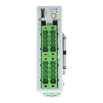
1. PARTS DESCRIPTION
Module mainframe
Terminal type (4-channel type)
Connector type (4-channel type)
Indication
Loader
Loader
lamps
communication
communication
connector
Address
connector
setting
CT Input
CT Input
switch
connector
connector
(Optional)
(Optional)
CH3
CH1
CH3
CH1
Input/Output
Input/Output
terminals
connector
The 2-channel type (Z-TIO-B)
CH4
CH2
does not have CH 3 and CH 4
CH4
CH2
Input/Output terminals or
Input/Output connectors.
For the appearance of Z-TIO-B,
refer to SRZ Instruction
Manual (IMS01T04-E).
[These diagrams represent any module of SRZ.]
[Indication lamps]
FAIL/RUN
When normal (RUN):
A green lamp is on
Self-diagnostic error (FAIL):
A green lamp flashes
Instrument abnormality (FAIL): A red lamp is on
RX/TX
During data send and receive: A green lamp turns on
Base
Joint connector
Mounting holes (M3 screw)
Used to mechanically and
Holes for screws to fix the base
electrically connect each module.
to a panel, etc.
Customer must provide the M3
Power supply terminals
screws.
Supply power to only one of the joined
modules, and all of the joined modules
will receive power.
(Refer to 3.1 Wiring Cautions.)
1 2
Mounting bracket
Communication terminals
Used to fix the module on DIN
(RS-485)
3 4 5
rails and also to fix each module
Connect communication wires to only
joined together.
one of the joined modules, and all of
the joined modules will communicate.
2. MOUNTING
WARNING
!
To prevent electric shock or instrument failure, always turn off the
power before mounting or removing the instrument.
2.1 Mounting Cautions
(1) This instrument is intended to be used under the following environmental conditions.
(IEC 61010-1) [OVERVOLTAGE CATEGORY II, POLLUTION DEGREE 2]
(2) Use this instrument within the following environment conditions:
Allowable ambient temperature:
10 to 50 C
Allowable ambient humidity:
5 to 95 %RH
(Absolute humidity: MAX. W. C 29.3 g/m
3
dry air at 101.3 kPa)
Installation environment conditions: Indoor use
Altitude up to 2000 m
(3) Avoid the following conditions when selecting the mounting location:
Rapid changes in ambient temperature which may cause condensation.
Corrosive or inflammable gases.
Direct vibration or shock to the mainframe.
Water, oil, chemicals, vapor or steam splashes.
Excessive dust, salt or iron particles.
Excessive induction noise, static electricity, magnetic fields or noise.
Direct air flow from an air conditioner.
Exposure to direct sunlight.
Excessive heat accumulation.
(4) Mount this instrument in the panel considering the following conditions:
Ensure at least 50 mm space on top and bottom of the instrument for maintenance and
environmental reasons.
Do not mount this instrument directly above the equipment that generates large amount of
heat (heaters, transformers, semi-conductor functional devices, large-wattage resistors).
If the ambient temperature rises above 50 C, cool this instrument with a forced air fan,
cooler, etc. Cooled air should not blow directly on this instrument.
In order to improve safety and the immunity to withstand noise, mount this instrument as
far away as possible from high voltage equipment, power lines, and rotating machinery.
High voltage equipment: Do not mount within the same panel.
Power lines:
Separate at least 200 mm.
Rotating machinery:
Separate as far as possible.
(5) If this instrument is permanently connected to equipment, it is important to include a
switch or circuit-breaker into the installation. This should be in close proximity to the
equipment and within easy reach of the operator. It should be marked as the
disconnecting device for the equipment.
2.2 Dimensions
Indication
[Terminal type]
[Connector type]
lamps
85
76.9
Address
setting
switch
Space required between each module
Depth for connector mount type module
Space for connectors and cables must be
vertically
considered when installing.
When the module is mounted on the panel,
allow a minimum of 50 mm at the top and
bottom of the module to attach the module
to the mainframe.
76.9
50 mm or more
2.3 DIN Rail Mounting
Mounting procedures
1.
Pull down the mounting bracket at the bottom of the module (A). Attach the hooks on the
top of the module to the DIN rail and push the lower section into place on the DIN rail (B).
2.
Slide the mounting bracket up to secure the module to the DIN rail.
DIN rail
Mounting
(B) Push
bracket
(A) Pull down
Mounting end plates
To firmly fix the modules, use end plates on both sides of the mounted modules.
Z-TIO modules
End Plate
(sold separately)
[Code: DEP-01]
Joint connector cover
*
[Code: KSRZ-517A]
* It is recommended to use a plastic cover on the connector on both sides of the mounted
modules for protection of connectors.
Removal procedures
Pull down a mounting bracket with
a blade screwdriver (A). Lift the
module from bottom, and take it
off (B).
(Unit: mm)
2.9
30
6.7
2.4 Panel Mounting
Mounting procedures
1. Refer to the mounting dimensions below when selecting the location.
(30)
300.2
Approx.
(Unit: mm)
Mounting dimensions
50
2. Remove the base from the module (B) while the lock is pressed (A). (Fig.1)
Connector
.
3. Join bases
Then, lock them by pushing in the mounting brackets.
(plug)
Refer to the 2.5 Joining Each Module.
4. Fix the base to its mounting position using M3 screws. Customer must provide the
screws.
5. Mount the module on the base. (Fig.2)
Lock
(B)
(A)
(Bottom of the module mainframe)
Fig. 1: Removing the base
2.5 Joining Each Module
Up to 16 Z-TIO-A/B modules (for host communication) can be joined together. Join these
modules according to the following procedure.
Z-TIO-C or Z-TIO-D module for which the communication protocol is "PLC
(C) Locked
communication" cannot be connected to and used with a Z-TIO-A or Z-TIO-B
module.
1. Mount the modules on the DIN rail.
2. Slide the modules until the modules are closely joined together and the joint connectors
are securely connected.
End Plate
3. Push in the mounting brackets to lock the modules together and fix to the DIN rail.
(sold separately)
[Code: DEP-01]
For panel mounting, mount the module mainframes after the bases are joined
and mounted.
(Front view of module mainframe)
Joint connector
(B)
Lift and
take off
(A) Pull down
(Unit: mm)
M3
Recommended screw:
M3 10
Recommended
tightening torque:
0.3 N・m (3 kgf・cm)
Base
(Top of the module mainframe)
(Base)
Fig. 2: Mounting the module mainframe
(Rear view of base)
State where
each module is
locked.
Mounting
bracket
Push in all of
the mounting brackets.
Advertisement

Related Manuals for RKC INSTRUMENT SRZ Z-TIO-A


Summary of Contents for RKC INSTRUMENT SRZ Z-TIO-A
- Page 1 RKC. (5) If this instrument is permanently connected to equipment, it is important to include a All Rights Reserved, Copyright 2006, RKC INSTRUMENT INC. off (B). IMS01T01-E7 switch or circuit-breaker into the installation. This should be in close proximity to the 1.
- Page 2 Class II (Reinforced insulation) Current input input W-BW-03- ( : Standard cable length [unit: mm]) Cable type: EMC: EN61326-1 RKC INSTRUMENT INC. 1000: 1m, 2000: 2 m, 3000: 3 m The first edition: MAR. 2006 [IMQ00] ...
Need help?
Do you have a question about the SRZ Z-TIO-A and is the answer not in the manual?
Questions and answers