RKC INSTRUMENT RB100 Communication Quick Manual
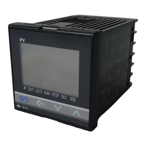
Digital temperature controller
Hide thumbs
Also See for RB100:
- Instruction manual (306 pages) ,
- Installaiton instructions (2 pages) ,
- Manual (9 pages)
Table of Contents
Advertisement
Quick Links
Download this manual
See also:
Instruction Manual
Digital Temperature Controller
Communication
RB100/RB400/RB900
Quick Manual
All Rights Reserved, Copyright 2008, RKC INSTRUMENT INC.
Thank you for purchasing this RKC product. In order to achieve maximum performance
and ensure proper operation of your new instrument, carefully read all the instructions in
this manual. Please place this manual in a convenient location for easy reference.
This manual describes the connection method with host computer, communication
parameters and communication data (except for parameters in engineering mode) of the
RB100/RB400/RB900.
For detailed host communication such as protocol description, see the Communication
Instruction Manual (IMR02C16-E ).
The Communication Instruction Manual can be downloaded from our website:
URL: http://www.rkcinst.com/english/manual_load.htm
1. CONNECTION TO HOST COMPUTER
!
WARNING
To prevent electric shock or instrument failure, turn off the power before
connecting or disconnecting the instrument and peripheral equipment.
Make sure that lugs or unshielded cables of the communication terminals are
not touched to the screw heads, lugs, or unshielded cables of the power
supply terminals to prevent electric shock or instrument failure. Use additional
care when two lugs are screwed to one communication terminal.
The cable must be provided by the customer.
1.1 Communication terminal number and signal details
Terminal No.
Signal name
Symbol
13
Signal ground
SG
14
Send/Receive data
T/R (A)
15
Send/Receive data
T/R (B)
1.2 Wiring method
When the interface of host computer (Master) is RS-485
Paired wire
Controller (Slave)
RS-485
Host computer (Master)
SG
13
SG
(−)
T/R (A) 14
T/R (A)
T/R (B)
15
T/R (B)
(+)
*R
Shielded twisted
pair wire
Screw size: M3×7 (with 5.8×5.8 square washer)
Controller (Slave)
Recommended tightening torque:
SG
0.4 N・m (4 kgf・cm)
13
Recommended solderless terminals:
(−)
T/R (A) 14
Manufactured by J.S.T MFG CO., LTD.
Circular terminal with isolation V1.25-MS3
(M3 screw, width 5.5 mm, hole diameter 3.2 mm)
T/R (B)
15
(+)
*R
*R: Termination resistors (Example: 120 Ω 1/2 W)
Maximum connections: Up to 31 instruments
When the host computer (Master) has a USB connector
Connect the USB communication converter between the host computer and the controller.
Host computer (Master)
Connect to
USB port
USB cable
Paired wire
(COM-K accessory)
RS-485
Controller (Slave)
SG
13
1
SG
(−)
T/R (A) 14
2
T/R (A)
T/R (B)
3
T/R (B)
15
(+)
4
Unused
Shielded twisted
5
Unused
pair wire
USB communication converter
COM-K (RKC product)
Controller (Slave)
Screw size: M3×7 (with 5.8×5.8 square washer)
SG
13
Recommended tightening torque:
(−)
0.4 N・m (4 kgf・cm)
T/R (A) 14
Recommended solderless terminals:
Manufactured by J.S.T MFG CO., LTD.
T/R (B)
15
(+)
Circular terminal with isolation V1.25-MS3
*R
(M3 screw, width 5.5 mm, hole diameter 3.2 mm)
*R: Termination resistors (Example: 120 Ω 1/2 W)
Maximum connections: Up to 31 instruments
For the COM-K, see the COM-K Instruction Manual (IMR01Z01-E ).
2. SETTING
To establish communication parameters between host computer and controller, it is
necessary to set the following parameters.
When all communication parameter settings have been completed, turn the power
IMR02C14-E1
off and then on to make the new set values take effect.
This instrument returns to the PV/SV monitor screen if no key operation is
performed for more than one minute
This section describes the parameters which must be set for communication. For
the mode/parameters transfer and data setting, see the RB100/RB400/RB900
Quick
Operation
Manual
(IMR02C12-E )
Parameter List (IMR02C13-E ).
Description of each parameters (Engineering mode F60)
Symbol
Name
Data range
Function block
This is the first parameter symbol of function block 60.
60
(F60.)
Communication
0: RKC communication
Use to select a protocol of
protocol
1: Modbus
communication function.
(CMPS)
Device address
0 to 99
Do not use the same device
(Slave address)
address for more than one
(Modbus: 1 to 99)
instrument in multi-drop
(Add)
connection.
Communication
0: 2400 bps
Set the same communication
speed
1: 4800 bps
speed for both the controller
2: 9600 bps
(slave) and the host
(bPS)
3: 19200 bps
computer (master).
Data bit
See Data bit
Set the same data bit
configuration
configuration table
configuration for both the
controller (slave) and the host
(bIT)
computer (master).
Interval time
0 to 250 ms
The interval time for the
controller should be set to
provide a time for host
computer to finish sending all
data including stop bit and to
switch the line to receive
(INT)
status for the host.
Data bit configuration:
Set
Data
Parity
Stop
Settable
Set
value
bit
bit
bit
communication
value
0
8
Wi t hout
1
6
1
8
Wi t hout
2
7
RKC
(−)
2
8
Even
1
communication
8
3
8
Even
2
9
Modbus
(+)
4
8
Odd
1
10
5
8
Odd
2
11
Interval time:
The interval time for the controller should be set to provide a time for host computer to
finish sending all data including stop bit and to switch the line to receive status for the host.
If the interval time between the two is too short, the controller may send data before the
host computer is ready to receive it. In this case, communication transmission cannot be
conducted correctly.
3. COMMUNICATION REQUIREMENTS
Processing times during data send/receive
When the host computer is using either the polling or selecting procedure for
communication, the following processing times are required for controller to send data:
- Response wait time after controller sends BCC in polling procedure
- Response wait time after controller sends ACK or NAK in selecting procedure
Response send time is time when interval time is set at 0 ms.
RKC communication (Polling procedure)
Procedure details
Response send time after controller receives ENQ
Response send time after controller receives ACK
Connect to
Response send time after controller receives NAK
USB connector
of COM-K
Response send time after controller sends BCC
The termination
RKC communication (Selecting procedure)
resistor is built
into the COM-K.
Procedure details
Response send time after controller receives BCC
Response wait time after controller sends ACK
Response wait time after controller sends NAK
Modbus
Procedure details
Read holding registers [03H]
Response send time after the slave receives the query message
Preset single register [06H]
Response send time after the slave receives the query message
Diagnostics (loopback test) [08H]
Response send time after the slave receives the query message
RS-485 send/receive timing (RKC communication)
RS-485 communication is conducted through two wires, therefore the transmission and
reception of data requires precise timing.
Polling procedure
Possible
Send data
Host
(Possible/Impossible)
Impossible
computer
Sending status
Possible
Send data
(Possible/Impossible)
Impossible
Controller
Sending status
and
RB100/RB400/RB900
: Response send time after the controller receives [ENQ] + Interval time
a
b: Response send time after the controller sends BCC
c: Response send time after the controller receives [ACK] + Interval time or
Response send time after the controller receives [NAK] + Interval tim
Factory
Selecting procedure
Description
set value
Possible
Send data
Host
(Possible/Impossible)
Impossible
computer
Sending status
Depends
Send data
Possible
on model
(Possible/Impossible)
Impossible
code
Controller
0
Sending status
(Modbus: 1)
a: Response send time after the controller receives BCC + Interval time
b: Response wait time after the controller sends ACK or Response wait time after the controller sends NAK
3
To switch the host computer from transmission to reception, send data must be on
line.
The following processing times are required for the controller to process data.
0
- In Polling procedure, Response wait time after the controller sends BCC
- In Selecting procedure, Response wait time after the controller sends ACK or
NAK
10
Fail-safe
A transmission error may occur with the transmission line disconnected, shorted or set to
the high-impedance state. In order to prevent the above error, it is recommended that the
fail-safe function be provided on the receiver side of the host computer. The fail-safe
function can prevent a framing error from its occurrence by making the receiver output
stable to the MARK (1) when the transmission line is in the high-impedance state.
Data backup
Data
Parity
Stop
Settable
The nonvolatile memory (EEPROM) for data backup has limitations on the number of
bit
bit
bit
communication
memory rewrite times (approx. 1,000,000 times). If set values are frequently changed
7
Wi t hout
1
through communication, please select "Buffer mode" in the EEPROM mode (Identifier:
7
Wi t hout
2
EB).
7
Even
1
RKC
communication
7
Even
2
Modbus data processing precautions
7
Odd
1
7
Odd
2
• The numeric range of data used in Modbus protocol is 0000H to FFFFH. Only the set
value within the setting range is effective.
FFFFH represents −1.
• Data with decimal point is treated as data without decimal point on the Modbus protocol.
• If data (holding register) exceeding the accessible address range is accessed, an error
response message is returned.
• Read data of unused item is a default value.
• Any attempt to write to an unused item is not processed as an error. Data cannot be
written into an unused item.
• If data range or address error occurs during data writing (Write Action), it is not
processed as an error. Normal data is written in data register but data with error is not
written; therefore, it is recommended to confirm data of changed items after the data
setting.
• An attribute of the item for functions which are not in the controller is RO (read only). If
read action to this item is performed, the read data will be "0." If write action to this item
is performed, no error message is indicated and no data is written.
• Commands should be sent at time intervals of 24 bits after the master receives the
response message.
Time
4. COMMUNICATION DATA LIST
60 ms max.
60 ms max.
The communication data map shows data which can be used for communication between
60 ms max.
the host computer and controller.
52 ms max.
Explanation of data map items
• Modbus register address
Time
HEX: Hexadecimal
65 ms max.
• Attribute (A method of how communication data items are read or written when
52 ms max.
viewed from the host computer is described)
52 ms max.
RO: Read only data
R/W: Read and Write data (Host computer ↔ Controller)
• Data
Time
RKC communication
60 ms max.
ASCII code data of 6 digits
65 ms max.
..........
Most significant
60 ms max.
digit
Communication data (RKC communication)
During polling/selecting mode, data transmission can be continuously made by ACK in the
following ranges:
• From "Measured value (PV) monitor" to "Manipulated output ON/OFF state monitor
[cool-side]"
• From "Model code" to "Integrated operating time monitor"
E
E
A
N
O
- - - - -
N
C
or
A
Name
K
K
T
Q
a
b
c
Measured value (PV)
monitor
S
B
T
- - - - -
C
X
C
Current transformer 1
(CT1) input value
monitor
Current transformer 2
e
(CT2) input value
monitor
Event 1 state monitor
Event 2 state monitor
S
B
T
- - - - -
C
X
C
Burnout state monitor
a
b
Error code
A
N
or
C
A
K
K
RUN/STOP transfer
Set value 1 (SV1)
Event 1 set value
(EV1)
Event 1 set value
(EV1) [high]
Event 2 set value
(EV2)
Event 2 set value
(EV2) [high]
Heater break alarm 1
(HBA1) set value
Heater break alarm 2
(HBA2) set value
Control loop break
alarm (LBA) time
LBA deadband (LBD)
Autotuning (AT)
Unused
Proportional band
[heat-side]
Integral time [heat-side]
Derivative time [heat-side]
Anti-reset windup
(ARW)
Proportional cycle
time [heat-side]
Proportional band
[cool-side]
Overlap/Deadband
Proportional cycle
time [cool-side]
PV bias
Set lock level
DEC: Decimal
EEPROM mode
(Host computer ← Controller)
EEPROM state
Modbus
16-bit data
Interlock release
Event 1 delay timer
..................................
Least significant
Bit 15
Bit 0
Event 2 delay timer
digit
RKC
Attri-
Factory
Iden-
Data range
bute
set value
tifier
M1
RO
Within input range
For input range, see "4. MODEL CODE" of
RB100/RB400/RB900 Installation Manual (IMR02C11-E ).
M2
RO
0.0 to 100.0 A
M3
RO
AA
RO
0: Event 1 OFF
1: Event 1 ON
AB
RO
0: Event 2 OFF
1: Event 2 ON
B1
RO
0: OFF
1: ON (burnout)
ER
RO
1: Adjustment data error
2: Data back-up error
4: A/D conversion error (Including temperature
compensation error)
SR
R/W
0: RUN
0
1: STOP
S1
R/W
Setting limiter (low) to Setting limiter (high)
0
Deviation action: −Input span to +Input span
A1
R/W
TC/RTD:
50 (50.0)
Input value or set value action:
Same as input range
V/I: 5.0
− Input span to + Input span
(When event code U, X, Y or Z is selected.)
A2
R/W
The data range is the same as "Event 1 set value
TC/RTD:
(EV1)."
50 (50.0)
V/I: 5.0
The data range is the same as "Event 1 set value
(EV1) [high]."
A3
R/W
0.0 to 100.0 A
0.0
A4
R/W
0.0
A5
R/W
0 to 7200 seconds (0: Unused)
480
A6
R/W
0 to Input span
0
G1
R/W
0: PID control
0
1: AT start
G2
R/W
Must be always "0"
P1
R/W
TC/RTD inputs:
TC/RTD:
1 (0.1) to Input span (Unit: °C [°F])
30 (30.0)
Voltage (V)/current (I) inputs:
V/I: 3.0
0.1 to 100.0 % of Input span
0 (0.0): ON/OFF action
I1
R/W
1 to 3600 seconds (0: PD action)
240
D1
R/W
1 to 3600 seconds (0: PI action)
60
W1
R/W
1 to 100 % of proportional band [heat-side]
100
(0: Integral action is always OFF)
T0
R/W
0 to 100 seconds
M: 20
V, T, D: 2
(0: Setting below 1 second is possible for "Proportional
cycle time [heat-side]" in the engineering mode)
M: Relay contact output
V: Voltage pulse output
T: Triac output
D: Open collector output
P2
R/W
1 to 1000 % of proportional band [heat-side]
100
(ON/OFF control of cool-side only is not possible)
V1
R/W
TC/RTD inputs:
0 (0.0)
−10 (−10.0) to +10 (+10.0) °C [°F]
Voltage (V)/current (I) inputs:
−10.0 to +10.0 % of Input span
T1
R/W
0 to 100 seconds
M: 20
V, T, D: 2
(0: Setting below 1 second is possible for "Proportional
cycle time [cool-side]" in the engineering mode)
PB
R/W
TC/RTD inputs:
0 (0.0)
−1999 (−199.9) to +9999 (+999.9) °C [°F]
Voltage (V)/current (I) inputs:
− Input span to + Input span
LK
R/W
0 to 10
0
For details of set lock level, see "■Engineering Mode" of
RB100/RB400/RB900 Parameter List (IMR02C13-E ).
The set data lock function is effective only for the setting
performed by key operation. Locked items by set data lock
function can be changed via communication.
EB
R/W
0: Backup mode
0
(Set values are store to the EEPROM when
set values are changed.)
1: Buffer mode
(Not set values are store to the EEPROM
when set values are changed.)
EM
RO
0: The content of the EEPROM does not coincide
with that of the RAM.
1: The content of the EEPROM coincides with
that of the RAM.
IR
R/W
To release the interlock, write "0 (zero)."
0
TD
R/W
0 to 600 seconds
0
TG
R/W
0
Data can be written only in STOP mode.
Continued on the next page
Advertisement
Table of Contents

Related Manuals for RKC INSTRUMENT RB100


Summary of Contents for RKC INSTRUMENT RB100
- Page 1 (except for parameters in engineering mode) of the Controller For input range, see “4. MODEL CODE” of the mode/parameters transfer and data setting, see the RB100/RB400/RB900 RB100/RB400/RB900 Installation Manual (IMR02C11-E ). RB100/RB400/RB900. Sending status - - - - -...
- Page 2 0 (0.0) trademarks of the respective companies. heat/cool control type. (LBA) time limiter (low) LBA deadband (LBD) Data 0: Display RKC INSTRUMENT INC. F03 block selection 0: Display ® The first edition: APR. 2008 [IMQ00] (no display) 1: No display...
Need help?
Do you have a question about the RB100 and is the answer not in the manual?
Questions and answers