Table of Contents
Advertisement
Quick Links
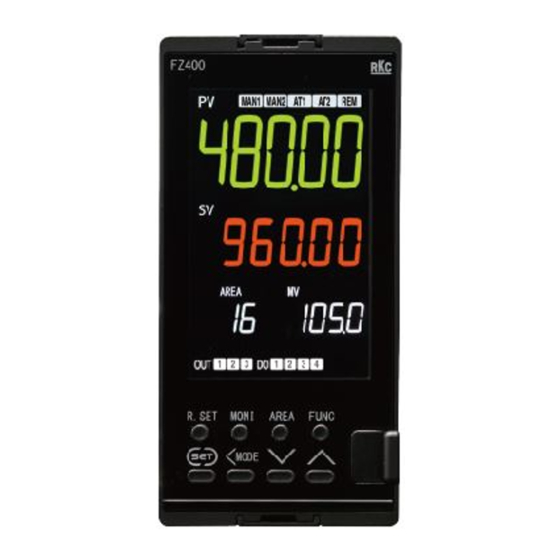
Temperature Controller
Quick Operation
FZ110/FZ400/FZ900
Manual
IMR03A02-E2
All Rights Reserved, Copyright 2016, RKC INSTRUMENT INC.
Thank you for purchasing this RKC product. In order to achieve maximum performance and ensure
proper operation of the instrument, carefully read all the instructions in this manual. Please place
the manual in a convenient location for easy reference. This manual descries basic key operations
of the FZ110/400/900.
For detailed handling procedures and key operations, refer to separate
FZ110/FZ400/FZ900 Instruction Manual.
The manual can be downloaded from the official RKC website:
http://www.rkcinst.com/english/manual_load.htm
Notes for the display
FZ110/400/900 are available in two types: single input type and dual input type.
The dual input type is further categorized into two types: Dual PV type (for FZ400/900) and
PV + Remote setting type (for FZ110/400/900).
For a dual input model, the same parameter may exist in both Input 1 and Input 2.
"1." or "2." is added to the top of the parameters for identification.
Input 1_Set value (SV)
Input 2_Set value (SV)
1.
8
8SV
2.
8
8SV
Display example
of the dual input
0
0
type
"1." is not added to the top of the parameters list for the single input type.
Set value (SV)
Display example
1. 8
8SV
of a single input
type
0
This manual uses the dual inputs for explanation. For other types such as a single input
type, ignore the first character "1." at the top of the parameter.
Parameters used only for the second input are shown in the colored background.
[Notation in this manual]
2. SV
This part is not
Parameter shown
1.
8
8SV
displayed on
only on the dual
the single input
0
input type
type.
2. CHANGING SET VALUE
The flashing digit indicates which digit can be set. Press
MODE
key to go to a different digit. Every time the
shift key is pressed, the flashing digit moves as follows.
All modes except SV setting mode
A: SV setting mode
and Parameter setting mode
F: Parameter setting mode
AREA
SV
SV
8 8 8 8 8
8 8 8 8
8
Flashing
The following is also available when changing the set value.
8
210
8
210
Increase SV from
Once
199 to 200
00199
00200
Flashing
8
210
8
210
MODE
Decrease SV from
Once
200 to 190
0200
00200
Flashing
8
210
8
210
MODE
Decrease SV from
200 to 100
Twice
00200
00200
Flashing
To store a new value for the parameter, always press the
key. The display changes to the next parameter
and the new value will be stored. The modified data will not be stored only by operating the
keys. In the Operation transfer mode, however, the selected mode will be valid only by the operations of these
keys.
In case of the Set value (SV), the instrument can be configured in the H: Engineering mode so that the
modified set value will be adopted 2 seconds after the change without pressing the
In case no operation is performed within 60 seconds after the change of the setting, the mode will return to
A: Monitor and SV setting mode. The modified data will not be registered in this case.
5. SET THE EVEVT SET VALUE
As shown below, the Event trigger values are set according to the preset event types.
Set the Event 1 set value (EV1) to 100 C
A: Monitor & SV setting mode
Input 1_
8
210
Measured
value (PV)/
0
Set value
(SV) monitor
(2 seconds)
F: Parameter setting mode
Pn00
Parameter
group No. 00:
SV
Setting
Parameter
Pn40
group No. 40:
EV
Event
2EV1
2EV2
Event 1 set
Event 2 set
value (EV1)
value (EV2)
00050
00050
Flashing
MODE
(Once)
2EV1
2EV1
(5 times)
00100
00050
Flashing
8. MEMORY AREA TRANSFER
The memory area to be used for control (control area) can be switched to the desired area.
Change control area from No. 1 to No. 2
FZ400/900
FZ110
A: Monitor & SV setting mode
A: Monitor & SV setting mode
Control area No. 1
Control area No. 1
Input 1_
8
210
8
210
Measured
Measured
value (PV)/
AREA
AREA
value (PV)/
1
0
1
Set value
Set value
(SV) monitor
(SV) monitor
AREA
(Once or Twice)
E: Memory area transfer mode
AREA
AREA
Memory area
Memory area
AREA
AREA
transfer
transfer
1
00001
1
00001
Flashing
AREA
AREA
AREA
AREA
00002
00002
1
1
Control area No. 2
Control area No. 2
Input 1_
8
210
Measured
8
210
Measured
value (PV)/
value (PV)/
AREA
AREA
2
100
Set value
2
100
Set value
(SV) monitor
(SV) monitor
1. SWITCHING BETWEEN MODES
Power ON
Model, Input type
and Input range
FZ900
Model
FZ110, FZ400 or FZ900
@C88K
(Example: FZ900)
Automatically (in 1 second)
Input symbol
1.
8
INP
Unit for input 1
Temperature input: C or F
@C88K
Voltage/Current input:
No display
Input type for input 1
(Refer to the Input type
symbol table)
Automatically (in 1 second) *
1372
Input 1_Input range high
-200
Input 1_Input range low
Automatically (in 1 second) *
Unit for input 2 and
2. INP
Input type for input 2
@C K
(Refer to Input 1 for the displayed
contents.)
Automatically (in 1 second)
1372
Input 2_Input range high
and Input 2_Input range low
-200
* Displayed for 2 seconds
Automatically
(Single input type)
(in 1 second)
0
3. SET THE SET VALUE (SV)
Set value (SV) is the control target value.
Set the Input 1_Set value (SV) to 200 C
[Auto mode (RUN)]
A: Monitor & SV setting mode
8
Input 1_
8
PV1
Measured
Flashing
value (PV)/
Set value (SV)
monitor
PV1
8
Input 1_
Set value (SV)
00000
setting
8
210
8
PV1
Once
00190
00000
Flashing
Flashing
8
210
8
PV1
3 times
-0100
00200
Flashing
and
D1 O
PV2
Input 2_
Set value (SV)
00000
setting
key.
To return to the top of the list, press the MONI key or the
Press the
6. RUN/STOP TRANSFER
The control is switched between RUN and STOP. The instrument must be
stopped before attempting the setting in the Engineering mode.
Change form RUN to STOP
[Auto mode (RUN)]
A: Monitor & SV setting mode
Input 1_
8
210
Measured
0
value (PV)/
Set value
(SV) monitor
MODE
(2 seconds)
C: Operation transfer mode
82R/S
RUN/STOP
transfer
RUN
RUN state
(2 seconds)
or
Change form STOP to RUN
+
MODE
[Auto mode (STOP)]
A: Monitor & SV setting mode
Input 1_
8
210
Measured
STOP
value (PV)/
Set value
(SV) monitor
MODE
(2 seconds)
C: Operation transfer mode
82R/S
RUN/STOP
transfer
STOP
STOP state
Outline of memory area
The Memory area function is to store up to 16 areas (patterns) of parameters such as
a Set value (SV). This parameter can be found in the F: Parameter setting mode. Any
one area out of 16 areas can be called up for the control.
Parameter groups in F: Parameter setting mode
No. 00:
No. 40 *:
Setting
Event
0
No. 70:
No. 56 *:
Memory area
Input 1_
function
Cool control
* Parameter group Nos. 40, 52, and 56 may not be displayed depending on the
specification.
One memory area consists of six parameter groups.
To change a memory area number to another, when a certain parameter is
MODE
displayed, press the
key to shift the flashing digit to the left until the
Flashing
flashing digit reaches the AREA digit.
[Example: Memory area transfer of set value (SV)]
Memory area No. 1
Pn00
1. P0SV
(5 times)
AREA
AREA
1
SV
1
00100
Flashing
Memory area No. 2
For the Memory area transfer, the
values of the parameters will change
AREA
when the Memory area No. is
2
switched. No storing operation by the
key is required.
Flashing
X Y: Press X and Y keys simultaneously
Legend X: Press X key once
X (n times):
Press X key n times
X (n seconds):
Press and hold X key for n seconds or more.
X Y (n seconds): Press and hold X and Y keys simultaneously for n seconds
B
Parameter select
mode
F
Parameter setting
(2 seconds)
mode
G
Setup setting
mode
Input type symbol
K J T S r E B n P
Symbol
TC
Input type
K
J
T
S
R
E
B
N
W
U L PR PT JP
V
Symbol
TC
RTD
Input type
Voltage Current
W5Re/
PR40
U
L
Pt100 JPt100
W26Re
-20
[Auto mode (STOP)]
[Manual mode]
A: Monitor & SV setting mode
A: Monitor & SV setting mode
210
Input 1_
8
210
Input 1_
PV1
Measured
Measured value
0
value (PV)/
STOP
(PV)/Manipulated
Set value (SV)
output value (MV)
monitor
monitor
(MAN1 lamp ON)
210
Input 1_
Set value (SV)
setting
Flashing
(Twice)
MODE
210
(Twice)
210
A single input type and FZ110 have different screens.
100
Input 2_
Flashing
Set value (SV)
setting
key until the first parameter is displayed (for FZ400/900).
key until the first parameter is displayed (for FZ110).
7. AUTO/MANUAL TRANSFER
The control mode is switched between AUTO and MANUAL.
Switching Input 1 to Manual mode
[Auto mode (RUN)]
[Auto mode (STOP)]
A: Monitor & SV setting mode
A: Monitor & SV setting mode
Input 1_
8
Input 1_
8
210
Measured
Measured
value (PV)/
STOP
value (PV)/
Set value
Set value
(SV) monitor
(SV) monitor
MODE
(2 seconds)
C: Operation transfer mode
or
82R/S
+
MODE
RUN/STOP
transfer
82R/S
SToP
STOP state
1.
Input 1_
Auto/Manual
transfer
[Auto mode (RUN)]
A: Monitor & SV setting mode
Input 1_
8
210
While the Input 1_PV/SV monitor is displayed on FZ400/900, the Input
Measured
1_Manipulated output value (MV) can be displayed on the MV display
0
value (PV)/
unit (third display unit). Similarly, while the Input 2_ PV/SV monitor is
Set value
displayed on FZ400/900, the Input 2_Manipulated output value (MV)
(SV) monitor
MODE
can be displayed on the MV display unit (third display unit).
These parameters are set in H: Engineering mode.
(2 seconds)
or
Measured value (PV) display
+
MODE
Set value (SV) display
82R/S
Manipulated output value (MV) display
rUn
RUN state
9. SWITCHING TO THE ON/OFF ACTION
To switch to the ON/OFF action, set the Proportional band to zero (0).
Control the Input 1 with the ON/OFF action
A: Monitor & SV setting mode
No. 51:
Input 1_
8
210
Input 1_
Measured
Control
value (PV)/
0
Set value
(SV) monitor
(2 seconds)
No. 52 *:
Input 2_
F: Parameter setting mode
Control
Pn00
Parameter
group No. 00:
SV
Setting
(Once or Twice)
Pn51
Parameter
group No. 51:
1. C onT
Input 1_
Control
MODE
1. P0SV
Input 1_
AREA
1. 21SP
1
00100
Proportioning
band
00030
Flashing
[heat-side]
(Once)
MODE
1. P0SV
1. 21SP
00200
00030
Flashing
Display of
each mode
・MONI
Automatically
・SET+<MODE
When the Blind
・No key is operated
Auto-
function is activated.
for 60 seconds.
matically
MODE
+
Any one of the above
A
Monitor & SV setting
mode
+
MODE
+
MODE
(2 seconds)
H
+
MODE
Engineering mode
(2 seconds)
PL II
Parameters in the Engineering mode should be set according to the application before setting any
I
parameters related to operation. Once the Parameters in the Engineering mode are set correctly, no
further changes need to be made to parameters for the same application under normal conditions. If they
are changed unnecessarily, it may result in malfunction or failure of the instrument. RKC will not bear any
responsibility for malfunction or failure as a result of improper changes in the Engineering mode.
4. SET AUTOTUNING (AT)
The Autotuning (AT) function automatically measures, computes and sets the optimum PID values.
Set the Input 1_Autotuning (AT)
A: Monitor & SV setting mode
PV1
Input 1_
8
210
PV1
Measured value (PV)/
Set value (SV) monitor
105. 0
C: Operation transfer mode
1. 21SV
Flashing
RUN/STOP transfer
00000
(Twice)
MODE
1. 21SV
Input 1_
Autotuning (AT)
00000
(Twice)
Flashing
1. 21SV
00200
2. SV
Flashing
00000
Manipulated output value setting
in manual mode
After the Manual mode is selected using the Auto/Manual transfer, set the
Manipulated output value (MV) on the PV/MV monitor in the A: Monitor & SV
setting mode using the
[Manual mode]
[Manual mode]
A: Monitor & SV setting mode
A: Monitor & SV setting mode
210
Input 1_
8
210
Measured
Input 1_Measured
0
value (PV)/
105. 0
value (PV)/Manipulated
Set value
output value (MV)
monitor
MODE
(SV) monitor
(2 seconds)
Press the
MODE
(2 seconds)
Press the
or
If the
RUN
+
MODE
Manipulated output value (MV) will be accelerated.
The output value adjusted with the
(Several times)
immediately.
2
A/M
1.
2
A/M
AUTO
MAN
Auto mode
Manual mode
(MAN1 lamp ON)
88888
88888
88888
10. SET DATA UNLOCK/LOCK TRANSFER
This is a function to lock the set data to restrict the change of the set data.
Locking the Engineering mode
A: Monitor & SV setting mode
Input 1_
(2 seconds)
Measured
value (PV)/
or
Set value
+
MODE
(SV) monitor
Input 1_
1. 2PRT
Control
D: Setting lock mode
response
00000
parameter
Set data
Set the ON/OFF action
unlock/lock
differential gap (lower)
transfer
followed by pressing the
key.
Input 1_
1. 2oHL
ON/OFF
action
00001
differential
gap lower
Set the ON/OFF action
differential gap (upper)
followed by pressing the
key.
Input 1_
1. 2oHH
ON/OFF
Set lock
Flashing
action
level
00001
differential
gap upper
Change to
the ON/OFF
0: Unlock
action
1: Lock
1. 21SP
(3 times)
"0" setting
00000
The Set lock level can be changed even after the set data lock has been set.
E
AREA
Memory area
transfer mode
(Only FZ400/900 *)
* For FZ110, the Memory area
transfer can be found in the
Monitor and SV setting mode.
C
MODE
Operation transfer
(2 seconds)
mode
D
(4 seconds)
Setting lock mode
+
MODE
(2 seconds)
8
210
0
MODE
(2 seconds)
82R/S
RUN
MODE
or
1.
8
ATU
oFF
1.
8
ATU
AT1 lamp flashing
on
[AT start]
MODE
(2 seconds)
or
+
MODE
and
keys.
8
210
PV1
(MAN1 lamp ON)
105. 0
key to increase the Manipulated output value (MV).
key to decrease the Manipulated output value (MV).
or
key is kept pressing, the changing rate of the
and
keys will be valid
* When the
key is pressed and held for a
certain period of time, the Parameter setting
8
210
mode will be displayed once. If the SET key is
kept pressing without releasing the finger from
0
the key, the Setting lock mode is entered.
(4 seconds)
(4 seconds*)
or
+
MODE
LOCK
ARE. LK
Unlock
Area lock
state
oFF
00000
Flashing
LOCK
LCK. LV
Engineering
Set lock
mode is
on
10000
locked
LCK. LV
MODE
(4 times)
LCK. LV
00000
00000
Flashing
Flashing
A: SV setting mode **
C: Operation transfer mode
F: Parameter setting mode
** Including "B: Parameter
G: Setup setting mode
select mode"
H: Engineering mode
Advertisement
Table of Contents

Related Manuals for RKC INSTRUMENT FZ110


Summary of Contents for RKC INSTRUMENT FZ110
- Page 1 Temperature input: C or F @C88K MODE Monitor & SV setting Operation transfer Voltage/Current input: FZ110/400/900 are available in two types: single input type and dual input type. No display (2 seconds) Parameter setting (2 seconds) Input type for input 1...
- Page 2 11. CHANGE OF THE INPUT TYPE The Input related parameters may include: Input type, Display unit, Decimal point position, Input range high, and Input range low. These parameters can be set in the H: Engineering mode. Changing the Input 1 to Thermocouple type J (0 to 800°C) [Data range of decimal point position] A: Monitor &...
Need help?
Do you have a question about the FZ110 and is the answer not in the manual?
Questions and answers