RKC INSTRUMENT RB100 Instruction Manual
Rb series digital temperature controller
Hide thumbs
Also See for RB100:
- Communication quick manual (2 pages) ,
- Installaiton instructions (2 pages) ,
- Manual (9 pages)

Related Manuals for RKC INSTRUMENT RB100


Summary of Contents for RKC INSTRUMENT RB100
- Page 1 RB SERIES Digital Temperature Controller RB100/RB400 RB500/RB700 RB900 Instruction Manual IMR02C15-E4 RKC INSTRUMENT INC. ®...
- Page 2 Modbus is a registered trademark of Schneider Electric. Company names and product names used in this manual are the trademarks or registered trademarks of the respective companies. All Rights Reserved, Copyright 2009, RKC INSTRUMENT INC.
- Page 3 Thank you for purchasing this RKC product. In order to achieve maximum performance and ensure proper operation of your new instrument, carefully read all the instructions in this manual. Please place the manual in a convenient location for easy reference. NOTICE This manual assumes that the reader has a fundamental knowledge of the principles of electricity, process control, computer technology and communications.
- Page 4 CAUTION This product is intended for use with industrial machines, test and measuring equipment. (It is not designed for use with medical equipment and nuclear energy.) This is a Class A instrument. In a domestic environment, this instrument may cause radio interference, in which case the user may be required to take additional measures.
-
Page 5: Safety Symbols
SYMBOLS Safety Symbols: : This mark indicates precautions that must be taken if there is danger of electric WARNING shock, fire, etc., which could result in loss of life or injury. : This mark indicates that if these precautions and operating procedures are not CAUTION taken, damage to the instrument may result. - Page 6 Unit character symbols °C °F Abbreviation symbols These abbreviations are used in this manual: Abbreviation Name symbols Measured value (PV) Set value (SV) Autotuning Startup tuning HBA1 Heater break alarm 1 HBA2 Heater break alarm 2 Current transformer 1 Current transformer 2 Control loop break alarm LBA deadband Event set value...
- Page 7 Communication Quick IMR02C41-E This manual is enclosed with instrument. RB series Instruction Manual (Only RB100/RB400/RB500/RB700/RB900s provided with the communication function) (RB100/400/500/700/900) This manual explains the connection method with host computer, communication parameters, and communication data (except for parameters in Engineering Mode).
-
Page 8: Table Of Contents
Quick start code (Initial setting code) ..............1-7 1.5 Parts Description ..................1-8 1.6 Handling Procedure to Operation ...............1-13 2. MOUNTING ................2-1 2.1 Mounting Cautions..................2-2 2.2 Dimensions....................2-3 RB100 ........................2-3 RB400 ........................2-3 RB500 ........................2-4 RB700 ........................2-4 RB900 ........................2-5 2.3 Procedures of Mounting and Removing ............2-6 The mounting position of mounting bracket............2-6... - Page 9 Page Digital input (DI1, DI2) [optional]................3-13 Current transformer (CT) input [optional]..............3-13 Communication [optional] ..................3-14 3.4 Handling of the Terminal Cover [optional] ..........3-15 Mounting procedures....................3-15 Removal procedures ....................3-16 4. BASIC OPERATION ............4-1 4.1 Operation Menu....................4-2 4.2 Changing Set Value..................4-4 5. SETUP PROCEDURES PRIOR TO RUNNING THE INSTRUMENT............5-1 5.1 Initial Setting ....................5-3 Check the parameter related to the input ...............5-3...
- Page 10 Page 6.3 Startup Tuning (ST) ..................6-11 Caution for using the Startup tuning (ST) .............6-11 Requirements for Startup tuning (ST) start............6-12 Requirements for Startup tuning (ST) cancellation..........6-12 Startup tuning (ST) setting..................6-13 6.4 Fine Tuning....................6-17 To make control response faster ................6-17 To make control response slower.................6-18 6.5 Auto/Manual Transfer .................6-20 Bumpless function with Auto/Manual transfer ............6-20 Auto/Manual transfer by front key operation............6-21...
- Page 11 Page 7.3 Transmission Output Function..............7-12 Setting procedure ....................7-12 Output calibration ....................7-13 8. PARAMETER DESCRIPTION ...........8-1 8.1 Monitor Display Mode ...................8-2 8.1.1 Display sequence....................8-2 8.1.2 Monitor item ......................8-3 8.2 SV Setting Mode...................8-6 8.2.1 Display sequence....................8-6 8.2.2 Setting item .......................8-7 8.3 Mode Switching ....................8-9 8.3.1 Display sequence....................8-9 8.3.2 Operation item....................8-10 8.4 Parameter Setting Mode................8-12...
- Page 12 Page 9. TROUBLESHOOTING ............9-1 9.1 Error Display....................9-2 Display when input error occurs ................9-2 Self-diagnostic error ....................9-3 9.2 Solutions for Problems .................9-4 Display........................9-5 Control ........................9-6 Operation........................9-8 Event function......................9-9 Heater break alarm (HBA) ..................9-9 10. SPECIFICATIONS ............10-1 APPENDIX ................A-1 A. Removing the Internal Assembly..............A-2 B.
-
Page 13: Outline
OUTLINE This chapter describes features, package contents and model code, etc. 1.1 Features ...................1-2 1.2 Input/Output and Function Blocks.............1-3 1.3 Checking the Product ...............1-4 1.4 Model Code ..................1-5 Suffix code ....................1-5 Quick start code (Initial setting code)............1-7 1.5 Parts Description ................1-8 1.6 Handling Procedure to Operation ...........1-13 IMR02C15-E4... -
Page 14: Features
1. OUTLINE 1.1 Features This high performance digital controller has the following features: Panel space saving: 60 mm depth (RB400/500/700/900), 63 mm (RB100) 11-segment LCD display for the PV display Sampling time 250 ms Advanced autotuning with ARW function “Fine tuning” that changes responsiveness A new 6 level Fine tuning allows the operator to control response from fast to slow by changing the Fine tuning setting (−3 to... -
Page 15: Input/Output And Function Blocks
• Manipulated output RUN/STOP transfer value (MV1) (Front key, DI, communication) OUT2 can be used as Event 3 output for RB100. Delay timer Event 1 to 4 processing Digital input • Temperature alarm • Dry contact • Heater break alarm... -
Page 16: Checking The Product
Q’TY Remarks Instrument RB900 Waterproof/Dustproof type: 4 Mounting bracket (with screw) Case rubber packing Waterproof/Dustproof type KRB100-39 (RB100) KFB400-36<1> (RB400/500) KRB700-310 (RB700) KFB900-36<1> (RB900) Installation Manual (IMR02C38-E ) Enclosed with instrument Quick Operation Manual (IMR02C39-E ) Enclosed with instrument... -
Page 17: Model Code
Transmission output can be specified as output 2 (OUT2), when Control Method is “F” (reverse action) or “D” (direct action). For RB100, Output 2 (OUT2) can be specified as event output 3, when Control Method is “F”(reverse action) or “D” (direct action) and two digital outputs (DO1 and DO2) are specified. - Page 18 Output type Remarks Relay contact output [Cool output] Relay contact output [Event 3 output] Only RB100 (PID control) Voltage pulse output [Cool output] Voltage output (0 to 5 V DC) Current output (0 to 20 mA DC)
-
Page 19: Quick Start Code (Initial Setting Code)
AUTO/MAN transfer + Interlock release For Heat/Cool control type, the LBA function cannot be specified. In case of RB100, this code is selectable when “P” is specified for “(4) output 2 (OUT2).” In case of RB100, this code must be “N: None.”... -
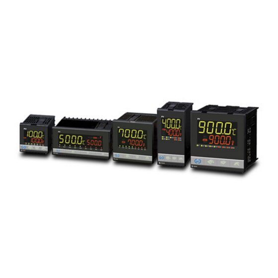
Page 20: Parts Description
1. OUTLINE 1.5 Parts Description This section describes various display units and the key functions. Front Panel View RB100 ‡‡‡‡ Unit display [Green] Measured value (PV) display [Green] ‰ Set value (SV) display [Orange] 8888 STEP set value lamp [Orange]... - Page 21 1. OUTLINE RB500 STEP set value lamp [Orange] ‡‡‡‡ Set lock display [Orange] SV1 SV2 SV3 SV4 Measured value (PV) 8888 display [Green] Set value (SV) display ‰ [Orange] Unit display [Green] Autotuning (AT) lamp [Green] OUT1 OUT2 STOP Output (OUT) lamp [Green] Manual (MAN) mode lamp [Green] RB500 STOP lamp [Green]...
-
Page 22: Display Units
Blinks when control is stopped (STOP) by the Timer function (P. 7-5). Digital output (DO) lamp [Green] Lights when the Event (RB100: DO1, DO2 RB400/500/700/900: DO1 to DO4) output corresponding to each lamp is ON. STEP set value lamp [Orange] When the Step SV function (P. - Page 23 1. OUTLINE Bottom View RB100 RB400 RB900 Loader communication connector (Standard equipment) RB500 * RB700 * Side view Loader communication connector (Standard equipment) Loader communication Setting and monitoring on a personal computer (PC) is possible if the controller is connector...
- Page 24 How to connect the controller to a PC via loader communication port Connect the controller, COM-K, and personal computer using a USB cable and a loader communication cable. Make sure the connectors are oriented correctly when connecting. (RB100) USB cable 1 m Connect to loader...
-
Page 25: Handling Procedure To Operation
1. OUTLINE 1.6 Handling Procedure to Operation After installation and wiring, follow the procedure below to configure settings required for operation. Power ON Conditions specified at time of ordering are acceptable Set operation conditions? You wish to change conditions Change from RUN to STOP Press the key for more than 2 seconds to change the RUN/STOP (Factory set value: RUN) - Page 26 MEMO 1-14 IMR02C15-E4...
-
Page 27: Mounting
MOUNTING This chapter describes installation environment, mounting cautions, dimensions and mounting procedures. 2.1 Mounting Cautions................2-2 2.2 Dimensions ..................2-3 RB100......................2-3 RB400......................2-3 RB500......................2-4 RB700......................2-4 RB900......................2-5 2.3 Procedures of Mounting and Removing..........2-6 The mounting position of mounting bracket..........2-6 Mounting procedures (Not supplied) ............2-7 Mounting procedures (Waterproof/Dustproof type) ........2-8... -
Page 28: Mounting Cautions
2. MOUNTING 2.1 Mounting Cautions WARNING To prevent electric shock or instrument failure, always turn off the power before mounting or removing the instrument. (1) This instrument is intended to be used under the following environmental conditions. (IEC61010-1) [OVERVOLTAGE CATEGORY II, POLLUTION DEGREE 2] (2) Use this instrument within the following environment conditions: •... -
Page 29: Dimensions
2. MOUNTING 2.2 Dimensions Panel thickness: 1 to 10 mm (When mounting multiple RB series controllers close together, the panel strength should be checked to ensure proper support.) RB100 Individual mounting +0.6 (Unit: mm) Close horizontal mounting +0.6 79.1 L1 = 48 × n − 3... -
Page 30: Rb500
2. MOUNTING Panel thickness: 1 to 10 mm (When mounting multiple RB series controllers close together, the panel strength should be checked to ensure proper support.) RB500 Individual mounting (Unit: mm) +0.8 Close horizontal mounting +0.8 70.1 L1 = 48×n − 3 n = Number of controllers (2 to 6) RB700... -
Page 31: Rb900
2. MOUNTING Panel thickness: 1 to 10 mm (When mounting multiple RB series controllers close together, the panel strength should be checked to ensure proper support.) RB900 Individual mounting (Unit: mm) +0.8 Close horizontal mounting +0.8 70.1 L1 = 96×n − 4 n = Number of controllers (2 to 6) *1 Case rubber packing (optional) [Waterproof/Dustproof] *2 Terminal cover (optional) [sold separately]... -
Page 32: Procedures Of Mounting And Removing
2. MOUNTING 2.3 Procedures of Mounting and Removing The mounting position of the mounting bracket (1) Mounting positions for single controller RB100 RB400 RB500 RB700 RB900 * If two mounting brackets are used on the Waterproof/Dustproof type controller as shown in the figure (marked*), sufficient Waterproof/Dustproof performance cannot be obtained. -
Page 33: Mounting Procedures (Not Supplied)
2. MOUNTING Mounting procedures (Not supplied) Prepare the panel cutout as specified in 2.2 Dimensions. Fig. 2.1 Panel (Panel thickness: 1 to 10 mm) Mounting holes Fig. 2.2 Insert the instrument through the panel cutout. (Fig. 2.2) Panel Fig. 2.3 Insert the mounting bracket into the mounting groove of the instrument. -
Page 34: Mounting Procedures (Waterproof/Dustproof Type)
2. MOUNTING Mounting procedures (Waterproof/Dustproof type) The front of the instrument conforms to IP66 (NEMA4X) [Specify when ordering] when mounted on the panel. For effective Waterproof/Dustproof, the gasket must be securely placed between instrument and panel without any gap. If gasket is damaged, please contact RKC sales office or the agent. 1. -
Page 35: Removal Procedures
2. MOUNTING Removal procedures Turn the power OFF. Fig. 2.11 Remove the wiring. Loosen the screw of the mounting bracket. (Fig. 2.11) Lift the latch of the mounting bracket ( ), then pull the mounting bracket ( ), to remove it from the case. Loosen the screw (Fig. - Page 36 MEMO 2-10 IMR02C15-E4...
-
Page 37: Wiring
WIRING This chapter describes wiring cautions, wiring layout and wiring of terminals. 3.1 Wiring Cautions ................3-2 3.2 Terminal Layout ................3-5 3.3 Wiring of Each Terminal ..............3-8 3.4 Handling of the Terminal Cover [optional]........3-15 IMR02C15-E4... -
Page 38: Wiring Cautions
3. WIRING 3.1 Wiring Cautions WARNING To prevent electric shock or instrument failure, do not turn on the power until all wiring is completed. Make sure that the wiring is correct before applying power to the instrument. • For thermocouple input, use the appropriate compensation wire. •... - Page 39 • When wiring of RB100/400/700/900, wire from the left direction toward the backside terminals as shown in Fig. 3.2. For RB100, the wiring surfaces of the central and right side lines of terminals are inclined to make it easier to wire from the left side.
- Page 40 3. WIRING • Caution for the terminal cover usage: − To prevent electric shock or instrument failure, always turn off the power before mounting or removing the terminal cover. − When mounting and removing the terminal cover, apply pressure very carefully to avoid damage to the terminal cover.
-
Page 41: Terminal Layout
3. WIRING 3.2 Terminal Layout The terminal layout is as follows. RB100 Communication and Digital input (DI1, DI2) • Communication * [Refer to P. 3-14] RS-485 • Digital input 2 (DI2) Digital input 1 (DI1) * [Refer to P. 3-13]... -
Page 42: Rb500
3. WIRING RB500 Digital input 2 (DI2), Digital output 4 (DO4), Digital input 1 (DI1) * Digital output 3 (DO3) * [Refer to P. 3-13] [Refer to P. 3-11] Dry contact input Relay contact (2) Current transformer (CT) Communication * input 2 (CT2), [Refer to P. -
Page 43: Rb900
3. WIRING RB900 Power supply voltage [Refer to P. 3-8] 100 to 240 V AC, 24 V AC, 24 V DC Communication * Output 2 (OUT2) [Refer to P. 3-14] [Refer to P. 3-9] RS-485 Relay contact (1)/Voltage pulse/ Voltage/Current/Triac/ Digital input 2 (DI2), Open collector Digital input 1 (DI1) *... -
Page 44: Wiring Of Each Terminal
Power supply type Power consumption code 90 to 264 V AC (Power supply voltage range), RB100: 5.5 VA max. (at 100 V AC), [Rating 100 to 240 V AC] 8.5 VA max. (at 240 V AC) Power supply frequency: 50/60 Hz RB400/500/700: 6.0 VA max. -
Page 45: Output 1 (Out1)/Output 2 (Out2)
− Heat/Cool PID control: − Heat/Cool PID control: OUT2 corresponds to the cool-side output OUT1 can be used only as the heat-side output − Specify when Event 3 output (Only RB100) * * Specify when ordering Continued on the next page. IMR02C15-E4... -
Page 46: Transmission Output (Ao) [Optional]
Electrical life: 100,000 times or more (Rated load) * For RB100, Output 2 (OUT2) can be specified as event output 3, when Control Method is “F”(reverse action) or “D” (direct action) and two digital outputs (DO1 and DO2) are specified. -
Page 47: Digital Output 1 To 4 (Do1 To Do4) [Optional]
• Outputs of DO1/DO2 and DO3/DO4 are isolated. DO1 and DO2 or DO3 and DO4 use the same common terminal (RB100/400/500/900: No. 9 for DO1/DO2, and No. 21 for DO3/DO4 RB700: No. 12 for DO1/DO2, and No. 9 for DO3/DO4) and are not isolated. -
Page 48: Measured Input (Thermocouple/Rtd/Voltage/Current) [Universal Input]
3. WIRING Measured input (Thermocouple/RTD/Voltage/Current) [universal input] • For the measured input type, terminals 10 through 12 (RB700: terminals 16 through 18) are allocated to the measured input. RB100/400/500/900: RTD input Voltage input Current input * Thermocouple input − −... -
Page 49: Digital Input (Di1, Di2) [Optional]
3. WIRING Digital input (DI1, DI2) [optional] • Models that were specified with digital input when ordering can use the following terminal numbers. RB100: Terminal No. 13 to 15 (DI1, DI2) RB700: Terminal No. 22 to 24 (DI1, DI2) RB400/500/900: Terminal No. 16 to 18 (DI1, DI2) -
Page 50: Communication [Optional]
• With Communication function, terminals 13 through 15 (RB700: terminals 25 through 27) are allocated to Communication. RS-485 RS-485 T/R (A) T/R (A) T/R (B) T/R (B) RB700 RB100/400/500/900 For the wiring, refer to Communication Quick Instruction Manual (IMR02C41-E ) or Communication Instruction Manual (IMR02C16-E ). 3-14 IMR02C15-E4... -
Page 51: Handling Of The Terminal Cover [Optional]
Remove and use it depending on the wiring condition. Drawing of RB900 with terminal cover RB900 is used in the explanatory drawing. The above mounting procedures in the example shown are the same for RB100, RB400, RB500 and RB700. 3-15 IMR02C15-E4... -
Page 52: Removal Procedures
3. WIRING Drawing of RB400 with terminal cover Drawing of RB100 with terminal cover This section of RB400/500/900 terminal cover can be removed by bending it. Remove and use it depending on the wiring condition. Removal procedures Release the protrusions of terminal cover from the insertion slots ( ) shown in the following figure, and then pull the terminal cover ( ) to remove it from the case. -
Page 53: Basic Operation
BASIC OPERATION This chapter explains the basic operations of switching modes and changing set values. 4.1 Operation Menu ................4-2 4.2 Changing Set Value ................4-4 IMR02C15-E4... -
Page 54: Operation Menu
4. BASIC OPERATION 4.1 Operation Menu The controller has five different modes. All settable parameters belong to one of them. The following chart show how to access different setting mode. For the details of changing set value, refer to 4.2 Changing Set Value (P. 4-4). Power ON Input type/Input range Display SV Setting Mode... - Page 55 4. BASIC OPERATION Monitor Display Mode (2 seconds or more) [Figures on the SV display shows a “factory set value.”] Parameter Setting Mode F01 to F10 indicate group numbers used in Non-display of block and Set lock level in Engineering mode. Parameters in F01 to F03 as well as F10 are not displayed with the factory default setting.
-
Page 56: Changing Set Value
4. BASIC OPERATION 4.2 Changing Set Value • The flashing digit indicates which digit can be set. Press key to go to a different digit. Every time the shift key is pressed, the flashing digit moves as follows. Flashing • The following is also available when changing the set value. Increase SV from 199 °C to 200 °C: 1. - Page 57 SETUP PROCEDURES PRIOR TO RUNNING THE INSTRUMENT This chapter explains basic setup procedures prior to running the instrument. 5.1 Initial Setting...................5-3 Check the parameter related to the input ..........5-3 Check the parameter related to the event ..........5-4 Check the parameter related to the control action........5-5 5.2 Operation Setting ................5-6 Set the control set value ................5-6 Set the event set value ................5-7...
-
Page 58: Setup Procedures Prior To Running The Instrument
5. SETUP PROCEDURES PRIOR TO RUNNING THE INSTRUMENT Setup the controller prior to operating the instrument. Refer to the following setup example. Setup example Input specification: Thermocouple (K) 0 to 400 °C Control action: PID action with AT (Reverse action) Event specification (Event 1): Deviation high/low with hold action (Uses Interlock function) 200 °C... -
Page 59: Initial Setting
5. SETUP PROCEDURES PRIOR TO RUNNING THE INSTRUMENT 5.1 Initial Setting Check the parameter related to the input Parameter settings related to the control input specifications such as the input type, can be checked in Engineering mode. Parameters which are not specified when ordering must be set before use. Setup example: (K) 0 to 400 °C [Input range code: K02] Input specification: Thermocouple... -
Page 60: Check The Parameter Related To The Event
5. SETUP PROCEDURES PRIOR TO RUNNING THE INSTRUMENT Check the parameter related to the event Parameter settings related to event action can be checked in Engineering mode. Parameters which are not specified when ordering must be set before use. Setup example: Event specification (Event 1): Deviation high/low with hold action [Quick start code: G]... -
Page 61: Check The Parameter Related To The Control Action
5. SETUP PROCEDURES PRIOR TO RUNNING THE INSTRUMENT Check the parameter related to the control action Parameter settings related to control action can be checked in Engineering mode. Parameters which are not specified when ordering must be set before use. Setup example: PID action with AT (Reverse action) Control action:... -
Page 62: Operation Setting
5. SETUP PROCEDURES PRIOR TO RUNNING THE INSTRUMENT 5.2 Operation Setting Set the control set value After finishing the initial settings, set the control target value, SV. [Setting example: Set the control set value 1 (SV1) to 200 °C.] 1. Make sure that the PV/SV monitor screen is displayed, and SV1 is selected (factory set value: SV1), then press the key to go to the SV setting mode. -
Page 63: Set The Event Set Value
5. SETUP PROCEDURES PRIOR TO RUNNING THE INSTRUMENT Set the event set value After finishing the initial settings, set the event set values if they are used. [Setting example: Set the Event 1 set value (EV1) to 20 °C] 1. Press and hold the key for 2 seconds or more at the PV/SV monitor screen until the Parameter setting mode screen is displayed. -
Page 64: Operation Start
A power failure of 20 ms* or less will not affect the control action. When a power failure of more than 20 ms* occurs the instrument assumes that the power has been turned off. * 10ms for RB100 with 24V AC/DC power supply Action at power fail recovery The instrument will return to the same RUN/STOP state and the same operation mode which were used by the instrument before power failure. -
Page 65: Change From Stop To Run
5. SETUP PROCEDURES PRIOR TO RUNNING THE INSTRUMENT Change from STOP to RUN To start control, change the RUN/STOP mode from STOP (stop control) to RUN (start control). Press and hold the key for 2 seconds or more at the PV/SV monitor screen and the instrument will switch from STOP to RUN. -
Page 66: Tuning Pid Parameters
5. SETUP PROCEDURES PRIOR TO RUNNING THE INSTRUMENT Tuning PID parameters Suitable PID values are automatically calculated by Autotuning (AT) function. The Autotuning (AT) function automatically measures, computes and sets the optimum PID values. Before start autotuning, make sure that all required conditions (refer to P. 6-8) to start AT are satisfied. -
Page 67: To Manually Adjust The Pid Parameters
5. SETUP PROCEDURES PRIOR TO RUNNING THE INSTRUMENT To manually adjust the PID parameters If the Autotuning (AT) function does not match the controlled object requirements, the optimum PID values may not be calculated by Autotuning (AT). In that case, adjust the PID parameters manually. •... -
Page 68: Changing Control Response With Fine Tuning
5. SETUP PROCEDURES PRIOR TO RUNNING THE INSTRUMENT Changing control response with Fine tuning After suitable PID values are calculated and stored by Autotuning or manual PID setting, the Fine tuning allows you to change the control response of the same PID constant control. The control response can be changed from fast to slow by simply changing the Fine tuning setting (6 levels: −3 to +3) in Parameter setting mode while the PID constant is unchanged. -
Page 69: Operations Of The Basic Functions
OPERATIONS OF THE BASIC FUNCTIONS This chapter describes the basic functions and the procedures for using basic functions. 6.1 RUN/STOP Transfer................6-2 6.2 Autotuning (AT) ................6-8 6.3 Startup Tuning (ST) ...............6-11 6.4 Fine Tuning..................6-17 6.5 Auto/Manual Transfer ..............6-20 6.6 Protecting Setting Data (Data lock function) ........6-24 6.7 Display/No display Setting of Mode Screens .........6-32 6.8 Interlock Release ................6-39 IMR02C15-E4... -
Page 70: Run/Stop Transfer
6. OPERATIONS OF THE BASIC FUNCTIONS 6.1 RUN/STOP Transfer It is possible to transfer between control start (RUN) and control stop (STOP). RUN/STOP transfer can be performed by key operation, by key operation using the RUN/STOP setting in Engineering mode, by digital input (DI) [optional] or communication [optional]. All methods of RUN/STOP operation are linked. -
Page 71: Run/Stop Transfer By Front Key Operation
6. OPERATIONS OF THE BASIC FUNCTIONS RUN/STOP transfer by front key operation Press and hold the key for 2 seconds or more at the PV/SV monitor screen and the instrument will switch from STOP to RUN. PV/SV monitor (STOP mode) PV/SV monitor (RUN mode) STOP Set value (SV) display... - Page 72 6. OPERATIONS OF THE BASIC FUNCTIONS 3. Press the key to change the number to 1 (1: STOP). Press the key to store the new value. RUN/STOP setting (Engineering mode) F00. 0000 0001 OUT1 OUT2 OUT1 OUT2 OUT1 OUT2 STOP STOP STOP STOP lamp lights...
-
Page 73: Run/Stop Transfer By Digital Input (Di) [Optional]
6. OPERATIONS OF THE BASIC FUNCTIONS 3. Press the key to change the number to 0 (0:RUN). Press the key to store the new value. RUN/STOP setting (Engineering mode) F00. 0001 0000 OUT1 OUT2 OUT1 OUT2 OUT1 OUT2 STOP STOP STOP STOP lamp turns off Setting range:... -
Page 74: Terminal Configuration
COM (−) COM (−) COM (−) Contact closed: RUN Contact open: STOP RB100 RB400/500/900 RB700 When the initial set code of DI assignment is “5: RUN/STOP transfer + AUTO/MAN transfer,” “6: RUN/STOP transfer + Interlock release” Dry contact input... - Page 75 6. OPERATIONS OF THE BASIC FUNCTIONS RUN/STOP transfer state The table below shows the actual RUN/STOP modes, displays, and STOP lamp states under different combinations of settings by key operation, communication, digital input (DI), and STOP by the timer function. RUN/STOP mode STOP by Actual...
-
Page 76: Autotuning (At)
When the Autotuning (AT) does not end in 9 hours after Autotuning (AT) started. When the power failure of more than 20 ms occurs. Power failure (10 ms or more for RB100 with 24V AC/DC power supply.) Instrument error When the instrument is in the FAIL state. -
Page 77: Autotuning (At) Start/Stop Operation
6. OPERATIONS OF THE BASIC FUNCTIONS Autotuning (AT) start/stop operation The Autotuning function can start from any state after power on, during a rise in temperature or in stable control. Start AT 1. Press and hold the key for 2 seconds or more at the PV/SV monitor screen to go to the Parameter setting mode, and press the key to display the Autotuning (AT) screen. - Page 78 6. OPERATIONS OF THE BASIC FUNCTIONS Autotuning (AT) cancellation When canceling the Autotuning function (AT), press the key to be set to “0000” with the Autotuning (AT) screen. Parameter setting mode Autotuning (AT) 0001 0000 Autotuning (AT) cancellation (0: PID control) OUT1 OUT2 OUT1...
-
Page 79: Startup Tuning (St)
6. OPERATIONS OF THE BASIC FUNCTIONS 6.3 Startup Tuning (ST) Startup tuning (ST) is a function which automatically computes and sets the PID values (Proportional band: heat-side only) from the response characteristics of the controlled system at power ON, transfer from STOP to RUN, and Set value (SV) change. -
Page 80: Requirements For Startup Tuning (St) Start
When the Startup tuning (ST) does not end in hundred minutes after Startup tuning (ST) started Power failure When the power failure of more than 20 ms occurs. (10 ms or more for RB100 with 24V AC/DC power supply.) Instrument error When the instrument is in the FAIL state. 6-12... -
Page 81: Startup Tuning (St) Setting
6. OPERATIONS OF THE BASIC FUNCTIONS Startup tuning (ST) setting The setting procedure when executing Startup tuning (ST) only one time at power ON is shown below as a setting example. Set the ST start condition First, set “When the power is turn on” to ST start condition by Engineering mode. 1. - Page 82 6. OPERATIONS OF THE BASIC FUNCTIONS Set “128” (128: Display F21 and following) in the Mode selection (no display) screen and then press the key to store the set value. Press the key several times until the Function block 00 screen is displayed. Function block 00 Mode selection (no display) RUN/STOP setting...
- Page 83 6. OPERATIONS OF THE BASIC FUNCTIONS 7. Press the key several times until Function block 00 screen is displayed. 8. Press the key several times until Mode selection (no display) screen is displayed. Change the value in the Mode selection (no display) screen to the original value and then press key to store the set value.
- Page 84 6. OPERATIONS OF THE BASIC FUNCTIONS 4. In the Startup tuning (ST) screen, press the key to set the value of the flashing digit to “1” (1: Execute once). Press the key to store the new value. Displays the next parameter Proportional band [heat-side] Startup tuning (ST) 0000...
-
Page 85: Fine Tuning
6. OPERATIONS OF THE BASIC FUNCTIONS 6.4 Fine Tuning The Fine tuning function allows you to change the response of the set PID constant control. Control by PID constant control. Overshoot Faster response Set value (SV) Higher Lower setting setting Slower response Difference in control response due to fine tuning To make control response faster... - Page 86 6. OPERATIONS OF THE BASIC FUNCTIONS Continued from the previous page. 4. Press the key to store the new value. The display goes to the next parameter. Fine tuning begins when the key is pressed. Displays the next parameter. The displayed parameter varies depending on the 0003...
- Page 87 6. OPERATIONS OF THE BASIC FUNCTIONS 4. Press the key to store the new value. The display goes to the next parameter. Fine tuning begins when the key is pressed. Displays the next parameter. The displayed parameter varies depending on the -003 0020 product specifications.
-
Page 88: Auto/Manual Transfer
6. OPERATIONS OF THE BASIC FUNCTIONS 6.5 Auto/Manual Transfer The Auto/Manual transfer can be made by digital input (DI) * or communication * other than the key operation. * Optional For details of Auto/Manual transfer by communication, refer to the Communication Instruction Manual (IMR02C16-E ). -
Page 89: Auto/Manual Transfer By Front Key Operation
6. OPERATIONS OF THE BASIC FUNCTIONS Auto/Manual transfer by front key operation This is performed in Auto/Manual transfer of Mode switching. Auto/Manual transfer can be done in the Mode switching. Every time the key or the key is pressed, the Auto (AUTO) mode is changed to the Manual (MAN) mode alternately. -
Page 90: Auto/Manual Transfer By Digital Input (Di)
Auto/Manual transfer by the digital input (DI) is possible with the DI assignment of the Engineering mode. For the DI assignment, refer to 8.5 Engineering Mode (P. 8-95). Terminal configuration Digital input (DI1, DI2) RB100 RB400/500/900 RB700 DI1 or DI2: Auto/Manual transfer input Contact closed: Auto (AUTO) mode... -
Page 91: Procedure For Setting The Manipulated Output Value (Mv) In Manual Mode
6. OPERATIONS OF THE BASIC FUNCTIONS Procedure for setting the Manipulated output value (MV) in Manual mode When the controller is in Manual mode, the Manipulated output value (MV) can be manually set. Make sure the Manual (MAN) mode lamp is lit. PV/SV monitor OUT1 OUT2... -
Page 92: Protecting Setting Data (Data Lock Function)
6. OPERATIONS OF THE BASIC FUNCTIONS 6.6 Protecting Setting Data (Data lock function) To protect setting data in the instrument, the setting data can be locked so that no changes can be made (Data lock function). Parameters that can be locked are described below. •... -
Page 93: Set Lock Level Of Parameter Setting Mode
6. OPERATIONS OF THE BASIC FUNCTIONS Set lock level of Parameter setting mode The same parameters exist in Engineering mode, grouped by group number (F01 to F10) as shown below. In the Set lock level (LocK) screen, you can lock the group number that contains the parameter(s) that you wish to lock, and this will lock the same parameters in Parameter setting mode. -
Page 94: Locking All Data Which Can Be Locked
6. OPERATIONS OF THE BASIC FUNCTIONS Locking all data which can be locked Parameters that can be locked: − Parameters of Parameter setting mode − Parameters of F01 to F91 of Engineering mode 1. In PV/SV monitor, press the key for 4 seconds or more while pressing the key. - Page 95 6. OPERATIONS OF THE BASIC FUNCTIONS 5. Press the key while pressing the key. The display goes to the Engineering mode. PV/SV monitor MoNI 0000 OUT1 OUT2 OUT1 OUT2 + STOP STOP 6. In PV/SV monitor, press the key while pressing the key.
-
Page 96: Selecting The Parameter To Lock
6. OPERATIONS OF THE BASIC FUNCTIONS Selecting the parameter to lock Setting example: Locking the Proportional band [heat-side] and following parameters in Parameter setting mode To lock Proportional band [heat-side] and following parameters, choose a suitable Set lock level by which Function block F06 is locked. - Page 97 6. OPERATIONS OF THE BASIC FUNCTIONS 5. Press the key while pressing the key. The display goes to the PV/SV monitor. PV/SV monitor MoNI 0000 OUT1 OUT2 OUT1 OUT2 + STOP STOP 6. In PV/SV monitor, press the key while pressing the key.
-
Page 98: Locking F21 To F91 Data
6. OPERATIONS OF THE BASIC FUNCTIONS Locking F21 to F91 data To lock F21 to F91, set any value from “1” to “10” in the Set lock level, and enable the Data lock function in the Set data unlock/lock screen. When locked, the screens of F21 to F91 will not be displayed even if “128”... - Page 99 6. OPERATIONS OF THE BASIC FUNCTIONS 5. Press the key while pressing the key. The display goes to the PV/SV monitor. PV/SV monitor MoNI 0000 OUT1 OUT2 OUT1 OUT2 + STOP STOP 6. In PV/SV monitor, press the key while pressing the key.
-
Page 100: Display/No Display Setting Of Mode Screens
6. OPERATIONS OF THE BASIC FUNCTIONS 6.7 Display/No display Setting of Mode Screens The instrument can be set not to display parameters that are not used (note that some parameters cannot be set to “no display”). Parameters that can be set to “no display” are shown below. Monitor display mode: Engineering mode (F00): PV/SV monitor... - Page 101 6. OPERATIONS OF THE BASIC FUNCTIONS Engineering mode: Function block 00 (F00) Cannot be set to no display. Function block 01 (F01) Function block 03 (F03) Function block 04 (F04) Function block 06 (F06) Function block 07 (F07) Function block 08 (F08) Function block 09 (F09) Function block 10 (F10) Function block 21 (F21)
-
Page 102: Hiding The Parameters Of The Monitor Display Mode
6. OPERATIONS OF THE BASIC FUNCTIONS Hiding the parameters of the Monitor display mode Setting example: The Current transformer 1 (CT1) input value monitor and Current transformer 2 (CT2) input value monitor are set to no display. 1. In PV/SV monitor, press the key for 4 seconds or more while pressing the key. -
Page 103: Hiding The Parameters Of The Mode Switching Screen
6. OPERATIONS OF THE BASIC FUNCTIONS Hiding the parameters of the Mode switching screen Setting example: Set data unlock/lock transfer is set to no display. 1. In PV/SV monitor, press the key for 4 seconds or more while pressing the key. - Page 104 6. OPERATIONS OF THE BASIC FUNCTIONS Screen displays of Function block 21 (F21) to Function block 91 (F91) WARNING Parameters in the Engineering mode (F21 to F70) should be set according to the application before setting any parameter related to operation. Once the parameters in the Engineering mode are set correctly, no further changes need to be made to parameters for the same application under normal conditions.
-
Page 105: Hiding The Parameters Of The Parameter Setting Mode
6. OPERATIONS OF THE BASIC FUNCTIONS Hiding the parameters of the Parameter setting mode Setting example: Setting the PV bias screen and PV digital filter screen to no display The PV bias and PV digital filter screens are set by the F09 block selection (no display) of Engineering mode. -
Page 106: Displaying Function Block 21 (F21) To Function Block 91 (F91) Of The Engineering Mode
6. OPERATIONS OF THE BASIC FUNCTIONS Displaying Function block 21 (F21) to Function block 91 (F91) of the Engineering mode WARNING Parameters in the Engineering mode (F21 to F70) should be set according to the application before setting any parameter related to operation. Once the parameters in the Engineering mode are set correctly, no further changes need to be made to parameters for the same application under normal conditions. -
Page 107: Interlock Release
6. OPERATIONS OF THE BASIC FUNCTIONS 6.8 Interlock Release The interlock action holds the event state even if the measured value is out of the event zone after it enters the event zone once. The interlock release can be made by digital input (DI) [optional], or communication [optional] other than the key operation. -
Page 108: Interlock Release By Front Key Operation
6. OPERATIONS OF THE BASIC FUNCTIONS Interlock release by front key operation 1. In PV/SV monitor, press the key while pressing the key. Mode switching Auto (AUTO)/Manual (MAN) transfer PV/SV monitor AUTO 0000 OUT1 OUT2 OUT1 OUT2 + STOP STOP 2. -
Page 109: Interlock Release By Digital Input (Di)
Interlock release by the digital input (DI) is possible with the DI assignment of the Engineering mode. For the DI assignment, refer to 8.5 Engineering Mode (P. 8-95). Terminal configuration Digital input (DI1, DI2) RB100 RB400/500/900 RB700 DI2: Interlock release input... - Page 110 MEMO 6-42 IMR02C15-E4...
-
Page 111: Operating Additional Functions
OPERATING ADDITIONAL FUNCTIONS This chapter describes the setting procedure for additional functions. 7.1 SV Selection Function (Step SV function) ........7-2 Setting procedure ..................7-2 SV selection by front key operation ...............7-3 SV selection by digital input (DI)..............7-4 7.2 Timer Function ................7-5 Control start (RUN) by Timer function (Timer function 1).......7-5 Control stop (STOP) by Timer function (Timer function 2)......7-7 Ramp/Soak control (Timer function 3, Timer function 4)........7-9... -
Page 112: Sv Selection Function (Step Sv Function)
7. OPERATING ADDITIONAL FUNCTIONS 7.1 SV Selection Function (Step SV function) The SV selection function enables control by switching to any one of the stored set values of up to four points (SV1 to SV4). The Set value (SV) selecting can be made by digital input (DI) [optional] or communication [optional] other than the key operation. -
Page 113: Sv Selection By Front Key Operation
7. OPERATING ADDITIONAL FUNCTIONS SV selection by front key operation To switch to SV1 to SV4 by front key operation, use the SV selection parameter of Parameter setting mode. If Timer function 3 or Timer function 4 is in use, it will not be possible to switch SV (among SV1 and SV4) by front key operation. -
Page 114: Sv Selection By Digital Input (Di)
For the DI assignment, refer to 8.5 Engineering Mode (P. 8-95). Terminal Configuration Digital input (DI1 and DI2) Select SV from SV1 to SV4 using the combination of DI1 and DI2. RB400/500/900 RB100 RB700 OFF (contact open) ON (contact closed) DI 2... -
Page 115: Timer Function
7. OPERATING ADDITIONAL FUNCTIONS 7.2 Timer Function Parameters related to the Timer function are set to “not displayed” in the factory default setting. Before using the S.F02 parameters, set “0: Display” in the F02 block selection (no display) [ ] parameter of Function block 02 (F02) S.F03 and the F03 block selection (no display) [ ] parameter of Function block 03 (F03) in Engineering mode. - Page 116 7. OPERATING ADDITIONAL FUNCTIONS Timer start When the settings for the Timer function 1 are finished, start the timer. In the STOP state, press and hold the key for 2 seconds or more to start the timer. When the set timer time elapses, the state changes to RUN and control starts.
-
Page 117: Control Stop (Stop) By Timer Function (Timer Function2)
7. OPERATING ADDITIONAL FUNCTIONS Control stop (STOP) by Timer function (Timer function2) Using the Set value (SV) selected in the SV selection parameter, Timer function 2 stops control when the timer time elapses. Set value (SV) ← SV selected by the SV selection parameter If a power failure occurs while the Measured value Timer time... - Page 118 7. OPERATING ADDITIONAL FUNCTIONS Timer start When the settings for the Timer function 2 are finished, start the timer. In the STOP state, press and hold the key for 2 seconds or more to switch to RUN (control RUN). The timer starts, and when the set timer time elapses, the state changes to STOP and control is stopped.
-
Page 119: Ramp/Soak Control (Timer Function 3, Timer Function 4)
7. OPERATING ADDITIONAL FUNCTIONS Ramp/Soak control (Timer function 3, Timer function 4) Timer function 3 and Timer function 4 can be used to link Set values 1 to 4 (SV1 to SV4) for ramp/soak control. In addition, the repeat function can be used to execute repeated ramp/soak control. If a power failure occurs while the timer time is elapsing, restart will take place from SV1 (Timer time 00:00) when the power is restored. -
Page 120: Timer Setting
7. OPERATING ADDITIONAL FUNCTIONS Timer setting The parameters below must be set for Timer function 3 and Timer function 4 in Parameter setting mode before operation. • Set value 1 (SV1) to Set value 4 (SV4) • Timer time 1 (Timer 1) to Timer time 4 (Timer 4) •... - Page 121 7. OPERATING ADDITIONAL FUNCTIONS Timer start When the settings of Timer function 3 and Timer function 4 are completed, start the timer. Timer function 3: In the STOP state, press and hold the key for 2 seconds or more to switch to RUN (start control). During the set Timer time, control takes place from Set value 1 (SV1) to Set value 4 (SV4), and after the timer time of SV4 ends, control continues using SV4.
-
Page 122: Transmission Output Function
7. OPERATING ADDITIONAL FUNCTIONS 7.3 Transmission Output Function The Transmission output function (optional) is outputting the state of Measured value (PV), Set value (SV), or Manipulated output value (MV1) as a voltage or current signal. It is possible to record the state of Measured value (PV) or Set value (SV) when connected to a recorder. -
Page 123: Output Calibration
7. OPERATING ADDITIONAL FUNCTIONS Output calibration The AO full scale adjustment value and AO zero adjustment value of Transmission output can be adjusted within the range −10.0 to +10.0 %. Do not change the factory set adjustment value for the AO full scale adjustment value and or the AO zero adjustment value as the accuracy will be changed. - Page 124 MEMO 7-14 IMR02C15-E4...
-
Page 125: Parameter Description
PARAMETER DESCRIPTION This chapter describes of each parameters and data range. 8.1 Monitor Display Mode ...............8-2 8.2 SV Setting Mode................8-6 8.3 Mode Switching ................8-9 8.4 Parameter Setting Mode..............8-12 8.5 Engineering Mode................8-43 IMR02C15-E4... -
Page 126: Monitor Display Mode
8. PARAMETER DESCRIPTION 8.1 Monitor Display Mode In Monitor display mode, the following monitors are possible. • Measured value (PV)/Set value (SV) monitor • Current transformer 1 (CT1) input value monitor • Current transformer 2 (CT2) input value monitor • Manipulated output value (MV1) monitor [heat-side] •... -
Page 127: Monitor Item
8. PARAMETER DESCRIPTION 8.1.2 Monitor item Measured value (PV)/Set value (SV) monitor PV display Measured value (PV) display (hereafter called PV display): The Measured value (PV) is displayed. Set value (SV) display (hereafter called SV display): SV display The target value for control is displayed. The value to be displayed varies depending on the state of operation mode. - Page 128 8. PARAMETER DESCRIPTION ダミー Current transformer 1 (CT1) input value monitor Current transformer 2 (CT2) input value monitor The current value captured by the current transformer (CT) is displayed on the SV display. Display range Factory set value When CT type is CTL-6-P-N: 0.0 to 30.0 A When CT type is CTL-12-S56-10L-N: ...
- Page 129 8. PARAMETER DESCRIPTION ダミー Manipulated output value (MV2) monitor [cool-side] The Manipulated output value (MV2) of cool-side is displayed on the SV display. Display range Factory set value Within output limiter range When the control method is Heat/Cool PID action, the Manipulated output value (MV2) monitor is displayed.
-
Page 130: Sv Setting Mode
8. PARAMETER DESCRIPTION 8.2 SV Setting Mode The SV setting mode is used to sets the Set value (SV) or Manipulated output value (MV). • When the operation mode is the Auto (AUTO) mode, the Set value (SV) can be set. •... -
Page 131: Setting Item
8. PARAMETER DESCRIPTION 8.2.2 Setting item Measured value (PV)/Set value (SV) PV display PV display: The Measured value (PV) is displayed. SV display: SV display The Set value (SV1 to SV4) for control can be set. 0000 Only the Set value of the SV indicated in the STEP set value lamp can be set. STEP set value lamp PV display Set value of SV1 can be set... -
Page 132: Measured Value (Pv)/Manipulated Output Value (Mv)
8. PARAMETER DESCRIPTION ダミー Measured value (PV)/Manipulated output value (MV) PV display PV display: The Measured value (PV) is displayed. SV display: SV display When the operation mode is the Manual (MAN) mode, the Manipulated 000.0 output value (MV) can be set. Unit (%) of Manipulated output value (MV) OUT1 OUT2... -
Page 133: Mode Switching
8. PARAMETER DESCRIPTION 8.3 Mode Switching In Mode switching, the following operations are possible. • Auto (AUTO)/Manual (MAN) transfer • Set data unlock/lock transfer • Interlock release To hide the parameters, set “No display” to Mode selection (no display) (P.8-58) at the Function block F00 in the Engineering mode. - Page 134 8. PARAMETER DESCRIPTION 8.3.2 Setting item Factory default setting: Auto (AUTO)/Manual (MAN) transfer The screen is displayed. AUTO Use to transfer the Auto (AUTO) mode or Manual (MAN) mode. Auto (AUTO) mode: Automatic control is performed. Manual (MAN) mode: The Manipulated output value (MV1 or MV2) can be manually changed.
- Page 135 8. PARAMETER DESCRIPTION ダミー Factory default setting: Interlock release The screen is displayed. Release the interlock state of event. Data range Factory set value 0000: Interlock release 0000 0001: Interlock state (only monitor) In order to validate the event interlock function, it is necessary to set to “1: Used”...
-
Page 136: Parameter Setting Mode
8. PARAMETER DESCRIPTION 8.4 Parameter Setting Mode Set values (SV), Event set values, timer parameters and control parameters can be set in this mode. 8.4.1 Display sequence Parameters will not be displayed if the relevant function is not activated or no PV/SV monitor relevant specification is selected when ordering. -
Page 137: Parameter Setting Item
8. PARAMETER DESCRIPTION 8.4.2 Parameter setting item Set value 1 (SV1) Set value 2 (SV2) Set value 3 (SV3) Factory default setting: Set value 4 (SV4) The screen is not displayed. Set value (SV) for control can be set. Up to four Set values (SV) can be stored. The (SV) selection function (SV step function) can be used to change individual values. - Page 138 8. PARAMETER DESCRIPTION Factory default setting: SV selection The screen is not displayed. S-SV Select Set value (SV) for control from SV 1 to SV 4. Data range Factory set value 1 to 4 This function is not available when SV selection is operated by Timer function 3, Timer function 4 or digital input (DI).
- Page 139 8. PARAMETER DESCRIPTION Timer 1 Timer 2 Timer 3 Factory default setting: Timer 4 The screen is not displayed. Set Timer time in the Timer function to change Set value (SV). SVT1 Data range Factory set value SVT2 01 seconds to 99 minutes 59 seconds or 00:01 minute 01 minutes to 99 hours 59 minutes...
- Page 140 8. PARAMETER DESCRIPTION Factory default setting: Timer function The screen is not displayed. TMFS Up to four types of Timer functions are available. Data range Factory set value 0 (Unused), 1 (Timer function 1) to 4 (Timer function 4) • Timer function 1: Use the Set value (SV) set at SV selection to start control when time has expired.
- Page 141 8. PARAMETER DESCRIPTION Factory default setting: Repeat execution times The screen is not displayed. Set Repeat execution times to repeat the ramp/soak control using Timer function RPTS 3 or 4. Data range Factory set value 0 to 9999 (9999: Infinite times) Timer function 3 or 4 should be selected to ramp/soak control.
- Page 142 8. PARAMETER DESCRIPTION Setting change rate limiter (up) Factory default setting: Setting change rate limiter (down) The screen is not displayed. Set the values for Setting change rate limiter up and down. SVRU Data range Factory set value 1 (0.1) to Input span (Unit °C [°F])/unit time 0 (0.0) SVRD 0: Unused...
- Page 143 8. PARAMETER DESCRIPTION Continued from the previous page. Description of function This function is to allow the Set value (SV) to be automatically changed at specific rates when a new Set value (SV). SVRU is used when the SV is changed to a higher SV. SVRd is used when the SV is changed to a lower SV.
- Page 144 (F41) to 44 (F44) of Engineering mode. Event 3 and 4 are displayed when 4 points of digital outputs (DO) are specified. When relay contact output is specified to OUT2 on RB100 PID control, parameter of Event 3 will display.
- Page 145 8. PARAMETER DESCRIPTION Continued from the previous page. Related parameters Parameter setting mode: • Event 1 set value (EV1’) [low] to Event 4 set value (EV4’) [low] (P. 8-22) Engineering mode: • Event 1 set value (EV1) to Event 4 set value (EV4) (P. 8-68) •...
- Page 146 (F41) to 44 (F44) of Engineering mode. Event 3 and 4 display when 4 points of digital outputs (DO) are specified. When relay output is specified to OUT2 on RB100 PID control, parameter of Event 3 displays. For the setting of the Event set value, refer to Set the Event set value (EV) (P.
- Page 147 8. PARAMETER DESCRIPTION Continued from the previous page. Related parameters Parameter setting mode: • Event 1 set value (EV1) [high] to Event 4 set value (EV4) [high] (P. 8-20) Engineering mode: • Event 1 set value (EV1’) [low] to Event 4 set value (EV4’) [low] (P. 8-69) •...
- Page 148 8. PARAMETER DESCRIPTION Factory default setting: Autotuning (AT) The screen is displayed. To set Autotuning (AT), set the value to “1.” This allows automated calculating of proportional, integral and derivation. Data range Factory set value 0: PID control 1: Autotuning (AT) Autotuning (AT) is not displayed when the block selection at F05 [S.
-
Page 149: Data Range
8. PARAMETER DESCRIPTION Factory default setting: Startup tuning (ST) The screen is displayed. Use to set the number of execution times of Startup tuning (ST). Data range Factory set value 0: ST unused 1: Execute once 2: Execute always Startup tuning (ST) is not displayed when the block selection at F05 [S. -
Page 150: Integral Time
8. PARAMETER DESCRIPTION Factory default setting: Proportional band [heat-side] The screen is displayed. This is a Proportional band in P, PI, PD or PID control. When in Heat/Cool PID control, it becomes the Proportional band on the heat side. Data range Factory set value TC/RTD inputs: 30 (30.0) -
Page 151: Derivative Time
8. PARAMETER DESCRIPTION Factory default setting: Derivative time The screen is displayed. Derivative action is to prevent rippling and make control stable by monitoring output change. For Heat/Cool PID control, the Derivative time is same on both heat-side and cool-side. Data range Factory set value 1 to 3600 seconds... - Page 152 8. PARAMETER DESCRIPTION Factory default setting: Proportional band [cool-side] The screen is displayed. This is a Proportional band for the cool side in Heat/Cool PID control. Data range Factory set value 1 to 1000 % of Proportional band [heat-side] Proportional band [cool-side] is not displayed when the block selection at F06 [S.
- Page 153 8. PARAMETER DESCRIPTION Factory default setting: Overlap/Deadband The screen is displayed. This is the overlapped range of proportional bands (on the heat and cool sides) or the deadband range when Heat/Cool PID control is performed. Data range Factory set value TC/RTD inputs: 0 (0.0) −10 (−10.0) to +10 (+10.0) °C [°F]...
- Page 154 8. PARAMETER DESCRIPTION Factory default setting: Fine tuning setting The screen is displayed. Fine tuning function allows the operator to adjust the control response speed without changing PID values. Data range Factory set value −3 to +3 (0: Unused) Positive values quicken the control response while negative values slow the control response.
- Page 155 8. PARAMETER DESCRIPTION Heater break alarm 1 (HBA1) set value Factory default setting: Heater break alarm 2 (HBA2) set value The screen is displayed. HBA1 and HBA2 are to set the set values for the Heater break alarm (HBA) HBA1 function.
- Page 156 8. PARAMETER DESCRIPTION Factory default setting: Control loop break alarm (LBA) time The screen is displayed. The LBA time sets the time required for the LBA function to determine there is a loop failure. When the LBA is output (under alarm status), the LBA function still monitors the Measured value (PV) variation at an interval of the LBA time.
- Page 157 8. PARAMETER DESCRIPTION Continued from the previous page. [Alarm action] LBA determination range: Thermocouple/RTD input: 2 °C [°F] fixed Voltage/Current input: 0.2 % of span fixed • When the output reaches 0 % (low limit with output limit function) For direct action: When the LBA time has passed and the PV has not risen beyond the alarm determination range, the alarm will be turned on.
- Page 158 8. PARAMETER DESCRIPTION Factory default setting: LBA deadband (LBD) The screen is displayed. The LBA deadband gives a neutral zone to prevent the control loop break alarm (LBA) from malfunction caused by disturbance. Data range Factory set value 0 to Input span LBD displays when PID control is specified and the value “11: Control loop break alarm (LBA)”...
- Page 159 8. PARAMETER DESCRIPTION Continued from the previous page. LBA function is not operative when: • When AT function is activated. • When the controller is in STOP mode. • LBA time is set to “0.” • LBA function is not assigned to Event 1 (ES1) to Event 4 (ES4). If the LBA time is too short or does not match the controlled object requirements, LBA may turn ON or OFF at inappropriate time or remain OFF.
- Page 160 8. PARAMETER DESCRIPTION Factory default setting: Proportional cycle time [heat-side] The screen is displayed. Proportional cycle time is to set control cycle time for time based control output such as voltage pulse for SSR, triac, relay and open-collector output. When in Heat/Cool PID control, it becomes the proportional cycle time on the heat-side.
- Page 161 8. PARAMETER DESCRIPTION Minimum ON/OFF time of proportioning cycle Factory default setting: [heat-side] The screen is displayed. This is the Minimum ON/OFF time of the time proportioning cycle [heat-side]. Data range Factory set value 0 to 1000 ms Minimum ON/OFF time of proportioning cycle [heat-side] displays when relay contact output, voltage pulse output, triac output or open collector output is specified to control output 1 (OUT1).
-
Page 162: Output Limiter High [Heat-Side Output Limiter (High)
8. PARAMETER DESCRIPTION Output limiter high [Heat-side output limiter (high)] Output limiter low Factory default setting: [Cool-side output limiter (high)] The screen is displayed. Output limiter high [Heat-side output limiter (high)]: Use to set the high limit value of Manipulated output (MV1) [heat-side]. Output limiter low [Cool-side output limiter (high)]: Use to set the low limit value of Manipulated output (MV1) [heat-side] or the high limit value of Manipulated output (MV2) [cool-side]. - Page 163 8. PARAMETER DESCRIPTION Factory default setting: Proportional cycle time [cool-side] The screen is displayed. This is a Proportional cycle time of cool-side in the Heat/Cool PID control. Proportional cycle time [cool-side] is to set control cycle time for time based control output such as voltage pulse for SSR, triac, relay and open-collector output.
- Page 164 8. PARAMETER DESCRIPTION Minimum ON/OFF time of proportioning cycle Factory default setting: [cool-side] The screen is displayed. This is the Minimum ON/OFF time of the time proportioning cycle [cool-side]. Data range Factory set value 0 to 1000 ms This parameter is displayed when in Heat/Cool PID control. Minimum ON/OFF time of proportioning cycle [cool-side] displays when relay contact output, voltage pulse output, triac output or open collector output is specified to control output 2 (OUT2).
- Page 165 8. PARAMETER DESCRIPTION Factory default setting: PV bias The screen is displayed. PV bias adds bias to the Measured value (PV). The PV bias is used to compensate the individual variations of the sensors or correct the difference between the Measured value (PV) of other instruments. Data range Factory set value TC/RTD input:...
- Page 166 8. PARAMETER DESCRIPTION Factory default setting: Manual manipulated output value (MV) The screen is not displayed. Setting Manipulated output value (MV) in Manual (MAN) mode. M-MV Data range Factory set value PID control: Output limiter low to Output limiter high Heat/Cool PID control: −Cool-side output limiter (high) to +Heat-side output limiter (high)
-
Page 167: Engineering Mode
8. PARAMETER DESCRIPTION 8.5 Engineering Mode The Engineering mode allows the control to be set according to application requirements. For parameter details, refer to the 8.5.3 Engineering item list (P. 8-57). WARNING Parameters in the Engineering mode (F21 to F70) should be set according to the application before setting any parameter related to operation. - Page 168 8. PARAMETER DESCRIPTION Continued from the previous page. Function block 01 (F01) Function block 02 (F02) Timer 1 Timer 2 Timer 3 Timer 4 F02. SVT1 SVT2 SVT3 SVT4 00: 01 00: 01 00: 01 00: 01 (P. 8-63) (P. 8-63) (P.
- Page 169 8. PARAMETER DESCRIPTION Continued from the previous page. Function block 04 (F04) Function block 05 F05 block selection (F05) Autotuning (AT) Startup tuning (ST) (no display) F05. S.F05 0000 0000 0000 (P. 8-71) (P. 8-71) (P. 8-71) (P. 8-72) Function block 06 Proportional band Anti-reset windup (F06)
- Page 170 8. PARAMETER DESCRIPTION Continued from the previous page. Function block 08 (F08) Function block 09 F09 block selection (F09) PV bias PV digital filter (no display) タイ F09. S.F09 0000 0001 0000 (P. 8-84) (P. 8-84) (P. 8-84) (P. 8-85) Function block 10 Manual manipulated F10 block selection...
- Page 171 8. PARAMETER DESCRIPTION Continued from the previous page. Function block 30 (F30) Function block 33 Transmission Transmission Transmission AO full scale (F33) output type output scale high output scale low adjustment value * F33. AOFS 0001 1372 -200 000.0 (P. 8-98) (P.
- Page 172 8. PARAMETER DESCRIPTION Continued from the previous page. Function block 42 (F42) Function block 43 Event 3 Event 3 output action (F43) Event 3 type Event 3 hold action differential gap at input burnout F43. EHO3 EBO3 0000 0000 0002 0000 (P.
- Page 173 8. PARAMETER DESCRIPTION Continued from the previous page. Function block 45 (F45) Function block 51 Direct/Reverse ON/OFF action ON/OFF action (F51) action Cool action differential gap (upper) differential gap (lower) F51. 0000 0000 0001 0001 (P. 8-124) (P. 8-124) (P. 8-125) (P.
- Page 174 8. PARAMETER DESCRIPTION Continued from the previous page. Function block 60 (F60) Function block 70 Setting change rate (F70) limiter unit time Timer time unit F70. SVRT 0000 0000 (P. 8-136) (P. 8-136) (P. 8-136) Function block 91 ROM version Integrated operating Holding peak value ambient (F91)
-
Page 175: Function Block Structure In The Engineering Mode
8. PARAMETER DESCRIPTION Function block (F ) structure in the Engineering mode Setting items are classified into groups (Function block: F ) within the Engineering mode. Function block 00 (F00) No display screen settings (Monitor display mode, Mode switching), set lock level settings for the Setting data lock function, and RUN/STOP switching in Engineering mode can be selected. -
Page 176: Precaution Against Parameter Change
8. PARAMETER DESCRIPTION 8.5.2 Precaution against parameter change If any of the following parameters are changed, the set values of relevant parameters are initialized or automatically converted according to the new setting. It may result in malfunction or failure of the instrument. -
Page 177: When Transmission Output Type (Ao) Is Changed
8. PARAMETER DESCRIPTION Item Default value Item Default value Event 1 differential gap TC/RTD inputs: 2 (2.0) °C [°F] Event 1 timer 0 seconds Event 2 differential gap Voltage (V)/Current (I) inputs: 0.2 Event 2 timer Event 3 differential gap Event 3 timer Event 4 differential gap Event 4 timer... -
Page 178: When Output Limiter High (Olh) Is Changed
8. PARAMETER DESCRIPTION When Output limiter high [oLH] is changed The following parameter will be automatically converted. • Manual manipulated output value (MV) • Output limiter low When Output limiter low [oLL] is changed The following parameter will be automatically converted. •... -
Page 179: When Input Scale Low (Pgsl) Is Changed
8. PARAMETER DESCRIPTION When Input scale low (PGSL) is changed The following parameter will be automatically converted. • Input scale high • Event 2 set value (EV2) • Setting limiter high • Event 2 set value (EV2) [high] • Setting limiter low •... -
Page 180: Example Of Automatic Conversion
8. PARAMETER DESCRIPTION Example of automatic conversion • Decimal point position moves in accordance with the setting change. Example: When the setting of the Decimal point position (PGdP) is changed from 1 (One decimal place) to 0 (no decimal place) with Input scale high (PGSH) set to 400.0 °C: Input scale high Digits to the right of the decimal point PGSH... -
Page 181: Engineering Setting Item
8. PARAMETER DESCRIPTION 8.5.3 Engineering setting item Function block 00 (F00) F00. This is the first parameter symbol of Function block 00 (F00). Set lock level LOcK Lock and protect set data of parameters in each parameter group. Data range Factory set value 0: All parameters can be changed 1: Lock “Parameter Group”... - Page 182 8. PARAMETER DESCRIPTION Dummy Monitor selection (no display) MONI Hide parameters in the Monitor display mode. To select more than one parameter, set the total value of the parameters. Data range Factory set value 0: Display all 1: Current transformer 1 (CT1) input value monitor [no display] 2: Current transformer 2 (CT2) input value monitor [no display]...
- Page 183 8. PARAMETER DESCRIPTION Dummy RUN/STOP setting RUN/STOP transfer is can be set in the Engineering mode state. Select RUN or STOP and press the key. Data range Factory set value 0: RUN 1: STOP (STOP lamp lights) Set RUN mode “0: RUN” prior to transfer RUN/STOP mode by digital input (DI).
-
Page 184: Function Block 01 (F)
8. PARAMETER DESCRIPTION Dummy Function block 01 (F01) F01. This is the first parameter symbol of Function block 01 (F01). F01. Set value 1 (SV1) Set value 2 (SV2) Set value 3 (SV3) Set value 4 (SV4) Link to the set values SV1 to SV4 of Parameter setting mode and the Set values (SV) of SV setting mode. -
Page 185: Sv Selection
8. PARAMETER DESCRIPTION Dummy SV selection S-SV Link to the SV selection in Parameter setting mode. For details of SV selection, refer to 8.4.2 Parameter setting item (P. 8-14). Related parameter SV setting mode: • Measured value (PV)/Set value (SV) (P. 8-7) Parameter setting mode: •... - Page 186 8. PARAMETER DESCRIPTION Dummy F01 block selection (no display) S.F01 Hide parameter symbols of the Parameter setting mode from the display. Data range Factory set value 0: Display 1: No display When “No display” is selected, the parameters of Parameter setting mode are not displayed;...
- Page 187 8. PARAMETER DESCRIPTION Dummy Function block 02 (F02) F02. This is the first parameter symbol of Function block 02 (F02). Timer 1 Timer 2 Timer 3 Timer 4 SVT1 Link to Timer 1, 2, 3 or 4 in the Parameter setting mode. For details of Timer 1 to Timer 4, refer to 8.4.2 Parameter setting item SVT2 (P.
- Page 188 8. PARAMETER DESCRIPTION Dummy Timer function TMFS Link to the Timer function in the Parameter setting mode. For details of Timer function, refer to 8.4.2 Parameter setting item (P. 8-16). Related parameter Parameter setting mode: • Timer 1, Timer 2, Timer 3, and Timer 4 (P. 8-15) •...
- Page 189 8. PARAMETER DESCRIPTION Dummy F02 block selection (no display) S.F02 Hide parameter symbols of in the Parameter setting mode from the display. Data range Factory set value 0: Display 1: No display When “No display” is selected, the parameters of Parameter setting mode are not displayed;...
-
Page 190: Function Block 03 (F)
8. PARAMETER DESCRIPTION Dummy Function block 03 (F03) F03. This is the first parameter symbol of Function block 03 (F03). Setting change rate limiter (up) Setting change rate limiter (down) SVRU Link to the Setting change rate limiter in Parameter setting mode. For details of Setting change rate limiter (up) and Setting change rate SVRd limiter (down), refer to 8.4.2 Parameter setting item (P. - Page 191 8. PARAMETER DESCRIPTION Dummy F03 block selection (no display) S.F03 Hide parameter symbols of in the Parameter setting mode from the display. Data range Factory set value 0: Display 1: No display When “No display” is selected, the parameters of Parameter setting mode are not displayed;...
-
Page 192: Function Block 04 (F)
8. PARAMETER DESCRIPTION Dummy Function block 04 (F04) F04. This is the first parameter symbol of Function block 04 (F04). Event 1 set value (EV1), Event 1 set value (EV1) [high] Event 2 set value (EV2), Event 2 set value (EV2) [high] Event 3 set value (EV3), Event 3 set value (EV3) [high] Event 4 set value (EV4), Event 4 set value (EV4) [high] Link to the Event 1 to Event 4 set value [high] of in the Parameter setting mode. - Page 193 8. PARAMETER DESCRIPTION Dummy Event 1 set value (EV1’) [low] Event 2 set value (EV2’) [low] Event 3 set value (EV3’) [low] Event 4 set value (EV4’) [low] EV1` Link to the Event 1 to Event 4 set value [low] in the Parameter setting mode. For details of Event 1 set value (EV1’) [low] to Event 4 set value (EV4’) EV2` [low], refer to 8.4.2 Parameter setting item (P.
- Page 194 8. PARAMETER DESCRIPTION Dummy F04 block selection (no display) S.F04 Hide parameter symbols of in the Parameter setting mode from the display. Data range Factory set value 0: Display 1: No display When “No display” is selected, the parameters of Parameter setting mode are not displayed;...
- Page 195 8. PARAMETER DESCRIPTION Dummy Function block 05 (F05) F05. This is the first parameter symbol of Function block 05 (F05). Autotuning (AT) aATU Link to the Autotuning (AT) in the Parameter setting mode. For details of Autotuning (AT), refer to 8.4.2 Parameter setting item (P.
- Page 196 8. PARAMETER DESCRIPTION Dummy F05 block selection (no display) S.F05 Hide parameter symbols of in the Parameter setting mode from the display. Data range Factory set value 0: Display 1: No display When “No display” is selected, the parameters of Parameter setting mode are not displayed;...
-
Page 197: Function Block 06 (F)
8. PARAMETER DESCRIPTION Dummy Function block 06 (F06) F06. This is the first parameter symbol of Function block 06 (F06). Proportional band [heat-side] Link to the Proportional band [heat-side] in the Parameter setting mode. For details of Proportional band [heat-side], refer to 8.4.2 Parameter setting item (P. -
Page 198: Proportional Band [Cool-Side
8. PARAMETER DESCRIPTION Dummy Derivative time Link to the Derivative time in the Parameter setting mode. For details of Derivative time, refer to 8.4.2 Parameter setting item (P. 8-27). Related parameter Parameter setting mode: • Derivative time (P. 8-27) Engineering mode: •... - Page 199 8. PARAMETER DESCRIPTION Dummy Overlap/Deadband Link to the Overlap/Deadband in the Parameter setting mode. For details of Overlap/Deadband, refer to 8.4.2 Parameter setting item (P. 8-29). Related parameter Parameter setting mode: • Proportional band [heat-side] (P. 8-26) • Proportional band [cool-side] (P. 8-28) •...
- Page 200 8. PARAMETER DESCRIPTION Dummy F06 block selection (no display) S.F06 Hide parameter symbols of in the Parameter setting mode from the display. Data range Factory set value 0: Display 1: No display When “No display” is selected, the parameters of Parameter setting mode are not displayed;...
-
Page 201: Function Block 07 (F)
8. PARAMETER DESCRIPTION Dummy Function block 07 (F07) F07. This is the first parameter symbol of Function block 07 (F07). Heater break alarm 1 (HBA1) set value Heater break alarm 2 (HBA2) set value HBA1 Link to the Heater break alarm 1 (HBA1) set value and Heater break alarm 2 (HBA2) set value in the Parameter setting mode. - Page 202 8. PARAMETER DESCRIPTION Dummy Control loop break alarm (LBA) time Link to the Control loop break alarm (LBA) time in the Parameter setting mode. For details of Control loop break alarm (LBA) time, refer to 8.4.2 Parameter setting item (P. 8-32). Related parameter Parameter setting mode: •...
- Page 203 8. PARAMETER DESCRIPTION Dummy F07 block selection (no display) S.F07 Hide parameter symbols of in the Parameter setting mode from the display. Data range Factory set value 0: Display 1: No display When “No display” is selected, the parameters of Parameter setting mode are not displayed;...
-
Page 204: Function Block 08 (F)
8. PARAMETER DESCRIPTION Dummy Function block 08 (F08) F08. This is the first parameter symbol of Function block 08 (F08). Proportional cycle time [heat-side] Link to the Proportional cycle time [heat-side] in the Parameter setting mode. For details of Proportional cycle time [heat-side], refer to 8.4.2 Parameter setting item (P. - Page 205 8. PARAMETER DESCRIPTION Dummy Output limiter high [Heat-side output limiter (high)] Output limiter low [Cool-side output limiter (high)] Link to the Output limiter high and Output limiter low in the Parameter setting mode. For details of Output limiter high and Output limiter low, refer to 8.4.2 Parameter setting item (P.
-
Page 206: Minimum On/Off Time Of Proportioning Cycle [Cool-Side
8. PARAMETER DESCRIPTION Dummy Minimum ON/OFF time of proportioning cycle [cool-side] Link to the Minimum ON/OFF time of proportioning cycle [cool-side] in the Parameter setting mode. For details of Minimum ON/OFF time of proportioning cycle [cool-side], refer to 8.4.2 Parameter setting item (P. 8-40). Related parameter Parameter setting mode: •... - Page 207 8. PARAMETER DESCRIPTION Dummy F08 block selection (no display) S.F08 Hide parameter symbols of in the Parameter setting mode from the display. Data range Factory set value 0: Display 1: No display When “No display” is selected, the parameters of Parameter setting mode are not displayed;...
-
Page 208: Function Block 09 (F)
8. PARAMETER DESCRIPTION Dummy Function block 09 (F09) F09. This is the first parameter symbol of Function block 09 (F09). PV bias Link to the PV bias in the Parameter setting mode. For details of PV bias, refer to 8.4.2 Parameter setting item (P. 8-41). Related parameter Parameter setting mode: •... - Page 209 8. PARAMETER DESCRIPTION Dummy F09 block selection (no display) S.F09 Hide parameter symbols of in the Parameter setting mode from the display. Data range Factory set value 0: Display 1: No display When “No display” is selected, the parameters of Parameter setting mode are not displayed;...
-
Page 210: Function Block 10 (F)
8. PARAMETER DESCRIPTION Dummy Function block 10 (F10) F10. This is the first parameter symbol of Function block 10 (F10). Manual manipulated output value (MV) M-MV Link to the Manual manipulated output value (MV) in the Parameter setting mode and Measured value (PV)/Manipulated output value (MV) in the SV setting mode. - Page 211 8. PARAMETER DESCRIPTION Dummy F10 block selection (no display) S.F10 Hide parameter symbols of in the Parameter setting mode from the display. Data range Factory set value 0: Display 1: No display When “No display” is selected, the parameters of Parameter setting mode are not displayed;...
-
Page 212: Input Type
8. PARAMETER DESCRIPTION To display F21 and after, setting ModE (Mode selection [no display]) in F00 to 128 is required. (Refer to P. 8-52) Function block 21 (F21) F21. This is the first parameter symbol of Function block 21 (F21). Input type Data range: 0 to 38 (refer to the following table) The Input type can be changed. - Page 213 8. PARAMETER DESCRIPTION Continued from the previous page. Data range Factory set value Programmable range 33: Voltage input 0 to 1 V DC 0.0 to 100.0 −1999 to +9999 34: Voltage input 0 to 5 V DC 35: Voltage input 0 to 10 V DC The decimal point 36: Voltage input 1 to 5 V DC position is selectable...
- Page 214 8. PARAMETER DESCRIPTION Dummy Decimal point position PGDP Use to select the Decimal point position of the input range. Data range Factory set value 0: No decimal place Based on model code 1: One decimal place 2: Two decimal places 3: Three decimal places TC/RTD input: 0 or 1 Voltage (V)/Current (I) inputs: 0 to 3...
- Page 215 8. PARAMETER DESCRIPTION Dummy Input scale high Input scale low PGSH Use to set the high limit and low limit of the input scale range. Data range Factory set value PGSL Input scale high Maximum value of the TC/RTD inputs: selected input range Input scale low to Maximum value of the selected input range...
- Page 216 8. PARAMETER DESCRIPTION Description of function The input range can be changed for temperature input (TC/RTD). Example [temperature input]: When the range of −200 to +1372 °C for thermocouple type K is changed to 0 to 400 °C Minimum value of the Maximum value of the selected input range selected input range...
- Page 217 8. PARAMETER DESCRIPTION Dummy Setting limiter high Setting limiter low Setting limiter high: Use to set a high limit of the set value. Setting limiter low: Use to set a low limit of the set value. Data range Factory set value Setting limiter high Input scale high Setting limiter low to Input scale high...
-
Page 218: Pv Flashing Display At Input Error
8. PARAMETER DESCRIPTION Dummy PV flashing display at input error DSOP It can also be set so that the PV display does not flash “1: Non-flashing display.” The Measured value (PV) of this instrument flashes in the range of an “input span of 5 %”... -
Page 219: Function Block 23 (F)
8. PARAMETER DESCRIPTION Dummy Function block 23 (F23) F23. This is the first parameter symbol of Function block 23 (F23). DI assignment DISL Use to assign the function (SV selection function, interlock release, RUN/STOP transfer, or Auto/Manual transfer) for the Digital inputs (DI1, DI2). Data range Factory set value 0 to 7 (Refer to the following table Digital input... -
Page 220: Function Block 30 (F)
8. PARAMETER DESCRIPTION Dummy Function block 30 (F30) F30. This is the first parameter symbol of Function block 30 (F30). Output action at STOP mode Use to select action of Event output or Transmission output when the controller is set to STOP (control STOP). Data range Factory set value 0: Both event output and transmission output... -
Page 221: Stop Display Selection
8. PARAMETER DESCRIPTION Dummy STOP display selection SPCH STOP message for control STOP mode can be displayed either on the upper display or the lower display. SPCH is to select the display to show the STOP message. Data range Factory set value 0: STOP on PV display + STOP lamp (green) lights 1: STOP on SV display + STOP lamp (green) -
Page 222: Function Block 33 (F)
8. PARAMETER DESCRIPTION Dummy Function block 33 (F33) F33. This is the first parameter symbol of Function block 33 (F33). Transmission output (optional) function must be specified. Transmission output type Use to select the Transmission output type. Data range Factory set value 0: Manipulated output value (MV1) 1: Measured value (PV) 2: Set value (SV) - Page 223 8. PARAMETER DESCRIPTION Dummy Transmission output scale high Transmission output scale low Use to set a scale high limit value or low limit value of the Transmission output. Data range Factory set value Transmission output scale high High-limit value of When MV1 is selected: input span Transmission output scale low to +105.0 %...
- Page 224 8. PARAMETER DESCRIPTION Dummy AO full scale adjustment value AO zero point adjustment value AOFS To correct error between instruments, set AO full scale/Zero point adjustment value. AOZR Data range Factory set value −10.0 to +10.0 % Adjustment value Do not change the factory set adjustment value for the AO full scale adjustment value and or the AO zero adjustment value as the accuracy will be changed.
-
Page 225: Event 1 Type
8. PARAMETER DESCRIPTION Dummy Function block 41 (F41) Function block 42 (F42) Function block 43 (F43) Function block 44 (F44) F41. This is the first parameter symbol of Function block 41 (F41). F42. This is the first parameter symbol of Function block 42 (F42). F43. - Page 226 8. PARAMETER DESCRIPTION Event type Event type Initial setting code value None Deviation high (Using SV monitor value) A (With hold action: E With re-hold action: Q) Deviation low (Using SV monitor value) B (With hold action: F With re-hold action: R) Deviation high/low (Using SV monitor value) C (With hold action: G With re-hold action: T) Band (Using SV monitor value)
- Page 227 8. PARAMETER DESCRIPTION Description of function FAIL Operation stops if FAIL occurs (FAIL output [fixed at de-energized]: contact open when error occurs) FAIL output is ON (contact open) when power is supplied to the instrument only through loader communication. Monitor during RUN Event ON at RUN (Event OFF at STOP) Useful for operations such as turning on an indicator lamp or a rotary beacon light.
- Page 228 8. PARAMETER DESCRIPTION Deviation action (High, low, High/low, Band) When the deviation (PV − SV) reaches the Event set value, event ON occurs. SV monitor value type and local SV value type are available for Deviation action. SV monitor value type The Event set value is set for the SV monitor value.
- Page 229 8. PARAMETER DESCRIPTION Some examples of Deviation high are described in the following: Deviation high: When the deviation (PV – SV) is more than the Event set value, the event ON occurs. SV monitor value type (Example: When setting change rate limiter is set.) : Event ON zone [Event set value is greater than 0] [Event set value is less than 0.]...
- Page 230 8. PARAMETER DESCRIPTION Diagrams of the Deviation action type are shown in the following: ON: Event action turned on OFF: Event action turned off ( : Set value (SV) : Event set value ☆: Event differential gap) Deviation high When the deviation (PV – SV) is more than the Event set value, the event ON occurs. (Event set value is greater than 0.) (Event set value is less than 0.) ☆...
- Page 231 8. PARAMETER DESCRIPTION Set value action (High, Low) When the Set value (SV) reaches the Event set value, event ON occurs. SV monitor value type and local SV value type are available for Set value action. SV monitor value type Event turns on when SV monitor value reaches Event set value.
- Page 232 8. PARAMETER DESCRIPTION Diagrams of the Set value action type are shown in the following: ON: Event action turned on OFF: Event action turned off ( : Set value (SV) : Event set value ☆: Event differential gap) SV high SV low When the Set value (SV) is more than When the Set value (SV) is less than...
- Page 233 8. PARAMETER DESCRIPTION Control loop break alarm (LBA) The Control loop break alarm (LBA) function is used to detect a load (heater) break or a failure in the external actuator (power controller, magnet relay, etc.), or a failure in the control loop caused by an input (sensor) break.
- Page 234 8. PARAMETER DESCRIPTION Dummy Event 1 hold action Event 2 hold action Event 3 hold action Event 4 hold action EHo1 Use to set an event hold action for the Event 1. EHo2 Use to set an event hold action for the Event 2. EHo3 Use to set an event hold action for the Event 3.
- Page 235 8. PARAMETER DESCRIPTION Continued from the previous page. When high alarm with hold action/re-hold action is used for Event function, alarm does not turn on while hold action is in operation. Use in combination with a high alarm without hold action in order to prevent overheating which may occur by failure of control devices, such as welding of relays.
- Page 236 8. PARAMETER DESCRIPTION (2) Re-hold action When re-hold action is ON, the event action is also suppressed at the control set value change until the measured value has entered the non-event range. 1: Hold action ON 2: Re-hold action ON Action condition (Only hold action) (Hold and re-hold actions)
-
Page 237: Event 1 Differential Gap
8. PARAMETER DESCRIPTION Dummy Event 1 differential gap Event 2 differential gap Event 3 differential gap Event 4 differential gap Use to set a differential gap of the Event 1. Use to set a differential gap of the Event 2. Use to set a differential gap of the Event 3. - Page 238 8. PARAMETER DESCRIPTION Description of function It prevents chattering of event output due to the measured value fluctuation around the Event set value. Measured value (PV) Measured value (PV) Measured value (PV) Measured value (PV) Event set value Differential gap Differential gap Event set value...
- Page 239 8. PARAMETER DESCRIPTION Dummy Event 1 output action at input burnout Event 2 output action at input burnout Event 3 output action at input burnout Event 4 output action at input burnout Ebo1 Use to select the output action of the Event 1 at input burnout. Ebo2 Use to select the output action of the Event 2 at input burnout.
- Page 240 8. PARAMETER DESCRIPTION Dummy Energized/De-energized of Event 1 output Energized/De-energized of Event 2 output Energized/De-energized of Event 3 output Energized/De-energized of Event 4 output EXC1 Use to select the Energized or De-energized for the digital output 1 (DO1). However, the FAIL alarm is fixed to “De-energized.” (When at FAIL alarm occurrence: Contact opened) EXC2 Use to select the Energized or De-energized for the digital output 2 (DO2).
- Page 241 8. PARAMETER DESCRIPTION Description of function Energized: Relay contact is closed during the event or alarm. De-energized: Relay contact opens during the event or alarm. Diagram for explaining operation (At power-ON) Non-event status Event status Non-event status Event status Energized energized IMR02C15-E4 8-117...
- Page 242 8. PARAMETER DESCRIPTION Dummy Event 1 timer Event 2 timer Event 3 timer Event 4 timer Event 1 timer is to set an output delay time for event outputs. EVT1 EVT2 Event 2 timer is to set an output delay time for event outputs. EVT3 Event 3 timer is to set an output delay time for event outputs.
- Page 243 8. PARAMETER DESCRIPTION Description of function When an event condition becomes ON, the output is suppressed until the Event timer set time elapses. If the event output is still ON after time is up, the output will resume. Example: When the setting of Event 1 timer is 50 seconds Measured value (PV) Event set value Set value (SV)
-
Page 244: Event 1 Interlock
8. PARAMETER DESCRIPTION Dummy Event 1 interlock Event 2 interlock Event 3 interlock Event 4 interlock EIL1 Use to select the Interlock function for the Event 1. EIL2 Use to select the Interlock function for the Event 2. EIL3 Use to select the Interlock function for the Event 3. EIL4 Use to select the Interlock function for the Event 4. - Page 245 8. PARAMETER DESCRIPTION Description of function The Event interlock function is used to hold the event state. [Example] When the Event interlock function is used for deviation high Measured value (PV) Measured value (PV) Event interlock Event set value Deviation Set value (SV) Time Event status...
-
Page 246: Function Block 45 (F)
8. PARAMETER DESCRIPTION Dummy Function block 45 (F45) F45. This is the first parameter symbol of Function block 45 (F45). The settings of parameters in this group are valid only when the CT input (optional) function is specified. In addition, digital output (optional) must be specified for the Heater break alarm to function. -
Page 247: Number Of Hba Delay Times
8. PARAMETER DESCRIPTION Dummy Number of HBA delay times To prevent false alarming, the alarm function will wait to produce an alarm until the measured CT input value is in the alarm range for the preset number of consecutive sampling cycles. Data range Factory set value 0 to 255... -
Page 248: Function Block 51 (F)
8. PARAMETER DESCRIPTION Dummy Function block 51 (F51) F51. This is the first parameter symbol of Function block 51 (F51). Direct/Reverse action This parameter setting is only a for PID control with Autotuning (AT). Data range Factory set value 0: Direct action Based on model code 1: Reverse action Description of function... - Page 249 8. PARAMETER DESCRIPTION Dummy Cool action Use to select the Cool action type of Heat/Cool PID control with AT. Data range Factory set value 0: Air cooling (For Extruder) Based on model code 1: Water cooling (For Extruder) 2: Cooling gain linear Description of function Heat/Cool PID control With Heat/Cool PID control method, heat-side and cool-side can be controlled by a controller.
- Page 250 8. PARAMETER DESCRIPTION Dummy ON/OFF action differential gap (upper) ON/OFF action differential gap (lower) ON/OFF action differential gap (upper): Use to set the ON/OFF control differential gap (upper). ON/OFF action differential gap (lower): Use to set the ON/OFF control differential gap (lower). Data range Factory set value TC/RTD inputs:...
- Page 251 8. PARAMETER DESCRIPTION Dummy Control output at burnout This sets the action when burnout occurs. Data range Factory set value 0: Result of control computation 1: Low output limiter value (Output OFF) * * In case of Heat/Cool PID control type both heating and cooling outputs are off.
-
Page 252: Derivative Action
8. PARAMETER DESCRIPTION Dummy Derivative action Use to select the action of derivative term. Data range Factory set value 0: Measured value derivative 1: Deviation derivative Related parameters Parameter setting mode: • Autotuning (AT) (P. 8-24) Description of function Measured value derivative: PID control putting emphasis on response most adaptive to fixed set point control (mode) Measured value derivative (PID control) Overshoot... -
Page 253: Time Setting Of Proportional Cycle Time [Cool-Side
8. PARAMETER DESCRIPTION Dummy Time setting of proportional cycle time [heat-side] Time setting of proportional cycle time [cool-side] Time setting of proportional cycle time [heat-side]: When Proportional cycle time [heat-side] is set to 0 second in the Parameter setting mode, this setting item becomes valid for the Proportional cycle time [heat-side]. -
Page 254: Function Block 52 (F)
8. PARAMETER DESCRIPTION Dummy Function block 52 (F52) F52. This is the first parameter symbol of Function block 52 (F52). AT cycles The number of ON/OFF cycles is selected when the Autotuning (AT) function is executed. Data range Factory set value 0: 1.5 cycles 1: 2.5 cycles Related parameters... -
Page 255: At Differential Gap Time
8. PARAMETER DESCRIPTION Dummy AT differential gap time Use to set an ON/OFF action differential gap time for Autotuning (AT). This function prevents the AT function from malfunctioning caused by noise. Data range Factory set value 0 to 50 seconds Related parameters Parameter setting mode: •... - Page 256 8. PARAMETER DESCRIPTION Dummy ST start condition Timing (starting condition) to activate the Startup tuning (ST) function is selected. Data range Factory set value 0: Activate the ST function when the power is turned on; when transferred from STOP to RUN;...
-
Page 257: Communication Protocol
8. PARAMETER DESCRIPTION Dummy Function block 60 (F60) F60. This is the first parameter symbol of Function block 60 (F60). The settings of parameters in this block require the Communication function (optional) to be specified. Communication protocol CMPS Use to select the protocol for Communication function. Data range Factory set value 0: RKC communication... -
Page 258: Communication Speed
8. PARAMETER DESCRIPTION Dummy Communication speed Communication speed is to set Communication speed for Communication function. Data range Factory set value 0: 2400 bps 1: 4800 bps 2: 9600 bps 3: 19200 bps For the Communication function, refer to the Communication Instruction Manual (IMR02C16-E ). -
Page 259: Interval Time
8. PARAMETER DESCRIPTION Dummy Interval time This item is Interval time of Communication function. Data range Factory set value 0 to 250 ms For the Communication function, refer to the Communication Instruction Manual (IMR02C16-E ). Communication response monitor CMRM This is the communication error. If two or more errors happen, the sum of errors will be displayed. -
Page 260: Function Block 70 (F)
8. PARAMETER DESCRIPTION Dummy Function block 70 (F70) F70. This is the first parameter symbol of Function block 70 (F70). Setting change rate limiter unit time SVRT Set the time unit for Setting change rate limiter (up/down). Data range Factory set value 0: Minute 1: Hours Related parameters... -
Page 261: Function Block 91 (F)
8. PARAMETER DESCRIPTION Dummy Function block 91 (F91) F91. This is the first parameter symbol of Function block 91 (F91). ROM version monitor 0454 Displays the version of loaded software. Display range Factory set value Version of ROM built in the controller Integrated operating time monitor Displays the Integrated total operating time of the controller. - Page 262 MEMO 8-138 IMR02C15-E4...
- Page 263 TROUBLE SHOOTING This chapter describes error displays and procedures to follow when problems occur. 9.1 Error Display ..................9-2 9.2 Solutions for Problems..............9-4 IMR02C15-E4...
-
Page 264: Error Display
9. TROUBLESHOOTING 9.1 Error Display This Section describes error display when the measured value (PV) exceeds the display range and the self-diagnostic error. Display when input error occurs The table below shows displays, description, control actions and solutions when the measured value (PV) exceeds the display range. - Page 265 <Example of error display> replaced. Please contact RKC sales office or the agent. If any of the following errors occur, all action of the RB100/400/500/700/900 is stopped. In this case the error number is not displayed. Description Action Solution...
- Page 266 9. TROUBLESHOOTING 9.2 Solutions for Problems This section explains probable causes and solutions if any abnormality occurs in the instrument. For any inquiries or to confirm the specifications of the product, please contact RKC sales office or the agent. If it is necessary to replace a device, always strictly observe the warnings below. WARNING To prevent electric shock or instrument failure, always turn off the system power before replacing the instrument.
- Page 267 , and short the input terminal and No. 11 for RB100, RB400, RB500 and RB900 s No. 17 and No. If the controller 18 for RB700 or No. 11 and No. 12 for RB100, RB400, RB500 and RB900. °C °F shows Measured value around 0 ), the input function of the controller is working correctly.
- Page 268 9. TROUBLESHOOTING Control Problem Probable cause Solution Control is abnormal The power supply is not correct. Apply the normal power supply by referring to 10. SPECIFICATIONS (P. 10-1). Sensor or input lead wires Turn off the power or STOP the break.
- Page 269 9. TROUBLESHOOTING Continued from the previous page. Problem Probable cause Solution Autotuning (AT) function not Requirements for performing Satisfy the requirements for activated the Autotuning (AT) function performing the Autotuning (AT) are not satisfied. function by referring to 6.2 Autotuning (AT) (P. 6-8). Autotuning (AT) suspended Requirements for suspending Identify causes for Autotuning...
- Page 270 9. TROUBLESHOOTING Operation Problem Probable cause Solution No control RUN can be made RUN/STOP transfer of the Check the contact state of by key operation Digital input (DI) is set to the RUN/STOP transfer by contact opened. referring to 6.1 RUN/STOP (Digital input: either DI1 or DI2) Transfer (P.
- Page 271 9. TROUBLESHOOTING Event function Problem Probable cause Solution Event function is different from Change the Event action type by Event function is abnormal the specification. referring to Event type (P. 8-101) after the instrument specification is confirmed. Digital output (DO) relay Check the setting details by contact Energized/De-energized referring to...
- Page 272 MEMO 9-10 IMR02C15-E4...
-
Page 273: Specifications
SPECIFICATIONS 10-1 IMR02C15-E4... - Page 274 10. SPECIFICATIONS 10. SPECIFICATIONS Measured input Number of input: 1 point Input type: TC input: K, J, T, S, R, E, B, N (JIS-C1602-1995) PL II (NBS), W5Re/W26Re (ASTM-E988-96) RTD: Pt100 (JIS-C1604-1997) JPt100 (JIS-C1604-1997, JIS-C1604-1981 of Pt100) 3-wire system Voltage: 0 to 1 V DC, 0 to 5 V DC, 1 to 5 V DC, 0 to 10 V DC Current: 0 to 20 mA DC, 4 to 20 mA DC...
- Page 275 10. SPECIFICATIONS Sampling cycle: 250 ms Influence of external resistance: Approx. 0.25 µV/Ω (Converted depending on TC types) Influence of input lead: Approx. 0.02 %/Ω of span (Only RTD) 10 Ω or less per wire Input impedance: TC input: 1 MΩ or more Voltage input: Approx.
- Page 276 10. SPECIFICATIONS Digital input (DI) [optional] Number of input: 2 points (DI1, DI2) Isolated input Input method: Dry contact input: Open state: 500 kΩ or more 10 Ω or less Close state: Contact current: 3.3 mA or less Voltage at open: Approx. 5 V DC Capture judgment time: Approx.
- Page 277 10. SPECIFICATIONS Output Number of output: Up to 6 points (RB100: Up to 4 points) Output type: Relay contact output (1) Contact type: 1a contact Contact rating (Resistive load): 250 V AC 3 A, 30 V DC 1 A Electrical life:...
- Page 278 10. SPECIFICATIONS Performance (at the ambient temperature 23 ±2 °C): Input accuracy: Measured input: [For Fahrenheit: Converted value of Celsius] Input type Input range Accuracy Less than −100 °C ±(2.0 °C + 1 digit) K, J, T, E −100 °C or more, ±(1.0 °C + 1 digit) Less than +500 °C 500 °C or more...
-
Page 279: Pid Control
10. SPECIFICATIONS Control Control method: PID control (Direct/Reverse action is selectable) Heat/Cool PID control P, PI, PD, or ON/OFF action is available Additional function: Autotuning, Startup tuning, Fine tuning PID control Overshoot suppression function: Anti-reset windup (ARW) Setting range: a) Proportional band [heat-side] (P) * •... - Page 280 10. SPECIFICATIONS Heat/Cool PID control Overshoot suppression function: Anti-reset windup (ARW) Setting range: a) Proportional band [heat-side] (P) * • TC/RTD inputs: 1 (0.1) to Input span (unit: °C [°F]) • Voltage/Current inputs: 0.1 to 100.0 % of Input span * 0 (0.0): ON/OFF action ON/OFF action differential gap: 0 (0.0) to 100 (100.0) °C [°F]...
- Page 281 Up to 4 points (Event function 1 to 4) Up to 2 points for RB100 Heat/Cool PID control. Up to 3 points for RB100 PID control with relay contact output on OUT2. Output method: Event 1: Digital output 1 (DO1)
- Page 282 10. SPECIFICATIONS SV high (Using SV monitor value) SV high (Using local SV) SV low (Using SV monitor value) SV low (Using local SV) Control loop break alarm (LBA) FAIL Monitor during RUN Heater break alarm (HBA) Output of the communication monitoring result Setting range: Deviation action: •...
- Page 283 10. SPECIFICATIONS Additional function: Hold action: OFF Hold action ON (When power turned on; when transferred from STOP to RUN) Re-hold action ON (When power turned on; when transferred from STOP to RUN; SV changed) • During the operation of the Setting change rate limiter, Hold action and Re-hold action are not available.
-
Page 284: Operation Mode
10. SPECIFICATIONS SV selection function Number of SV: 4 points Setting method: Front keys Communication Digital input (DI) Attention must be paid to the number of EEPROM writes. (P. 10-18) Setting range: 1 to 4 Timer function Timer setting: 00 minutes 01 seconds to 99 minutes 59 seconds or 00 hours 01 minutes to 99 hours 59 minutes Timer time unit: Min.: sec. - Page 285 10. SPECIFICATIONS Action at mode transfer Transfer AUTO/MAN mode from Manual to Auto: Automatically activates the Bumpless function when Measured value (PV) is within the Proportional band. Bumpless function does not activate when Measured value (PV) is out of the Proportional band. Bumpless function for Heat/Cool PID with Autotuning (AT) takes place as follows: •...
- Page 286 10. SPECIFICATIONS Loader communication Loader communication: For RKC communication protocol only Synchronous method: Start/Stop synchronous type Communication speed: 9600 bps Data format: Start bit: 1 Data bit: 8 Parity bit: Without Stop bit: 1 Protocol: ANSI X3.28-1976 subcategory 2.5, A4 Maximum connections: 1 point (Only COM-K) Address is fixed at 0.
- Page 287 10. SPECIFICATIONS Communication [optional] RKC communication Interface: Based on RS-485, EIA standard Connection method: 2-wire system, half-duplex multi-drop connection Synchronous method: Start/Stop synchronous type Communication speed: 2400 bps, 4800 bps, 9600 bps, 19200 bps Data bit configuration: Start bit: Data bit: 7 or 8 Parity bit: Without, Odd or Even Stop bit:...
- Page 288 10. SPECIFICATIONS Modbus Interface: Based on RS-485, EIA standard Connection method: 2-wire system, half-duplex multi-drop connection Synchronous method: Start/Stop synchronous type Communication speed: 2400 bps, 4800 bps, 9600 bps, 19200 bps Data bit configuration: Start bit: 1 Data bit: 8 Parity bit: Without, Odd or Even Stop bit: 1 or 2 Protocol:...
- Page 289 21.6 to 26.4 V DC [Including power supply voltage variation] (Rating 24 V DC) Power consumption (at maximum load): RB100: 5.5 VA max. (at 100 V AC) 8.5 VA max. (at 240 V AC) 4.7 VA max. (at 24 V AC) 108 mA max.
-
Page 290: General Specifications
(DI) terminals Power failure: A power failure of 20 ms or less will not affect the control action. 10 ms in case of RB100 with 24 V AC/DC power supply. Memory backup: Backed up by non-volatile memory Number of writing: Approx. - Page 291 RB500: Approx. 190 g RB700: Approx. 200 g RB900: Approx. 250 g RB100: 48 × 48 × 63 mm (W × H × D) Dimensions: RB400: 48 × 96 × 60 mm (W × H × D) RB500: 96 × 48 × 60 mm (W × H × D) RB700: 72 ×...
- Page 292 MEMO 10-20 IMR02C15-E4...
- Page 293 APPENDIX A. Removing the Internal Assembly............A-2 B. Replacing the Waterproof/Dustproof Rubber Packing....... A-4 C. Current Transformer (CT) Dimensions ..........A-6 D. 250 Ω Shunt Resistor for Current Input ..........A-7 IMR02C15-E4...
-
Page 294: Removing The Internal Assembly
Panel Recommended tool: Slotted screwdriver Tip width: 6 mm or less * The number of plug in lock sections of RB100/400/700 (at top and bottom sides) [RB500 (at right and left side)]: Each one section Plug-in lock section (Lower: 2 places) *... - Page 295 (Upper: 2 places) * Panel Case lock section (Lower: 2 places) ** * The number of case lock sections of RB100/400/700 (at top and bottom sides): [RB500 (at right and left side)] Each one section Case lock section release status Case lock section 3.
-
Page 296: Replacing The Waterproof/Dustproof Rubber Packing
Refer to 2.3 Procedures of Mounting and Removing (P. 2-6). 4. Remove the old rubber packing, and then replace the old rubber packing with a new one. New rubber packing Old rubber packing Parts list RB100 RB400/500 RB700 RB900 Parts code KRB100-39 KFB400-36 <1>... - Page 297 Refer to APPENDIX A. Removing the Internal Assembly (P. A-2). 3. Remove the old rubber packing, and then replace the old rubber packing with a new one. Old rubber packing New rubber packing Rubber packing mounting status Parts list RB100 RB400/500 RB700 RB900 Parts code KFB100-35...
-
Page 298: Current Transformer (Ct) Dimensions
APPENDIX C. Current Transformer (CT) Dimensions CTL-6-P-N (For 0 to 30 A) (Unit: mm) Approx. 130 14.5 φ CTL-12-S56-10L-N (For 0 to 100 A) (Unit: mm) Approx. 100 φ M3 Depth 4 IMR02C15-E4... -
Page 299: Shunt Resistor For Current Input
APPENDIX D. 250Ω Shunt Resistor for Current Input KD100-55 (Unit: mm) Approx. 25 φ IMR02C15-E4... - Page 300 MEMO IMR02C15-E4...
- Page 301 INDEX Alphabetical order Event 2 hold action························································8-110 Anti-reset windup (ARW) ······································· 8-27, 8-74 Event 2 interlock ····························································8-120 AO full scale adjustment value ····································· 8-100 Event 2 output action at input burnout ··························8-115 AO zero adjustment value ············································ 8-100 Event 2 set value (EV2)··········································8-20, 8-68 AT cycles·······································································...
- Page 302 INDEX Manual manipulated output value (MV) ················· 8-42, 8-86 ST start condition···························································8-132 Measured value (PV)/Manipulated output value (MV)······ 8-8 Startup tuning (ST) ······································· 6-11, 8-25, 8-71 Measured value (PV)/Set value (SV)································ 8-7 STOP display selection ··················································· 8-97 Measured value (PV)/Set value (SV) monitor··················· 8-3 SV selection····························································8-14, 8-61 Minimum ON/OFF time of proportioning cycle [cool-side] ···············································...
- Page 303 INDEX Character Order * Mode MONI: Monitor display Mode MODE: Mode switching PARA: Parameter Setting mode ENG: Engineering mode Symbol Name Mode * Page Symbol Name Mode * Page A ( A ) E S 1 Event 1 type (F41) 8-101 E S 2 A d d Event 2 type...
- Page 304 INDEX Symbol Name Mode * Page Symbol Name Mode * Page O (o) ( o ) T (t) ( T , t ) PARA, 8-36, o b o Control output at burnout (F51) 8-127 Proportional cycle time [heat-side] (F08) 8-80 ON/OFF action differential gap PARA, 8-39,...
- Page 305 The first edition: MAY 2009 [IMQ00] The forth edition: JUN. 2010 [IMQ00]...
- Page 306 RKC INSTRUMENT INC. HEADQUARTERS: 16-6, KUGAHARA 5-CHOME, OHTA-KU TOKYO 146-8515 JAPAN PHONE: 03-3751-9799 (+81 3 3751 9799) FAX: 03-3751-8585 (+81 3 3751 8585) E-mail: info@rkcinst.co.jp Website: http://www.rkcinst.com/ IMR02C15-E4 JUN. 2010...
Need help?
Do you have a question about the RB100 and is the answer not in the manual?
Questions and answers