Miller Spectrum 625 X-TREME Owner's Manual
Air plasma cutter
Hide thumbs
Also See for Spectrum 625 X-TREME:
- Owner's manual (40 pages) ,
- Owner's manual (40 pages) ,
- Owner's manual (52 pages)

Related Manuals for Miller Spectrum 625 X-TREME


Summary of Contents for Miller Spectrum 625 X-TREME
- Page 1 OM-237 974C 2010−04 Processes Air Plasma Cutting and Gouging Description Air Plasma Cutter Spectrum 625 X-TREME And ICE-40T Torch File: Plasma Cutters Visit our website at www.MillerWelds.com...
- Page 2 We know you don’t have time to do it any other way. That’s why when Niels Miller first started building arc welders in 1929, he made sure his products offered long-lasting value and superior quality.
-
Page 3: Table Of Contents
TABLE OF CONTENTS SECTION 1 − SAFETY PRECAUTIONS - READ BEFORE USING ....... . . 1-1. -
Page 5: Section 1 − Safety Precautions - Read Before Using
SECTION 1 − SAFETY PRECAUTIONS - READ BEFORE USING pom_2010−03 Protect yourself and others from injury — read and follow these precautions. 1-1. Symbol Usage DANGER! − Indicates a hazardous situation which, if Indicates special instructions. not avoided, will result in death or serious injury. The possible hazards are shown in the adjoining symbols or explained in the text. -
Page 6: Electric Shock Can Kill
FUMES AND GASES can be hazardous ELECTRIC SHOCK can kill. SIGNIFICANT DC VOLTAGE exists in Cutting produces fumes and gases. Breathing inverter power sources AFTER the re- these fumes and gases can be hazardous to your health. moval of input power. Keep your head out of the fumes. -
Page 7: Additional Symbols For Installation, Operation, And Maintenance
1-3. Additional Symbols For Installation, Operation, And Maintenance HOT PARTS can burn. FALLING EQUIPMENT can injure. D Do not touch hot parts bare handed. D Use lifting eye to lift unit only, NOT running gear, gas cylinders, or any other accessories. D Allow cooling period before working on equipment. -
Page 8: California Proposition 65 Warnings
1-4. California Proposition 65 Warnings For Gasoline Engines: Welding or cutting equipment produces fumes or gases which contain chemicals known to the State of California to Engine exhaust contains chemicals known to the State of cause birth defects and, in some cases, cancer. (California California to cause cancer, birth defects, or other reproduc- Health &... -
Page 9: Section 2 − Consignes De Sécurité − Lire Avant Utilisation
SECTION 2 − CONSIGNES DE SÉCURITÉ − LIRE AVANT UTILISATION pom_2010−03fre Se protéger et protéger les autres contre le risque de blessure — lire et respecter ces consignes. 2-1. Signification des symboles DANGER! − Indique une situation dangereuse qui si on Indique des instructions spécifiques. - Page 10 D Avant d’effectuer les connexions d’alimentation, vous devez relier LES RAYONS D’ARC peuvent entraî- le bon fil de terre. ner des brûlures aux yeux et à la peau. D Les câbles doivent être exempts d’humidité, d’huile et de graisse; protégez−les contre les étincelles et les pièces métalliques chau- des.
-
Page 11: Dangers Supplémentaires En Relation Avec L'installation, Le Fonctionnement
D Ne coupez pas dans un endroit près d’opérations de décapage, de LES BOUTEILLES peuvent exploser nettoyage ou de vaporisation. La chaleur et les rayons d’arc peu- si elles sont endommagées. vent réagir avec les vapeurs et former des gaz hautement toxiques et irritants. - Page 12 Les CHAMPS ÉLECTROMAGNÉTIQUES (CEM) CHARGES ÉLECTROSTATI- peuvent affecter les implants médicaux. QUES peuvent endommager les cir- cuits imprimés. D Les porteurs de stimulateurs cardiaques et autres implants médicaux doivent rester D Etablir la connexion avec la barrette de terre à distance. avant de manipuler des cartes ou des pièces.
-
Page 13: Proposition Californienne 65 Avertissements
2-4. Proposition californienne 65 Avertissements cancérogène ainsi que provoquant des malformations Les équipements de soudage et de coupage produisent des congénitales ou autres problèmes de procréation. Se laver les fumées et des gaz qui contiennent des produits chimiques mains après toute manipulation. dont l’État de Californie reconnaît qu’ils provoquent des mal- Pour les moteurs à... -
Page 14: Section 3 − Definitions
A complete Parts List is available at www.MillerWelds.com SECTION 3 − DEFINITIONS 3-1. Symbols And Definitions For Nameplate And Serial Number/Rating Label Plasma Arc Cutting Adjust Air/Gas Low Air Pressure Amperes (PAC) Pressure Light No − Do Not Do Volts Increase Temperature This... -
Page 15: Section 4 − Installation
A complete Parts List is available at www.MillerWelds.com SECTION 4 − INSTALLATION 4-1. Specifications Power Supply Input Rated AC phase (PH) and line frequency (Hz) 1 PH 60 Hz — — Volts AC RMS − (U Amps RMS − (I Rated Input Voltage (U ) and rated Input Current (I... -
Page 16: Duty Cycle And Overheating
A complete Parts List is available at www.MillerWelds.com 4-2. Duty Cycle And Overheating Duty Cycle is percentage of 10 min- utes that unit can cut at rated load For Units Connected to a 208 Volt Circuit or a 230 Volt Circuit: without overheating. -
Page 17: Connecting Gas/Air Supply
A complete Parts List is available at www.MillerWelds.com 4-5. Connecting Gas/Air Supply Use only clean, dry air with 90 to 120 psi (621 to 827 kPa) pressure. Gas/Air Inlet Opening Hose Teflon Tape Obtain hose with 1/4 NPT right- hand thread fitting. Wrap threads with teflon tape (optional) or apply pipe sealant, and install fitting in opening. -
Page 18: Electrical Service Guide
A complete Parts List is available at www.MillerWelds.com 4-7. Electrical Service Guide Failure to follow these electrical service guide recommendations could create an electric shock or fire hazard. These recommenda- tions are for a dedicated branch circuit sized for the rated output and duty cycle of the welding power source. NOTICE −... -
Page 19: Serial Number And Rating Label Location
A complete Parts List is available at www.MillerWelds.com 4-9. Serial Number And Rating Label Location The serial number and rating information for this product is located on the bottom. Use rating label to determine input power requirements and/or rated output. For future reference, write serial number in space provided on back cover of this manual. 4-10. -
Page 20: Wiring Optional 240 Volt Plug (119 172) For Connection To Bobcat, Trailblazer Or Champion 10,000
A complete Parts List is available at www.MillerWelds.com 4-11. Wiring Optional 240 Volt Plug (119 172) For Connection To Bobcat, Trailblazer Or Champion 10,000 Input And Grounding Conductors Plug Wired for 240 V, 2-Wire Load Neutral (Brass) Terminal And Tools Needed: Prong (Not Used) Load 1 (Brass)Terminal And Prong... -
Page 21: Installing Alternative Plug
A complete Parts List is available at www.MillerWelds.com 4-12. Installing Alternative Plug Supplied 230 VAC Plug This procedure is necessary if the unit is to be connected to a 208/230 VAC receptacle that requires a plug that is Cut cord close to plug. different from the supplied plug. -
Page 22: Section 5 − Operation
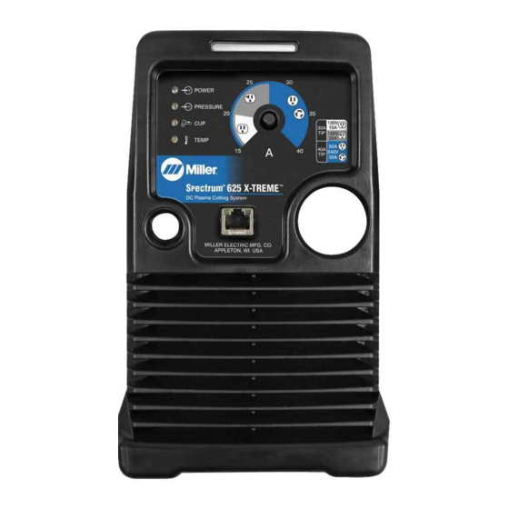
A complete Parts List is available at www.MillerWelds.com SECTION 5 − OPERATION 5-1. Controls POWER PRESSURE TEMP 237 552-A Output Control Power Light Trouble Lights (See Section 6-4) Use control to set cutting output. OM-237 974 Page 18... -
Page 23: Mild Steel Recommended Cut Speed
A complete Parts List is available at www.MillerWelds.com 5-2. Mild Steel Recommended Cut Speed Aluminum and stainless steel cut speeds at these thicknesses may be reduced as much as 30%. Thickness Approximate Travel Speed* Inches Millimeters mm/min 3785 1524 12.7 15.9 *Travel speeds are approximately 80% if maximum. -
Page 24: Plasma Cutting System Practices
A complete Parts List is available at www.MillerWelds.com 5-4. Plasma Cutting System Practices The pilot arc starts immediately when trigger is pressed. Always connect work clamp to a clean, DO NOT start pilot arc without cutting or paint-free location on workpiece, as close to gouging as this shortens the service life cutting area as possible. -
Page 25: Sequence Of Cutting Operation
A complete Parts List is available at www.MillerWelds.com 5-5. Sequence Of Cutting Operation ° Connect work clamp to a clean, paint-free For standard (shielded) cutting, place drag shield on edge location on workpiece, as close to cutting of metal. For extended (non-shielded) cutting, use 1/8 in. area as possible. -
Page 26: Sequence Of Gouging Operation
A complete Parts List is available at www.MillerWelds.com 5-6. Sequence Of Gouging Operation Trigger pilot arc once before starting to gouge. Connect work clamp to a clean, paint-free location on workpiece, as close to cutting area as possible. The pilot arc starts immediately when trigger is pressed. -
Page 27: Sequence Of Piercing Operation
A complete Parts List is available at www.MillerWelds.com 5-7. Sequence Of Piercing Operation The pilot arc starts immediately when trigger is pressed. Connect work clamp to a clean, paint-free Hold torch at an angle to the location on workpiece, as close to cutting workpiece. -
Page 28: Section 6 − Maintenance & Troubleshooting
A complete Parts List is available at www.MillerWelds.com SECTION 6 − MAINTENANCE & TROUBLESHOOTING 6-1. Routine Maintenance Maintain more often Disconnect power during severe conditions. before maintaining. n = Check Z = Change ~ = Clean l = Replace Reference * To be done by Factory Authorized Service Agent Each Section 4-5,... -
Page 29: Wrapper Removal
A complete Parts List is available at www.MillerWelds.com 6-2. Wrapper Removal Turn power, disconnect input power plug from receptacle before working on unit. Check to see that all diagnostic LEDs have stopped flashing before removing wrapper from unit. Wrapper Torx Screws (Fine Thread) Remove Torx screws and slide wrapper off. -
Page 30: Checking Or Replacing Filter Element
A complete Parts List is available at www.MillerWelds.com 6-3. Checking Or Replacing Filter Element Turn power Off, and discon- nect input power plug from receptacle. Check to see that all diagnostic LEDs have stopped flashing before removing wrapper from unit. Remove wrapper from unit (see Section 6-2). -
Page 31: Status/Trouble Lights
A complete Parts List is available at www.MillerWelds.com 6-4. Status/Trouble Lights Diffculty establishing a pilot arc may indicate consumables need to be cleaned or replaced. Light Condition Status/Possible Cause Power Input power is okay. When Power light is on, system is normal if these lights Pressure/Cup/T emp are off. -
Page 32: Checking/Replacing Retaining Cup, Tip, And Electrode
A complete Parts List is available at www.MillerWelds.com 6-6. Checking/Replacing Retaining Cup, Tip, And Electrode Overtightening will strip threads. Do not overtighten retaining cup during assembly. Do not cross-thread parts causing stripping. Use care during torch assembly and parts replacement. Inspect shield cup, tip, and electrode for wear before cutting or whenever cutting speed has been significant- ly reduced. -
Page 33: Troubleshooting Power Source
A complete Parts List is available at www.MillerWelds.com 6-7. Troubleshooting Power Source Trouble Remedy Clean or replace worn consumables as necessary (see torch Owner’s Manual). No pilot arc; difficulty in establishing an arc. Check for damaged torch or torch cable (see torch Owner’s Manual). No cutting output;... -
Page 34: Troubleshooting Torch
A complete Parts List is available at www.MillerWelds.com 6-8. Troubleshooting Torch Trouble Remedy Arc goes on and off while cutting. Torch travel speed too slow; increase travel speed (see Section 5-5). Clean or replace torch consumables as necessary (see Section 6-6). Be sure work clamp is securely attached to workpiece. Arc goes out while cutting. - Page 35 Notes OM-237 974 Page 31...
-
Page 36: Section 7 − Electrical Diagram
SECTION 7 − ELECTRICAL DIAGRAM Figure 7-1. Circuit Diagram OM-237 974 Page 32... - Page 37 235 080-A OM-237 974 Page 33...
-
Page 38: Section 8 − Parts List
SECTION 8 − PARTS LIST 8-1. Recommended Spare Parts Item Dia. Part Mkgs. Description Quantity Recommended Spare Parts ....211120 LABEL, ICE 40T CONSUMABLES . - Page 39 Item Part Turn power Off, and disconnect input power plug from receptacle. Description Check to see that all diagnostic LED’s have stopped flashing before replacing any torch parts. 183 427 Handle Assy, complete (1) 192 059 Main Body (1) The ICE-40T torch is specifically for use only with this plasma cutting unit. 185 833 Switch Assembly w/spring (1)
- Page 40 Notes...
- Page 41 Notes...
- Page 42 Notes...
- Page 43 Effective January 1, 2010 (Equipment with a serial number preface of MA or newer) This limited warranty supersedes all previous Miller warranties and is exclusive with no other Warranty Questions? guarantees or warranties expressed or implied. LIMITED WARRANTY − Subject to the terms and conditions 90 Days —...
- Page 44 Contact the Delivering Carrier to: File a claim for loss or damage during shipment. For assistance in filing or settling claims, contact your distributor and/or equipment manufacturer’s Transportation Department. © ORIGINAL INSTRUCTIONS − PRINTED IN USA 2010 Miller Electric Mfg. Co. 2010−01...
Need help?
Do you have a question about the Spectrum 625 X-TREME and is the answer not in the manual?
Questions and answers