
Related Manuals for FALMEC SIENA F3SN60S1


Summary of Contents for FALMEC SIENA F3SN60S1
- Page 2 CONGRATULATIONS Congratulations and thank you for choosing a Falmec rangehood. To avoid the risks that are always present when you use an electrical appliance it is important that the rangehood is installed correctly and that you read the safety instructions carefully to avoid misuse and hazards.
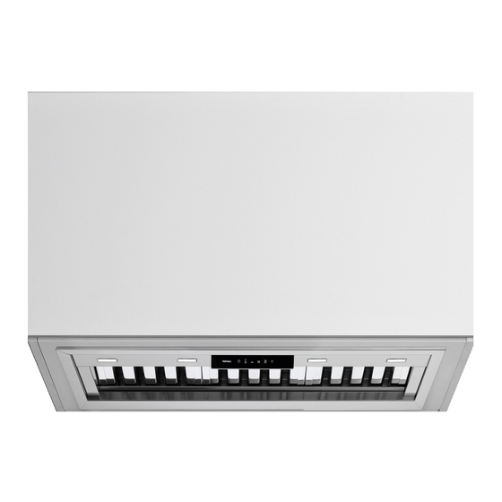
- Page 3 You will be supplied with one of the three hood unit options detailed below. OPTION 1 - INTEGRATED HOOD - ON BOARD HOOD Models include: SIENA F3SN60S1, F3SN90S1 and F3SND90S1 Included in the carton: 1. Main hood housing including control module and lighting 2.
- Page 4 PRODUCT DESCRIPTION & CARTON CONTENTS CARTON 2 - FAN MOTOR UNIT You will be supplied with one of the two fan motor options detailed. OPTION 1 - IN ROOF SOLUTION (FIG.4a) Models include: IR-765 and IR-1140 Unit designed to be located in a roof space and then ducted to an external vent.
-
Page 5: Safety Instructions And Warnings
If the equipment is sold or transferred to another person, make sure that the booklet SAFETY INSTRUCTIONS is also supplied so that the new user can be made aware of the hood’ s operation and relative warnings. AND WARNINGS After the stainless steel hood has been installed, it will need to be cleaned to remove any residues remaining from the protection adhesive as well as any grease and oil stains which, if not removed, can cause irreversible damage to the hood surface. -
Page 6: Operation
OPERATION OPERATING YOUR CONTROL PANEL WITH THE 6 SENSOR TOUCH CONTROL Turning the extraction function ON or OFF: • In standby mode, press button 2 to turn on operating mode, then press buttons 3 through to 5 to change the speed. •... - Page 7 USIN THE RADIO CONTROL 2) - PAIRING THE RADIO CONTROL WITH THE HOOD USING THE ELECTRONIC PUSHBUTTON PANEL WARNINGS!: The radio control is optional. press TIMER on the hood pushbutton panel for 2 seconds: Follow the entire procedure described below if purchased. the red LED lights up.
-
Page 8: Maintenance
GREASE DRIP TRAY MAINTENANCE It is advisable to clean the tray every 15 days. Do not use corrosive, acid or alkaline detergents. For more thorough cleaning, remove the oil collection tray (see figure) and wash it with hot wa- Before cleaning or carrying out maintenance operations, disconnect the ter and washing up liquid. - Page 9 Please follow the installation instructions carefully. Every FALMEC rangehood must be ducted to the external or in-roof motor unit by the use of non-flammable ducting. The rangehood must not be ducted into a wall cavity or a ceiling space where a build-up of grease can occur and become a potential fire risk.
- Page 10 SERVICING OF REMOTE MOTORS The installation and fitting of the external or in-roof motor should be done in such a way that will allow the unit to be removed if service is required. Additional costs incurred in the removal, such as damage to walls and roofs, are not covered under warranty.
- Page 11 PART 1: HOOD INSTALLATION GUIDE - INTEGRATED HOODS - ON BOARD MOTOR ON BOARD HOOD Models include SIENA F3SN60S1, F3SN90S1 and F3SND90S1 WARNING DIMENSIONS ARE ACCURATE AT THE TIME OF PRINTING, PR KITCHEN & WASHROOM SYSTEMS PTY LTD RESERVES THE RIGHT TO CHANGE SPECIFICATIONS WITHOUT NOTICE.
- Page 12 PART 1: HOOD INSTALLATION GUIDE - INTEGRATED HOODS - ON BOARD MOTOR STEP 4: The returns on the main body are now exposed. These are used to fix the main body on to the cabinetry. Place the hood in the cabinet in the level position ensuring that the controls and display will be visible when standing in front of the unit.
- Page 13 600- 650mm...
- Page 15 SIENA 60 / 90 13 kg All measurements in mm 505 / 815 560 / 870 512 / 822 HOLE MEASUREMENTS FOR INSTALLATION...
- Page 16 13 kg HOLE MEASUREMENTS FOR INSTALLATION...
- Page 17 PART 1: HOOD INSTALLATION GUIDE - INTEGRATED HOODS - REMOTE MOTOR INTEGRATED HOOD Models include MILANO F3ML60S1, F3ML90S1, F3MLD90S1, F3MLD12S1 and GENOVAF3GV12S1 WARNING DIMENSIONS ARE ACCURATE AT THE TIME OF PRINTING, PR KITCHEN & WASHROOM SYSTEMS PTY LTD RESERVES THE RIGHT TO CHANGE SPECIFICATIONS WITHOUT NOTICE. FOR BUILDING PURPOSES THE UNIT SHOULD BE PROVIDED TO THE CABINET MAKER / BUILDER / KITCHEN DESIGNER FOR EXACT MEASUREMENTS.
- Page 18 PART 1: HOOD INSTALLATION GUIDE - INTEGRATED HOODS - REMOTE MOTOR STEP 6: Connect the hood outlet to the 200 mm flexi ducting leading to the in-roof or external motor. STEP 7: Attach the male plug of the rangehood unit to the main power supply. Note to electricians: Standard 10 amp general power outlet (GPO) required.
- Page 19 600- 650mm...
- Page 21 MILANO 13 kg HOLE MEASUREMENTS FOR INSTALLATION...
- Page 22 MILANO 90 / 120 13 kg 804 / 1094 870 / 1160 814 / 1104 HOLE MEASUREMENTS FOR INSTALLATION...
- Page 23 PART 1: HOOD INSTALLATION GUIDE - WALL HUNG WALL HUNG CANOPY Models include LATINA F5LT90S1, TREVISO F5TV90S1, ROMA F5RM90B1, MODENA F5ME12S1 and TRENTO F5TN12S1 WARNING DIMENSIONS ARE ACCURATE AT THE TIME OF PRINTING, PR KITCHEN & WASHROOM SYSTEMS PTY LTD RESERVES THE RIGHT TO CHANGE SPECIFICATIONS WITHOUT NOTICE. FOR BUILDING PURPOSES THE UNIT SHOULD BE PROVIDED TO THE CABINET MAKER / BUILDER / KITCHEN DESIGNER FOR EXACT MEASUREMENTS.
- Page 24 PART 1: HOOD INSTALLATION GUIDE - WALL HUNG STEP 7: Insert the flue extension into the main flue cover. Fasten to the hood body using the screws provided (V5). Slide the extension until it reaches the desired height. STEP 8: Place the white flue bracket on the wall, verify the horizontal alignment with a spirit level and mark the 2 drilling points at the ends.
- Page 25 PART 1: HOOD INSTALLATION GUIDE - WALL HUNG (x2) ø 6 ø 6 mm ø 6 (x2)
- Page 26 PART 1: HOOD INSTALLATION GUIDE - ISLAND CANOPIES - REMOTE MOTOR ISLAND HUNG CANOPY Models include TREVISO F7TV90S1, ROMA F7RM90S1 and TRENTO F7TN12S1 WARNING DIMENSIONS ARE ACCURATE AT THE TIME OF PRINTING, PR KITCHEN & WASHROOM SYSTEMS PTY LTD RESERVES THE RIGHT TO CHANGE SPECIFICATIONS WITHOUT NOTICE. FOR BUILDING PURPOSES THE UNIT SHOULD BE PROVIDED TO THE CABINET MAKER / BUILDER / KITCHEN DESIGNER FOR EXACT MEASUREMENTS.
- Page 27 PART 1: HOOD INSTALLATION GUIDE - ISLAND CANOPIES - REMOTE MOTOR STEP 3 Insert the extension flue into the main piece and secure at the required height with masking (x4) tap. Ø8 Ø8 STEP 4: Ø8 ø8 Slide the stainless steel chimney covers up and secure to the bracket.
- Page 28 STEP 3 Insert the extension flue into the main piece and secure at the required height with masking tap. (x4) Slide the stainless steel chimney covers up and secure to the bracket. You may need to drill some new holes through the cover and bracket to secure the chimney cover depending on desired length.
- Page 29 REMOTE MOTOR SOLUTIONS EXTERNAL ROOF SOLUTION 765, 1140 & 2010m3/h 1. Fan power supply connects to internal hood unit 2. Tile or metal roof flashing (optional accessory) 3. Rigid duct mount (optional accessory) 4. 200mm flexi ducting (attached to internal hood unit)* *Advise to include gentle bend in duct run as well ensuring ducting is pulled tight and excess removed.
- Page 30 PART 2: MOTOR INSTALLATION GUIDE IN ROOF SOLUTION Mounting Bracket Outlet Positioning your In-Roof Unit: It is recommended that the In-Roof motor unit be mounted in a roof space or wall cavity. Please ensure that the In-Roof motor unit is positioned in an environment that is free of other gases to enable an efficient expulsion of the cooking by-products and to ensure that back draft of...
- Page 31 PART 2: MOTOR INSTALLATION GUIDE EXTERNAL ROOF SOLUTION - METAL ROOF INSTALLATION Inspection: Ensure the unit has arrived in good condition and that the impeller will spin freely. This product is designed to be installed on a roof up to 45° pitch. 1.
- Page 32 PART 2: MOTOR INSTALLATION GUIDE EXTERNAL ROOF SOLUTION - TILE ROOF INSTALLATION Inspection: Ensure the unit has arrived in good condition and that the impeller will spin freely. This product is designed to be installed on a roof up to 45° pitch. 1.
- Page 33 PART 2: MOTOR INSTALLATION GUIDE EXTERNAL WALL SOLUTION Inspection: Ensure the unit has arrived in good condition and that the impeller will spin freely. Installation: 1. Installation of this product should be carried out by appropriately qualified persons. 2. This fan is designed for connection to 200 mm duct using duct tape or clamps. 3.
- Page 34 EW-765 / EW-1140 SPECIFICATIONS 4 holes All measurements in mm EW-2010 SPECIFICATIONS 4 holes All measurements in mm...
- Page 35 DESIGNER WARRANTY All FALMEC Designer range hoods and remote motors come with a 3 year parts and labour warranty. PRKS will correct, free of charge, any defects in material or workmanship for the period of 3 years, subject to the terms of our warranty stated below.
- Page 36 PROFESSIONAL WARRANTY FALMEC Professional series hoods are covered under the same 3 year parts and labour warranty as stated for the Designer series models and as such incorporates the same terms and conditions, benefits and statutory rights however the following...
- Page 37 NOTES...
Need help?
Do you have a question about the SIENA F3SN60S1 and is the answer not in the manual?
Questions and answers