Advertisement
Quick Links
Advertisement

Related Manuals for FALMEC MILANO+


Summary of Contents for FALMEC MILANO+
- Page 1 INSTALLATION MANUAL Milano Genova 120 falmecau.com...
- Page 2 CONGRATULATIONS Congratulations and thank you for choosing a Falmec rangehood. To avoid the risks that are always present when you use an electrical appliance it is important that the rangehood is installed correctly and that you read the safety in- structions carefully to avoid misuse and ha- zards.
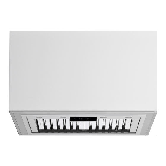
- Page 3 PRODUCT DESCRIPTION & CARTON CONTENTS CARTON 1 - HOOD UNIT INTEGRATED HOOD - REMOTE MOTOR Models include: MILANO FP3ML60S2, FP3ML90S2, MILANO FP3MLD90S2, FP3MLD12S2 GENOVA FP3GV12S2 Included in the carton: 1. Main hood housing including control module and lighting 2. Baffl e fi lters 3.
- Page 4 MILANO + 56 / 87 FP3ML60S2 FP3ML90S2 379 / 665 505 / 815 541 / 851 541 / 851 512 / 822 EN - HOLE MEASUREMENTS FOR INSTALLATION IT - MISURE FORO PER INCASSO...
- Page 5 MILANO + 87 / 116 DEEP FP3MLD90S2 FP3MLD12S2 584 / 870 815 / 1101 851 / 1137 851 / 1137 824 / 1110 EN - HOLE MEASUREMENTS FOR INSTALLATION IT - MISURE FORO PER INCASSO...
- Page 6 GENOVA + 116 FP3GV12S2 1101 1137 1137 1110 EN - HOLE MEASUREMENTS FOR INSTALLATION IT - MISURE FORO PER INCASSO...
- Page 7 STEP 1: Minimum distance by cooktop. STEP 2: Wall unit hole. STEP 3: You push the hood in wall unit hole.
- Page 8 STEP 4: You screw the blocking devices. STEP 5: Connect the hood outlet (in the top or back ducted position) to 150mm ducting leading to an external output. DUCTED POSITION CAUTION CAUTION ATTENTION! ONLY ON MILANO + DEEP DUCTED POSITION FOR BACK DUCTED POSITION...
- Page 9 STEP 6: Attach the male plug of the rangehood unit to the main power supply. STEP 7: Assembling the metal fi lters. ATTENTION! ATTENTION! FOR BACK DUCTED ONLY FOR BACK DUCTED ONLY POSITION ON MILANO + 87 DEEP POSITION ON MILANO + 87 DEEP...
- Page 10 SEQUENCE FOR REMOVING THE HOOD STEP 8: STEP 10: Remove the metal filters. With your finger enter the hole and pull the lever to unlock the stop. STEP 9: Remove the cover caps.
-
Page 11: Safety Instructions And Warnings
SAFETY INSTRUCTIONS Before installing the hood, check that the electrical mains power supply corresponds with what is report- AND WARNINGS ed on the identification plate located inside the hood. Installation operations are to be carried If the supply cord is damaged, it must be replaced by out by skilled and qualified installers in ac- the manufacturer, its service agent or similarly qualified cordance with the instructions in this booklet and... -
Page 12: Intended Use
INTENDED USE INSTALLATION only intended for qualified personnel The equipment is solely intended to be used to extract fumes generated from cooking food in Before installing the hood, carefully read the chapter "SAFETY non-professional domestic kitchens: any other INSTRUCTIONS AND WARNINGS". use is improper. - Page 13 USING THE RADIO CONTROL (OPTIONAL) Speed 2 activation WARNINGS! Speed 3 activation Place the hood away from sources of electromagnetic waves (e.g. micro- wave ovens), which could interfere with the radio control and with the hood electronics. Speed 4 activation for 10 minutes only The maximum operating distance is 5 metres, that may vary according to the presence of electromagnetic interferences.
-
Page 14: Maintenance
LIGHTING RADIO CONTROL CODE CHANGE With only one radio control, go directly to point 2. The range hood is equipped with high effi ciency, low consumption LED light. With several radio controls in the same room, a new code can be created by following the procedure below. - Page 15 The Flexi ducting is designed to ensure optimum performance for your range- INTEGRATED HOOD hood. Please follow the installation instructions carefully. Every FALMEC rangehood must be ducted to the external or in-roof motor unit Models include MILANO: by the use of non-flammable ducting. The rangehood must not be ducted into a...
- Page 16 REMOTE MOTOR SOLUTIONS Ø 403 / 445 EXTERNAL ROOF SOLUTION 765, 1140 & 2010m 1. Fan power supply connects to internal hood unit. 2. Tile or metal roof flashing (optional accessory). 3. Rigid duct mount (optional accessory). 4. 200mm flexi ducting (attached to internal hood unit)*. * Advise to include gentle bend in duct run as well ensuring ducting is pulled tight and excess removed.
- Page 17 PART 2: MOTOR INSTALLATION GUIDE EXTERNAL ROOF SOLUTION - METAL ROOF INSTALLATION Inspection: IN ROOF SOLUTION Ensure the unit has arrived in good condition and that the impeller will spin freely. Positioning your In-Roof Unit: This product is designed to be installed on a roof up to 45° pitch. It is recommended that the In-Roof motor unit be mounted in a roof space or wall cavity.
- Page 18 EXTERNAL ROOF SOLUTION - TILE ROOF INSTALLATION EXTERNAL WALL SOLUTION Inspection: Inspection: Ensure the unit has arrived in good condition and that the impeller will spin Ensure the unit has arrived in good condition and that the impeller will spin freely.
- Page 19 EW-765 / EW-1140 SPECIFICATIONS 4 holes All measurements in mm EW-2010 SPECIFICATIONS 4 holes All measurements in mm...
- Page 20 YOUR STATUTORY RIGHTS FALMEC products fully assures all customers that our goods come with guaran- All FALMEC Professional range hoods come with a 3 year parts and labour war- tees that cannot be excluded under the Australian Consumer Law. You are enti- ranty.
- Page 21 NOTE - NOTES...
- Page 22 NOTE - NOTES...
- Page 23 NOTE - NOTES...
Need help?
Do you have a question about the MILANO+ and is the answer not in the manual?
Questions and answers