Table of Contents
Advertisement
Quick Links
Advertisement
Table of Contents

Related Manuals for sauter TC 1250-0.1 F


Summary of Contents for sauter TC 1250-0.1 F
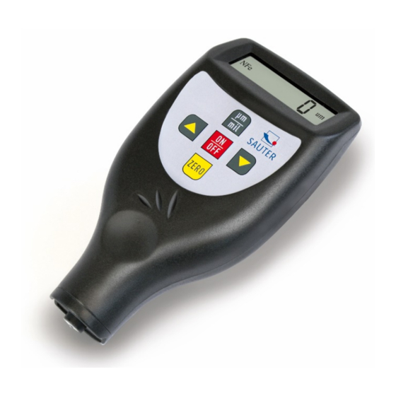
- Page 1 Sauter GmbH Ziegelei 1 Tel: +49-[0]7433- 9933-199 D-72336 Balingen Fax: +49-[0]7433-9933-149 E-Mail: info@sauter.eu Internet: www.sauter.eu Instruction Manual Digital Coating Thickness Gauge SAUTER TC Version 1.2 08/2017 Illustration: TC 1250-0.1FN PROFESSIONAL MEASURING TC -BA-e-1712...
-
Page 2: Table Of Contents
Instruction Manual Digital Coating Thickness Gauge Thank you for buying a SAUTER digital Coating Thickness Gauge. We hope you are pleased with your high quality Thickness Gauge with its big functional range. If you have any queries, wishes or helpful suggestions, do not hesitate to call our service number. -
Page 3: Features
This coating thickness gauge is small in size, light in weight and easy to carry. Al- though it is complex and advanced, it is convenient to operate. Its ruggedness will allow many years of use if all the instructions are followed carefully. Please keep this instruction manual always within reach! Annotation: It is strongly recommended to adjust the new instrument before the first use, as described in paragraph 5. - Page 4 Scope of delivery: - Carrying case - Instruction manual According to types: 1. Incorporated sensor at F model: TC 1250-0.1 F, with button F/N 2. Incorporated sensor at N model: TC 1250-0.1 N, with button F/N 3. Incorporated sensor at FN model: TC 1250-0.1 FN, without button F/N u.
-
Page 5: Front Panel Description
3 Front Panel description Modell TC-.F und TC-N Modell TC-FN (Kombi-Modell) 3-11 3-10 3-10 3-1 Sensor: F, N or FN 3-2 Display 3-3 Zero- key 3-4 Plus- key 3-5 Minus- key 3-6 Power on/ Power off- key (multi-functional) 3-7 µm/ mil conversion key (shortcut key) 3-8 Battery compartment/ cover 3-9 S/C- key (single/ continuous) 3-10 Jack for RS-232C interface... -
Page 6: Zero- Adjustment (Calibration)
d) If an accuracy of measurement is suspected, we recommend calibrating the in- strument before measuring, as described in part 5. e) The instrument can be switched off by pressing the Power- key 3-6. Or it will switch itself off 50 seconds after the last key operation. f) The measurement unit can be indicated in `µm` or `mil`. -
Page 7: Battery Replacement
6 Battery replacement a) If the battery symbol ``+/-`` appears on the display, the batteries should be re- placed. b) Battery cover 3-8 has to be removed and batteries have to be taken out. c) Batteries (4x1.5V AAA/UM-4) have to be installed correctly into the case. Please pay attention to polarity! d) If the instrument is not going to be used for an extended period, batteries have to be removed. -
Page 8: 10 Notes
The Power- on/ Power- off key 3-6 has to be pressed and not released until `CAL` appears on the display. It lasts about 5 seconds from the last key operation until CAL will appear. The sensor 3-1 has to be placed carefully onto the respective base material. Then the Zero key 3-3 has to be pressed, accompanied by a “beep”...