Table of Contents
Advertisement
Quick Links
Advertisement
Table of Contents

Related Manuals for Monoprice 30994


Summary of Contents for Monoprice 30994
- Page 1 MP Mini Deluxe SLA LCD High Resolution Resin 3D Printer P/N 30994 User's Manual...
-
Page 2: Table Of Contents
CONTENTS SAFETY WARNINGS AND GUIDELINES ............................4 INTRODUCTION ........................................ 6 FEATURES ..........................................6 CUSTOMER SERVICE ....................................6 PACKAGE CONTENTS ....................................7 MINIMUM SYSTEM REQUIREMENTS ............................. 7 RECOMMENDED ITEMS .................................... 7 PRODUCT OVERVIEW ....................................8 Front View........................................8 Rear View ........................................8 INSTALLATION ........................................ - Page 3 Configure Machine ....................................23 Configure Slicing Profile ................................. 24 Slicing a Model ......................................26 Connecting the Software to the Printer .......................... 26 SPECIFICATIONS ......................................27 TECHNICAL SUPPORT ....................................28 REGULATORY COMPLIANCE ................................28 Notice for FCC ......................................28 Notice for Industry Canada ................................29...
-
Page 4: Safety Warnings And Guidelines
SAFETY WARNINGS AND GUIDELINES Please read this entire manual before using this device, paying extra attention to these safety warnings and guidelines. Please keep this manual in a safe place for future reference. This device is intended for indoor use only. ... - Page 5 Take care to prevent damage to the power cord. Do not allow it to become crimped, pinched, walked on, or become tangled with other cords. Ensure that the power cord does not present a tripping hazard. Never unplug the unit by pulling on the power cord. Always grasp the connector head or adapter body.
-
Page 6: Introduction
If you have any problem with your order, please give us an opportunity to make it right. You can contact a Monoprice Customer Service representative through the Live Chat link on our website www.monoprice.com during normal business hours (Mon-Fri: 5am-7pm PT, Sat-Sun: 9am-... -
Page 7: Package Contents
PACKAGE CONTENTS Please take an inventory of the package contents to ensure you have all the items listed below. If anything is missing or damaged, please contact Monoprice Customer Service for a replacement. 1x 3D printer 1x Latex gloves (pair) -
Page 8: Product Overview
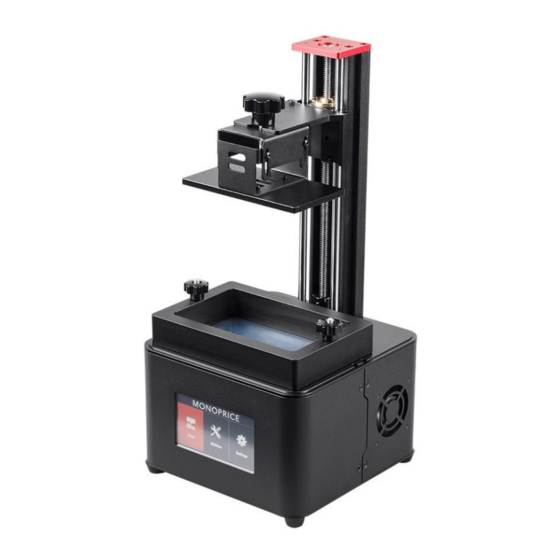
PRODUCT OVERVIEW Front View 1. Red anti-wobble cover 2. Machined aluminum build plate 3. Vat locking screw 4. LCD touchscreen 5. Double rail anti-wobble guide system 6. Re-usable resin vat 7. Triple cooling fan Rear View 9. Aluminum vertical beam 10. -
Page 9: Installation
INSTALLATION MP Creation Workshop is a .NET 3.5 application written in the C# programming language. This is native to the Windows® operating system, but also runs on many versions of Linux®/Posix using the Mono Framework (http://www.mono-project.com/Main_Page). You will need to download and install the Mono Framework when using MP Creation Workshop on a Linux-based system. - Page 10 5. Click the gears icon in the upper left corner, then ensure that the Configured Displays value is set to 2560 x 1440. 6. Close the software, then restart it. The software will remember the settings you saved, so you don't have to configure it each time. 7.
- Page 11 9. Once the sliced file is created, copy it to a USB flash drive for use with the printer. 10. Insert the USB flash drive into the USB port on the printer's rear panel, then flip the power switch to turn the printer on. 11.
-
Page 12: Mp Creation Workshop Reference
14. Touch the button to begin printing. MP CREATION WORKSHOP REFERENCE Main Screen The following table shows the functions of the buttons on the Main Screen. Button Function Click this button to open object files in the .STL, .OBJ, .3DS, or .AMF formats. You can also open scene files with the .CWS extension Click to save the current object as a .STL or .CWS file. - Page 13 Button Function Click to establish a connection between the printer and the computer. If the printer and computer are already connected, the button will be grayed out. Click to disconnect the printer and computer. If the printer and computer are already disconnected, the button will be grayed out.
-
Page 14: Loading A File
Loading a File Click the button to load a .STL, .OBJ, .3DS, or .AMF object file. You can load multiple objects and manipulate them independently. You can also open scene files with .CWS file extension, which can contain multiple objects and supports. Scene View... -
Page 15: Move View
The Scene View allows you to manipulate various aspects of the scene. Selecting a Model: You can select a model by double-clicking on the model or by clicking the name in the Scene View list. Removing a Model: You can remove a model by right-clicking the name in the Scene View list and selecting the Remove option. -
Page 16: Mirroring Objects
Place on Platform: Click the button to place the selected object on the platform. Center: Click the button to center the selected object in the X and Y axes. Auto Arrange: Click the button to automatically arrange all objects on the platform. -
Page 17: Scaling Objects
Scaling Objects You can scale the selected object to make it larger or smaller in any or all axes by clicking the Plus (+) and Minus (-) buttons for the All, X, Y, and/or Z axes. Alternatively, you can type a value directly into the box between the Plus (+) and Minus (-) buttons. -
Page 18: Rotating Objects
Rotating Objects You can rotate the selected object by clicking the Plus (+) and Minus (-) buttons in the X, Y, and/or Z axes. You can also type a value directly into the box between the Plus (+) and Minus (-) buttons. -
Page 19: View Options
View Options Click the button to enable 50% Alpha-Blending, which allows you to see through the objects in the scene to see the geometry. Click the button to show the Slice Preview, which allows you to view the 3D view of the currently selected slice layer as selected by the horizontal bar. -
Page 20: Working With Model Support Tools
Working with Model Support Tools Supports are sometimes required to properly attach a model to the build plate. Because of the nature of photopolymer printing, the lower layers must be supported unless it has lower layers larger than the upper layers. ... -
Page 21: Saving A Scene
generate supports on downward facing polygons, check the boxes under Support General and Generate Only on Downward. Adaptive Supports: You can add supports to areas in the model that are unsupported. There are two algorithms to help you accomplish this. Saving a Scene After one or more models have been loaded and manipulated on the build platform, you can click the... -
Page 22: Control Screen
horizontal scroll bar at the bottom of the screen to select individual layers. The button in the lower left corner allows you to turn the projector on or off to expose the selected layer. This can be useful for checking the positioning of the vat. The GCode View allows you to see the GCode generated during the slicing operation. -
Page 23: Configure Machine
Show Blank: Projects a black screen that will not cure resin instantly. Hide: This option hides the slice projection screen, allowing the projector to display the main desktop background. Edit Commands: This option allows you to edit commands to control the projector. The fields beneath this option are not recommended for use. -
Page 24: Configure Slicing Profile
LCD controls. Typically, only one display is used. MP Creation Workshop can support two projectors, each with the same resolution and projection size, either in a horizontal or vertical format. Machine Controls: The column of check boxes on the right side of the screen allows you to customize the controls that appear on the Manual Control screen. - Page 25 different resolutions and for different resins. Click the Create button to create a new profile. Click the Delete button to delete the selected profile. Slice Thickness: This field sets the thickness of each slice in millimeters. The default is 0.05mm (20 slices per millimeter). ...
-
Page 26: Slicing A Model
X/Y Pixel Offset: This X/Y value allows you to offset the rendered image by a pixel amount. Build Direction: This allows you to specify if the machine builds the model from the Top Down or from the Bottom Up. For a Bottom Up type machine, this is used to peel the model from the bottom of the build vat, sometimes in conjunction with a tilt/slide. -
Page 27: Specifications
SPECIFICATIONS Model 30994 Extruder System 405 nm UV Lamp, LCD Curing System Insulated Cover Total Blinding Hood Maximum Print Area 4.8" x 2.7" x 7.1" (121 x 69 x 180 mm) Software MP Creation Workshop Filament Diameter/Light 405 nm UV Light... -
Page 28: Technical Support
TECHNICAL SUPPORT Monoprice is pleased to provide free, live, online technical support to assist you with any questions you may have about installation, setup, troubleshooting, or product recommendations. If you ever need assistance with your new product, please come online to talk to one of our friendly and knowledgeable Tech Support Associates. -
Page 29: Notice For Industry Canada
user is encouraged to try to correct the interference by one or more of the following measures: Reorient or relocate the receiving antenna. Increase the separation between the equipment and receiver. Connect the equipment into an outlet on a circuit different from that to which the receiver is connected.
Need help?
Do you have a question about the 30994 and is the answer not in the manual?
Questions and answers