
Related Manuals for Media5 Mediatrix C710


Summary of Contents for Media5 Mediatrix C710
- Page 1 Discover the Power of Hardware Installation Guide Mediatrix C7 Series Product Version 2.0 Document Revision 02 March 27, 2013 RoHS COMPLIANT 2002/95/EC...
- Page 2 – without the express written permission of the publisher. Media5 Corporation reserves the right to revise this publication and make changes at any time and without the obligation to notify any person and/or entity of such revisions and/or changes.
-
Page 3: Table Of Contents
Warning Definition ............................... x Other Conventions ..............................x SCN vs PSTN................................x Standards Supported ..............................x Obtaining Documentation ..........................xi Media5 Web Site .................................xi Media5 Download Portal .............................xi Documentation Feedback ............................xi End User Technical Support........................xi Chapter 1 Overview ..........................1 Overview...............................1... - Page 4 Contents Connecting Cables ..............................11 Chapter 3 Powering on the Mediatrix C7 Series ................13 IP Address Discovery or Configuration.......................13 Dynamic IPv4 Address Discovery ..........................13 Default Static IPv4 Address Configuration ........................ 14 IPv6 Link Local Address Configuration ........................15 Vocal Unit Information ...............................
- Page 5 Hardware Installation Guide Appendix C Glossary ..........................33 Appendix D List of Acronyms ....................... 37 Mediatrix C7 Series...
- Page 6 Contents Mediatrix C7 Series...
-
Page 7: Preface
R E F A C E About this Manual Thank you for purchasing the Mediatrix C7 Series from Media5 Corporation. Introduction The Mediatrix C7 Series are multi-function devices combining VoIP Analog Adapter, Gateway and QoS control in a secure and powerful platform. -
Page 8: Document Objectives
Preface - About this Manual Document Objectives Document Objectives The Mediatrix C7 Series Hardware Installation Guide provides technical information on how to physically install the Mediatrix C7 Series. It also describes the cabling required for the Mediatrix C7 Series device. The information included in this guide consists of: ... -
Page 9: Document Structure
Document Structure Hardware Installation Guide Document Structure The Mediatrix C7 Series Hardware Installation Guide contains the following information. Table 2: Mediatrix C7 Series Hardware Installation Guide Chapter/Appendices Title Summary “Chapter 1 - Overview” on page 1 Provides a brief description of the Mediatrix C7 Series. -
Page 10: Document Conventions
SCN vs PSTN In Media5’ and other vendor’s documentation, the terms SCN and PSTN are used. A SCN (Switched Circuit Network) is a general term to designate a communication network in which any user may be connected to any other user through the use of message, circuit, or packet switching and control devices. -
Page 11: Obtaining Documentation
These sections explain how to obtain documentation from Media5. Media5 Web Site Media5 offers the latest version of its products’ documentation on its web site. You will thus be able to access and download the most current Media5 documentation. Follow this link: http://www.media5corp.com/en/... - Page 12 Preface - About this Manual End User Technical Support Mediatrix C7 Series – Digital Gateway...
-
Page 13: Chapter 1 Overview
H A P T E R Overview This chapter describes the Mediatrix C7 Series connectors and indicators. Overview Provider-specific profiles ensure that the Mediatrix C7 Series is a genuine plug and play solution. It offers a low total cost of ownership as it reduces installation and maintenance costs. Moreover, the Mediatrix C7 Series integrates features such as TLS, SRTP, and HTTPS designed to bring enhanced security for network management, SIP signalling and media transmission aspects. -
Page 14: Front Indicators And Connectors
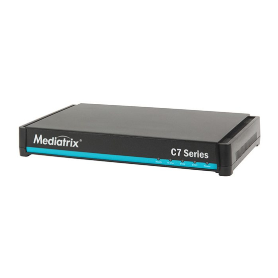
Chapter 1 - Overview Mediatrix C7 Series Connectors and Indicators Front Indicators and Connectors “Indicators (LEDs)” on page 16 for a description of the LED patterns the Mediatrix C7 Series may have and the states they represent. Figure 1 shows the five visual indicators located on the front of the Mediatrix C7 Series. Figure 1: Mediatrix C7 Series Front Panel Indicators SERIES Ready... - Page 15 Mediatrix C7 Series Connectors and Indicators Hardware Installation Guide Table 4 describes the rear panel connections (from left to right). Table 4: Rear Connections of the Mediatrix C7 Series Connection Description Power connector External 12 Vdc power supply. The Mediatrix C7 Series may use one of two power supply units: •...
- Page 16 Chapter 1 - Overview Mediatrix C7 Series Connectors and Indicators Mediatrix C7 Series – Digital Gateway...
-
Page 17: Chapter 2 Installation
H A P T E R Installation This chapter describes the installation of the Mediatrix C7 Series. Planning the Installation Before installing the Mediatrix C7 Series, you should complete the following tasks: Create a network diagram (see section “Network Diagram” on page ... -
Page 18: Site Log
Planning the Installation Site Log Media5 recommends that you maintain a site log to record all actions relevant to the Mediatrix C7 Series, such Installation: Print a copy of the installation checklist and insert it into the site log. -
Page 19: Safety Recommendations
Safety Recommendations Hardware Installation Guide Safety Recommendations The following are safety recommendations and best practices to follow when working with the Mediatrix C7 Series. Maintaining Safety with Electricity Warning: Do not work on the Mediatrix C7 Series, connect or disconnect cables during periods of lightning activity. -
Page 20: Required Mounting Tools And Equipment
Chapter 2 - Installation Required Mounting Tools and Equipment Required Mounting Tools and Equipment You will need the following tools and parts to properly install the Mediatrix C7 Series: ESD-preventive wrist strap. In addition, you might need the following external equipment: ... -
Page 21: Wiring Requirements
Location and Mounting Requirements Hardware Installation Guide Wiring Requirements Make sure that the telephone wiring, LAN and WAN cables reach the device and can be dressed in a manner that is safe for the wiring, does not pull or create lateral stress on the connectors on the device, and does not present a trip hazard to personnel working in the vicinity of the equipment. -
Page 22: Wall-Mounting
Chapter 2 - Installation Location and Mounting Requirements Wall-Mounting To wall-mount the Mediatrix C7 Series: Disconnect all of the cables from the Mediatrix C7 Series before mounting. Ensure that the wall you are using is smooth, flat, dry and sturdy. Attach a piece of plywood, approximately 250 mm x 200 mm x 12 mm (10 inches x 8 inches x 0.5 inches) securely to the wall, if necessary. -
Page 23: Hardware Installation
Hardware Installation Hardware Installation Guide Hardware Installation This section describes how to set the connectors of the Mediatrix C7 Series. Caution: The Mediatrix C7 Series must be installed on a circuit equipped with a breaker so that you can easily power the unit off if required. Warning: To avoid electrical shock, apply the following instructions: •... - Page 24 Chapter 2 - Installation Hardware Installation Use a standard telecommunication cord with a minimum of 26 AWG wire size. You can either use a crossover or straight Ethernet cable because it performs automatic MDI / MDIX detection. See “RJ-45 Cable” on page 29 for more details.
-
Page 25: Powering On The Mediatrix C7 Series
The default configuration is set so that the unit can be directly plugged into a network and provisioned with a DHCP server. Media5 strongly recommends to set your DHCP server before installing the unit on the network. This way, you know the IP address associated with a particular unit. -
Page 26: Default Static Ipv4 Address Configuration
Chapter 3 - Powering on the Mediatrix C7 Series IP Address Discovery or Configuration The Mediatrix C7 Series should be already running. If not, power it on by connecting the other end of the power adaptor to an electrical earthed socket-outlet. The electrical outlet must be installed near the Mediatrix C7 Series so that it is easily accessible. -
Page 27: Ipv6 Link Local Address Configuration
IP Address Discovery or Configuration Hardware Installation Guide This procedure is called a partial reset. After a partial reset is performed, the Mediatrix C7 Series uses the default IP address 192.168.0.1/24. Refer to “Partial Reset” on page 19 for details on the partial reset procedure. -
Page 28: Verifying The Installation
Chapter 3 - Powering on the Mediatrix C7 Series Indicators (LEDs) Table 5: Vocal Unit Information (Continued) Digits to Dial Information Vocally Sent by the Mediatrix C7 Series *#*1 MAC address of the Mediatrix C7 Series. Verifying the Installation There are a few ways to verify that the Mediatrix C7 Series is properly connected to the IP network and is working: ... -
Page 29: Led Patterns - Default Behaviour
Indicators (LEDs) Hardware Installation Guide Table 6: LED Patterns (Continued) Condition Description LED Pattern UpdateInProgress A firmware pack is downloaded into the unit All LEDs: and written to persistent storage. • cycling from left to right, individually blinking 1Hz, 33% duty UpdateFailed Triggered after a failure of a firmware pack... -
Page 30: Reset/Default Button
Chapter 3 - Powering on the Mediatrix C7 Series RESET/DEFAULT Button Table 7: Default LED Behaviour (Continued) LED Type Condition Behaviour Lines Idle and Unlocked Steady OFF Lines InUse and Unlocked Steady ON In Use Shutting Down Steady yellow Locked Blinking yellow, 1 Hz, 50% duty All lines are enabled Steady ON... -
Page 31: At Start-Time
RESET/DEFAULT Button Hardware Installation Guide At Start-Time You can use the RESET/DEFAULT button at start-time – you power the unit off, and then depress the button until the LEDs stop blinking and remain ON. This applies the “Factory Reset” procedure (see “Factory Reset”... -
Page 32: Management Choices
Chapter 3 - Powering on the Mediatrix C7 Series Management Choices To trigger the Factory Reset: Power the Mediatrix C7 Series off. Insert a small, unbent paper clip into the Reset / Default hole located at the rear of the Mediatrix C7 Series. -
Page 33: Standards Compliance And Safety Information
P P E N D I X Standards Compliance and Safety Information This Appendix lists the various standards compliance of the Mediatrix C7 Series. Standards Supported The Mediatrix C7 Series complies to the following standards: Table 10: Standards Compliance Category Specification Agency approvals •... -
Page 34: Disclaimers
PARLIAMENT (RTTE DIRECTIVE) is given. Any unauthorized modification of the product voids this declaration. For a copy of the original signed Declaration Of Conformity please contact Media5 at the above address. RoHS Declaration Of Compliance The Mediatrix C7 Series is in compliance with the Council Directive 2002/95/EC on the restriction of the use of certain hazardous substances in electrical and electronic equipment. -
Page 35: Rohs China
Disclaimers Hardware Installation Guide RoHS China Mediatrix C7 Series – Digital Gateway... -
Page 36: Altitude Of Operation
Appendix A - Standards Compliance and Safety Information Disclaimers Altitude of Operation Translated from Chinese as "Used only at altitudes not more than 2000m above sea level" or similar. Mediatrix C7 Series – Digital Gateway... -
Page 37: Translated Warning Definition
Translated Warning Definition Hardware Installation Guide Translated Warning Definition The following information provides an explanation of the symbols which appear on the Mediatrix C7 Series and in the documentation for the product. Warning: Means danger. You are in a situation that could cause bodily injury. Before you work on any equipment, you must be aware of the hazards involved with electrical circuitry and familiar with standard practices for preventing accidents. -
Page 38: Safety Warnings
Appendix A - Standards Compliance and Safety Information Safety Warnings Safety Warnings This section lists the following safety warnings: Circuit Breaker (15A) Warning TN Power Warning Product Disposal Warning No. 26 AWG Warning ETH2, ETH1, and FXS Connectors ... -
Page 39: Circuit Breaker (15A) Warning
Safety Recommendations Hardware Installation Guide Circuit Breaker (15A) Warning Warning: This product relies on the building's installation for short-circuit (overcurrent) protection. Ensure that a fuse or circuit breaker no larger than 120 VAC, 15A U.S. (240 VAC, 10A international) is used on the phase conductors (all current-carrying conductors). - Page 40 Appendix A - Standards Compliance and Safety Information Safety Recommendations unsafe. Caution: When using this equipment, basic safety precautions should always be followed to reduce the risk of fire, electric shock and injury to persons, including the following: • Do not use this product near water, for example, near a bath tub, wash bowl, kitchen sink or laundry tub, in a wet basement or near a swimming pool.
-
Page 41: Cabling Considerations
P P E N D I X Cabling Considerations This Appendix describes the pin-to-pin connections for cables used with the Mediatrix C7 Series. Warning: To reduce the risk of fire, use only No. 26 AWG or larger telecommunication line cord. RJ-45 Cable The RJ-45 connector is commonly used for network cabling and for telephony applications. -
Page 42: Straight Through Cable
Appendix B - Cabling Considerations RJ-45 Cable Straight Through Cable A RJ-45 straight through cable is used to connect a computer to a network device. For instance, you must use straight through cables to connect a computer to a network hub, switch, and router. Table 11: RJ-45 Pinout Information Colour Coding Pin #... -
Page 43: Crossover Cable
RJ-45 Cable Hardware Installation Guide Crossover Cable A RJ-45 crossover cable is used when only two systems are to be connected to each other, peer to peer, at the Ethernet Cards by “crossing over” (reversing) their respective pin contacts. An example would be connecting two computers together to create a network. -
Page 44: Rj-11 (Telephone) Cable
Appendix B - Cabling Considerations RJ-11 (Telephone) Cable RJ-11 (Telephone) Cable The RJ-11 cable is commonly used for telephone connection. Caution: Do not plug a phone jack connector into an RJ-45 port. Wiring Conventions For telephone connections, a cable requires one pair of wires. Each wire is identified by different colours. For instance, one wire might be red and the other, red with white stripes. - Page 45 P P E N D I X Glossary 10 BaseT An Ethernet local area network that works on twisted pair wiring. 100 BaseT A newer version of Ethernet that operates at 10 times the speed of a 10 BaseT Ethernet. Domain Name Server (DNS) Internet service that translates domain names into IP addresses.
- Page 46 Appendix C - Glossary Media Access Control (MAC) Address Media Access Control (MAC) Address A layer 2 address, 6 bytes long, associated with a particular network device; used to identify devices in a network; also called hardware or physical address. Network A group of computers, terminals, and other devices and the hardware and software that enable them to exchange data and share resources over short or long distances.
- Page 47 Wide Area Network (WAN) Hardware Installation Guide Wide Area Network (WAN) A large (geographically dispersed) network, usually constructed with serial lines, that covers a large geographic area. A WAN connects LANs using transmission lines provided by a common carrier. Mediatrix C7 Series – Digital Gateway...
- Page 48 Appendix C - Glossary Wide Area Network (WAN) Mediatrix C7 Series – Digital Gateway...
- Page 49 P P E N D I X List of Acronyms American Wire Gauge Cummunauté européenne (French) DHCP Dynamic Host Configuration Protocol Domain Name Server IETF Internet Engineering Task Force Local Area Network Media Access Control Media Dependent Interface MDIX Media Dependent Interface Crossover Private Branch eXchange PSTN Public Switched Telephone Network...
- Page 50 Appendix D - List of Acronyms Mediatrix C7 Series...
- Page 51 LEDs structure defined documentation states Media5 download portal location, defining for installation Media5 web site where to obtain MAC address defined end user technical support vocal identification of Mediatrix C7 Series...
- Page 52 Index MDI/MDIX, auto TPE. see cabling Media5 download portal translated warning definition Media5 web site mounting on a wall unpacking the contents using this manual UTP. see cabling objectives of document viii operating temperature overview of the product verifying the installation...
Need help?
Do you have a question about the Mediatrix C710 and is the answer not in the manual?
Questions and answers