
Related Manuals for Rose electronics MultiStation ML-2U


Summary of Contents for Rose electronics MultiStation ML-2U
- Page 1 INSTALLATION AND OPERATIONS MANUAL 10707 Stancliff Road Phone (281) 933-7673 Houston, Texas 77099 WWW.ROSE.COM...
- Page 3 Rose Electronics warrants the MultiStation™ to be in good working order for one year from the date of purchase from Rose Electronics or an authorized dealer. Should this product fail to be in good working order at any time during this one-year warranty period, Rose Electronics will, at its option, repair or replace the Unit as set forth below.
- Page 4 FCC/IC STATEMENTS, EU DECLARATION OF CONFORMITY FEDERAL COMMUNICATIONS COMMISSION AND INDUSTRY CANADA RADIO-FREQUENCY INTERFERENCE STATEMENTS This equipment generates, uses, and can radiate radio frequency energy and if not installed and used properly, that is, in strict accordance with the manufacturer’s instructions, may cause interference to radio communication. It has been tested and found to comply with the limits for a Class A computing device in accordance with the specifications in Subpart J of Part 15 of FCC rules, which are designed to provide reasonable protection against such...
-
Page 5: Table Of Contents
TABLE of CONTENTS Content Page Disclaimer ......................1 About this manual..................... 1 Introduction ....................... 1 Features ......................3 Front panel – model ML-2U................4 Rear panel – model ML-2U ................5 Front panel – model ML-4U................6 Rear panel – model ML-4U ................7 Front panel –... - Page 6 Figures_ Page Figure 1. ML-2U Front Panel ................4 Figure 2. ML-2U Rear Panel................5 Figure 3. ML-4U Front Panel ................6 Figure 4. ML-4U Rear Panel................7 Figure 5, MLK-2U Front Panel................8 Figure 6. MLK-2U Rear Panel ................9 Figure 7.
-
Page 7: Disclaimer
KVM stations. Introduction ® Thank you for choosing Rose Electronics MultiStation™ for your multi-user application. Your new MultiStation is designed for a lifetime of trouble free operation. It will streamline you computer access by allowing a single computer to be accessed by multiple user workstations on a first come, first serve basis. - Page 8 This manual describes all three models of MultiStation units. The features and commands are identical for the three models. Please disregard the diagrams and text that do not apply to your model. To acquaint you with your MultiStation unit, this manual first describes MultiStation’s front and rear panels.
-
Page 9: Features
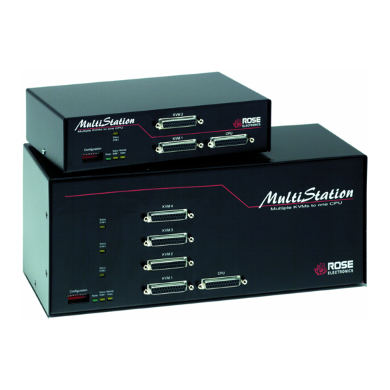
Features Available in three models: ML-2U - standalone unit with 2 KVMs and 1 CPU ML-4U - standalone unit with 4 KVMs and 1 CPU MLK-2U – distributed units have local unit with 1 KVM and 1 CPU and remote unit with 1 KVM up to 250’ apart Fully automatic KVM sharing on first-come first-serve basis Adjustable keyboard timeout on each station Instant keyboard LED synchronization... -
Page 10: Front Panel - Model Ml-2U
PANEL DESCRIPTION Front panel – model ML-2U Dip Switch Remote Video LED Status LEDs Power LED KVM connectors Computer connector Figure 1. ML-2U Front Panel Table 1. Front panel - model ML-2U Enables commands from keyboard at each KVM station. Up is Dip Switch enable, down is disable. -
Page 11: Rear Panel - Model Ml-2U
Rear panel – model ML-2U RS232 Power Power Connector Switch Connector Figure 2. ML-2U Rear Panel Table 2. Rear panel - model ML-2U RS232 RS232 serial port for factory diagnostics only Power Pressing the switch turns the unit on, provided supplied power transformer is properly connected. -
Page 12: Front Panel - Model Ml-4U
Front panel – model ML-4U Remote Video LED Dip Switch Status LEDs Power LED Keyboard-Video- Computer connector Mouse connectors Figure 3. ML-4U Front Panel Table 3. Front panel - model ML-4U Enables commands from keyboard at each KVM station. Up is enable, down is disable. -
Page 13: Rear Panel - Model Ml-4U
Rear panel – model ML-4U RS 232 Power Power Connector switch connector Figure 4. ML-4U Rear Panel Table 4. Rear panel - model ML-4U RS232 RS232 serial port for factory diagnostics only Power Pressing the switch turns the unit on, provided supplied power transformer is properly connected. -
Page 14: Front Panel - Model Mlk-2U
Front panel – model MLK-2U LOCAL UNIT Dip Switch Remote Video LED Status LEDs Power LED Keyboard-Video- Computer connector Mouse connectors REMOTE UNIT Status LEDs Power LED Keyboard-Video-Mouse connectors Figure 5, MLK-2U Front Panel Table 5. Front panels - model MLK-2U Only present on the local unit. -
Page 15: Rear Panel - Model Mlk-2U
Rear panel – model MLK-2U LOCAL UNIT REMOTE UNIT Figure 6. MLK-2U Rear Panel Table 6. Rear panels - model MLK-2U RS232 serial port for factory diagnostics only RS232 Power switch Pressing this switch turns the unit on or off Power Included power transformer connection Bus cable connection for the local and remote unit... -
Page 16: Installation Procedure
INSTALLATION Installation procedure Step 1. Connecting the keyboards, monitors, and mice The Keyboard-Video-Mouse adapter cable connects one keyboard, one video monitor, and one mouse to the MultiStation. Cables will vary depending upon the connector type on your keyboard and whether you are using a PS/2 or serial mouse. -
Page 17: Step 2. Connecting The Computer
Step 2. Connecting the computer A CPU adapter cable connects your computer to the MultiStation. The cable type will vary depending on the computer’s keyboard and mouse connectors. 2.1 Connect the CPU adapter cable’s DB-25M connector to the DB-25F connector labeled CPU on the MultiStation front panel. 2.2 Connect the keyboard, mouse, and monitor connectors on the CPU adapter cable to the corresponding ports on the computer. -
Page 18: Step 3. Connecting The Bus Cable (Model Mlk-2U Only)
Step 3. Connecting the bus cable (model MLK-2U only) Step #3 applies to MultiStation model MLK-2U only. If your model is model ML-2U or ML-4U, skip this step. The bus cable (13W3M / 13W3M) connects between the local MultiStation and the remote unit. 3.1 Connect one end of the bus cable to the local unit’s “BUS OUT”... -
Page 19: Step 4. Powering Up The System
Step 4. Powering up the system 4.1 Connect the provided power adapter(s) to the power connector on the rear panel of MultiStation and to a power strip or wall outlet. Model MLK-2U requires two power adapters, one for the local unit and one for the remote unit. -
Page 20: Dip Switch Settings
OPERATION Dip Switch Settings The front panel dip switch enables or disables commands from each KVM station. To enable commands from a KVM station put the corresponding dip switch in the up position. To disable commands, put the switch in the down position. -
Page 21: Table 8. Keyboard Commands
Keyboard Command Summary Table 8 is a summary of the available keyboard commands. See the detailed descriptions for an expanded explanation of each command. [Ctrl] in the Key Sequence column is a press and release of the right control key followed by the command. -
Page 22: Keyboard Command Detailed Descriptions
Keyboard Command Detailed Descriptions NOTE: Follow all inputs that require entering a numeric value by the KEEP command to save the change. Reset Command (Right Ctrl + R) The reset command is used to reinitialize the mouse and keyboard without cycling power on the MultiStation. -
Page 23: Mode Command (Right Ctrl + M + 1, 2, Or 3 + Enter)
Mode command (Right Ctrl + M + 1, 2, or 3 + Enter) MultiStation automatically detects the computer’s keyboard mode upon computer boot-up. If the computer is already booted and then connected to MultiStation, the computer’s keyboard mode can not be detected and the mode stored in non-volatile memory is used. -
Page 24: Rs232 Mouse Type (Right Ctrl + Q + Value + Enter)
RS232 mouse type (Right Ctrl + Q + value + Enter) This command is used to match your KVM station’s mouse to the mouse type used on the connected computer. The default command value is 0 for auto- detect. If the KVM station’s mouse type is the same as the computer’s mouse this command does not need to be issued (PS/2 to PS/2 or Serial to Serial). -
Page 25: Power Interruption
The table uses a letter, which shows the cable type, and a number that refers to the quality of the video, as described below. Rose Electronics does not recommend systems where the video quality is 1 or 2. There are further capabilities not listed here in order to send the higher resolution video longer distances. -
Page 26: Rackmount Kit
RACKMOUNTING Rackmount kit Rackmount kits are available to mount your MultiStation in a 19”, 23”, or a 24” rack. See appendix C for description and part numbers. The optional rack mount kit includes the following items: Black anodized rack mounting shelf Four mounting screws. -
Page 27: Troubleshooting
TROUBLESHOOTING TroubleShooting The troubleshooting section is used as a guide to understanding the capabilities of the MultiStation and for general troubleshooting. If you have any problems or questions concerning the installation, operation or usage of the MultiStation that is not covered in this manual, please contact Rose Electronics for technical support. - Page 28 e. If you are using model MLK-2U and can not access the computer from the remote unit, check the power on the local unit or the bus cable is disconnected. Check the status LEDs on the local and remote unit. If they are not flashing at 1 second intervals, the bus cable may have a problem.
-
Page 29: Safety
SAFETY Safety The MultiStation has been tested for conformance to safety regulations and requirements, and has been certified for international use. Like all electronic equipment, the MultiStation should be used with care. To protect yourself from possible injury and to minimize the risk of damage to the Unit, read and follow these safety instructions. -
Page 30: Maintenance And Repair
This Unit does not contain any internal user-serviceable parts. In the event a Unit needs repair or maintenance, you must first obtain a Return Authorization (RA) number from Rose Electronics or an authorized repair center. This Return Authorization number must appear on the outside of the shipping container. -
Page 31: Appendix A. General Specifications
APPENDICES Appendix A. General Specifications Dimensions ML-2U/MLK-2U local/remote 8.85”W x 2.10”H x 4.90”D ML-4U 13.1”W x 5.25”H x 4.90”D Weight ML-2U/MLK-2U local/remote 3.0 lbs ML-4U 7.0 lbs Input Power 117 VAC adapter, 230 VAC optional Output Power 17VAC CT, 1.45A Connectors Power DIN5... -
Page 32: Appendix C. Parts And Cables
Bus Cable CAB-SMBxx Coax bus cable 13W3M to 13W3M xx = cable length in feet Note: Serial mouse and AT keyboard cables are available. Contact your Rose Electronics representative for more information. Rack Mount RM-SV1 Black anodized / 19” rack RM-SV1/23 Black anodized / 23”... - Page 33 STANDALONE 2 KVMs to 1 CPU (Model ML-2U) STANDALONE 4 KVMs to 1 CPU (Model ML-4U) DISTRIBUTED 2 KVMs to 1 CPU (Model MLK-2U) MULTISTATION INSTALLATION AND OPERATIONS MANUAL...
- Page 34 NOTES MULTISTATION INSTALLATION AND OPERATIONS MANUAL...
- Page 36 10707 Stancliff Road Phone (281) 933-7673 Houston, Texas 77099 WWW.ROSE.COM...
Need help?
Do you have a question about the MultiStation ML-2U and is the answer not in the manual?
Questions and answers