Table of Contents
Advertisement
Quick Links
Advertisement
Table of Contents

Subscribe to Our Youtube Channel
Related Manuals for Intel Aero


Summary of Contents for Intel Aero
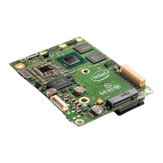
- Page 1 Intel ® Aero Compute Board Hardware Features and Usage Rev 1.5.2...
- Page 2 MAY OCCUR. Intel may make changes to specifications and product descriptions at any time, without notice. Designers must not rely on the absence or characteristics of any features or instructions marked “reserved” or “undefined.” Intel reserves these for future definition and shall have no responsibility whatsoever for conflicts or incompatibilities arising from future changes to them.
-
Page 3: Table Of Contents
Contents Introduction ...................... 5 Intel Aero Compute Board Block Diagram ............6 ® Connector Specifications ..................7 Connector Part Numbers ................7 Connector Locations and Pin Orientation ............ 7 8MP Camera Connector ................8 3.3.1 Connector Pin Definition ............. 8 VGA Camera Connector ................ - Page 4 Intel ® Aero Compute Board inside the Intel ® Aero Ready to Fly Drone (section 6) 1.5.1 February 2018 Corrected reference to chip selects in body of text 3.7.1 to match the block diagram in Figure 1 1.5.2...
-
Page 5: Introduction
Aero Flight Controller are captured in Chapter 6. The Intel ® Aero Flight Controller is assembled as part of the Intel® Aero Ready to Fly Drone. The Flight Controller plugs directly into the Intel ® Aero Compute Board using a dedicated connector. -
Page 6: Intel® Aero Compute Board Block Diagram
Intel® Aero Compute Board Block Diagram Intel ® Aero Compute Board Block Diagram LEGEND Intel® RealSense™ 8MP Camera VGA Camera Intel Component Connector CPU Connection SPI3 Intel®Atom™ FPGA Connection USB3 4 GB DDR3 x7-Z8750 USB2 Flight Controller Connection Processor 4 cores/4 threads... -
Page 7: Connector Specifications
Connector Specifications Connector Specifications Users may connect various devices to the Compute Board by building a custom cable using the connector information provided in Section 3.1 and the pin definitions captured in Chapter 3. Connector Part Numbers Manufacturer Manufacturer Part Mating Connector Connector Name... -
Page 8: 8Mp Camera Connector
MIPI1_DATA3_DP VGA Camera Connector This single-lane CSI-2 (MIPI) interface is intended for connection to the VGA camera with global shutter, included in in the optional Intel ® Aero Vision Accessory Kit. Refer to Figure 2. Connector Locations and Pin Orientation. -
Page 9: Realsense Usb 3.0 Camera Connector
Connector Specifications RealSense USB 3.0 Camera Connector The Intel ® Aero Compute Board has a dedicated connector for the Intel ® RealSense camera (R200) which is included in the optional Intel ® Vision Accessory Kit. This low- profile custom connector interfaces directly to one of the processor’s USB 3.0 ports. -
Page 10: Connector Pin Definition
IO Expansion Connector 3.7.1 Connector Pin Definition The Intel ® Aero Compute Board has a configurable 80-pin IO Expansion Connector. In addition to power and ground pins, this connector provides access to the processor GPIOs and processor HSUART. The on-board Altera ®... -
Page 11: Software Access
Connector Specifications FPGA FPGA Pin Name Pin# Pin# Pin Name Pin # Pin # AERO_RTF_FC_SDIO / FPGA_ADC_1 FGPA_GPIO_26 AERO_RTF_FC_SDIO / FPGA_ADC_2 FGPA_GPIO_27 AERO_RTF_FC_SDIO / FPGA_ADC_3 FGPA_GPIO_28 AERO_RTF_DRONE_VBATS FPGA_GPIO_01 ENSE / FPGA_ADC_4 FPGA_ADC_5 FPGA_GPIO_02 FPGA_GPIO_03 CPU_GPIO_05 FPGA_GPIO_04 CPU_GPIO_06 FPGA_GPIO_05 CPU_GPIO_01 FPGA_GPIO_06 CPU_HSUART0_TX FPGA_GPIO_07 CPU_HSUART0_RX... - Page 12 Processor CAN Bus The Intel ® Aero Compute Board includes a CAN Bus interface (MCP2515 CAN Controller and a MCP2562 CAN Transceiver) that is connected to the Intel ® Atom™ processor’s SPI bus. (see block diagram in Chapter 2). For usage information, refer to the “CAN...
-
Page 13: 80-Pin Accessories Connector Pinout Definition
Connector Specifications 80-pin Accessories Connector Pinout Definition The 80-pin Accessories Connector is a flexible circuit board with five Hirose DF13 connectors that is packaged with the Intel ® Aero Compute Board. This Accessories Connector plugs into the IO Expansion Connector (Section 3.7). Signal routing for each of the five connectors, labeled J1 through J5, is defined in the pin definition tables below. -
Page 14: J2" Radio Control
Connector Specifications 3.8.2 “J2” Radio Control Pin # Pin Name FPGA Pin Name† +3.3V RC_RX FPGA_GPIO_18 † Refer to the IO Expansion Connector pin definition table in Section 3.7. 3.8.3 “J3” GPS Pin # Pin Name FPGA Pin Name† +VBAT GPS_TX FPGA_GPIO_15 GPS_RX... -
Page 15: On-Board Sensors
On-Board Sensors The Intel ® Aero Compute Board is designed with a 6 Degree of Freedom IMU (BMI160), a magnetometer (BMM150), and an altimeter (MS5611). The sensors are connected to the processor SPI bus and I2C bus. Full details how to access each sensor can be found in the article “Onboard... -
Page 16: Led Definition And Usage
Compute Board LEDs The Intel ® Aero Compute Board has a total of 8 LEDs. Four are located on the top side of the board. The other Four LEDs are located on the bottom side. Refer to Figure 9 Figure 10 The table below describes each LED and its function. -
Page 17: Compute Board Top Side Led Locations
LED Definition and Usage Compute Board Top Side LED Locations Figure 9. LEDs on Top Side of Compute Board... -
Page 18: Compute Board Bottom Side Led Locations
LED Definition and Usage Compute Board Bottom Side LED Locations Figure 10. LEDs on Bottom Side of Compute Board... -
Page 19: Intel® Aero Flight Controller
Flight Controller Connection Analog[5], GPIO[24] Altera® MAX®10 Micro-controller Connection GPIO[4] FPGA Connector (TJA1051) 0x0E (HMC5883L) I2C3 0x77 Alt/Pressure (MS5611 or 5607) STM32 MCU (STM32F427VI) SPI1 Gyro/Accel (MPU-6500) Intel® Aero Flight Controller Figure 11. Hardware Block Diagram – Aero Flight Controller...
Need help?
Do you have a question about the Aero and is the answer not in the manual?
Questions and answers