Table of Contents
Advertisement
Quick Links
Advertisement
Table of Contents

Related Manuals for Intel AL440LX


Summary of Contents for Intel AL440LX
- Page 1 AL440LX Motherboard Product Guide Order Number: 680701-001...
-
Page 2: Revision History
First release of the AL440LX Motherboard Product Guide. July 1997 Intel Corporation (Intel) makes no warranty of any kind with regard to this material, including, but not limited to, the implied warranties of merchantability and fitness for a particular purpose. Intel assumes no responsibility for any errors that may appear in this document. -
Page 3: Table Of Contents
Contents 1 Product Description Features..........................7 Components..........................8 Back Panel I/O Connectors....................9 2 Installing the Motherboard Before You Begin........................11 Installing a Processor......................12 Installing the Retention Mechanism................12 Installing the Processor ....................13 Setting the Processor Speed..................14 ® Upgrading to a Boxed Pentium II Processor ..............14 Removing the Installed Processor................15 Removing the Heatsink Support Base................16 Upgrading the Processor....................18... - Page 4 Contents 5 Upgrading the BIOS Preparing for the Upgrade ....................41 Obtaining the Upgrade Utility ..................41 Recording the Current BIOS Settings.................41 Creating a Bootable Floppy Diskette ................42 Creating the BIOS Upgrade Floppy Diskette..............42 Upgrading the BIOS......................42 Recovering the BIOS ......................43 Changing the BIOS Language ....................44 6 Technical Reference Motherboard Connectors ....................45 Front Panel Connectors ......................48...
- Page 5 AL440LX Motherboard Product Guide Figures Motherboard Components....................8 Back Panel I/O Connectors ..................9 Installing the Processor Retention Mechanism ............12 Installing the Processor ....................13 Installing the Heatsink Support Top Bar..............14 Removing the Heatsink Support Top Bar and the Processor ........15 Removing the Heatsink Support Retention Pins ............16 Placing the Heatsink Support Base Removal Tool on the Retention Pins....17...
- Page 6 Contents Front Panel Connectors .....................48 Memory Map ......................49 DMA Channels ......................49 I/O Map ........................50 PCI Configuration Space Map..................52 Interrupts ........................52 Beep Codes .......................53 BIOS Error Messages ....................53...
-
Page 7: Product Description
Intel LANDesk Client Manager, and support for chassis security NOTE Information about Intel motherboards including technical product specifications, BIOS upgrades, and device drivers is available under “Product Info” at the Intel World Wide Web site: http://www.intel.com/... -
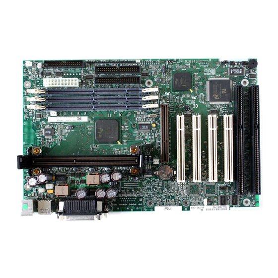
Page 8: Components
Wake on Ring header Slot 1 connector Speaker Fan 3 header (for the active heatsink fan) Fan 2 header DIMM sockets PCI connectors Primary power connector ISA connectors Fan 1 header NOTE Components labeled optional do not come on all AL440LX motherboards. -
Page 9: Back Panel I/O Connectors
AL440LX Motherboard Product Guide Back Panel I/O Connectors Figure 2 shows the back panel connectors on the motherboard. OM06235 Figure 2. Back Panel I/O Connectors † PS/2 connector (mouse or keyboard) Serial port 1 connector Parallel port connector Serial port 2 connector... - Page 10 Product Description...
-
Page 11: Installing The Motherboard
2 Installing the Motherboard This chapter describes the following: • Installing a processor • Preparing the motherboard for installing a boxed Pentium II processor • Installing and removing memory • Replacing the battery • Installing and removing the motherboard Before You Begin CAUTION Before you install this motherboard in a chassis, see Appendix B for regulatory requirements and precautions. -
Page 12: Installing A Processor
3. Set the processor speed. Detailed instructions for each of these procedures follow. NOTE If you are installing a boxed Intel Pentium II processor, see the instructions on page 14. Installing the Retention Mechanism NOTE To install the retention mechanism, you need a Phillips (#2 bit) manual torque screwdriver capable of a 6.0 in.-lb. -
Page 13: Installing The Processor
AL440LX Motherboard Product Guide CAUTION Overtightening the captive nuts on the retention mechanism can damage the motherboard. Tighten the captive nuts (E in Figure 3) to no more than 6.0 in.-lb. ± 1.0 in.-lb. (0.678 N-m ± 0.113 N-m). 4. Finger tighten all four captive nuts to make sure they start correctly on the threads of the attachment studs. -
Page 14: Setting The Processor Speed
Installing the Motherboard 3. Slide the top heatsink support bar (A) onto the retaining pins (B) of the support’s base as shown in Figure 5. OM06229 Figure 5. Installing the Heatsink Support Top Bar Setting the Processor Speed After you install the processor and install the motherboard, set the processor speed by using the Setup program. -
Page 15: Removing The Installed Processor
AL440LX Motherboard Product Guide Removing the Installed Processor To remove the installed processor, follow these steps: 1. Observe the precautions in “Before You Begin” (see page 11). 2. Turn off all peripheral devices connected to the computer. Turn off the computer. -
Page 16: Removing The Heatsink Support Base
Installing the Motherboard Removing the Heatsink Support Base NOTE To remove the heatsink support base from the motherboard, you need a special removal tool (MID #58982) that is available from Dexter Design (call 503-648-7000 for ordering information). To remove the heatsink support base follow these steps: 1. -
Page 17: Placing The Heatsink Support Base Removal Tool On The Retention Pins
AL440LX Motherboard Product Guide 2. Place the heatsink support removal tool (A) over the two outside posts of the heatsink support base (B) as shown in Figure 8. Make sure the tool completely engages the posts. OM06232 Figure 8. Placing the Heatsink Support Base Removal Tool on the Retention Pins... -
Page 18: Upgrading The Processor
(Figure 9). There is an audible click when the base disengages from the motherboard. OM06233 Figure 9. Using the Heatsink Support Base Removal Tool 4. Remove the tool and the heatsink support base from the motherboard. Upgrading the Processor Refer to the boxed Intel Pentium II processor documentation for installation instructions. -
Page 19: Installing Memory
ECC Configuration feature in the Setup program (see page 34). NOTE DIMMs must meet the Intel specifications for either 64-bit or 72-bit SDRAM. For information about vendors that support these specifications refer to the Intel World Wide Web site: http://www.intel.com/ Figure 10 shows the location of the DIMM sockets. -
Page 20: Removing Memory
Installing the Motherboard 6. Position the DIMM above the socket. Align the two small notches in the bottom edge of the DIMM with the keys in the socket. 7. Insert the bottom edge of the DIMM into the socket. 8. When the DIMM is seated, push down on the top edge of the DIMM until the retaining clips at the ends of the socket snap into place. -
Page 21: Replacing The Battery
AL440LX Motherboard Product Guide Replacing the Battery When your computer is turned off, a lithium battery keeps the time-of-day clock and the values in CMOS RAM current. Figure 12 shows the location of the battery. The battery should last about seven years. When the battery begins to die, it loses voltage; when the voltage drops below a certain level, the Setup program settings stored in CMOS RAM (for example, the date and time) might not be accurate. -
Page 22: Replacing The Battery
Installing the Motherboard To replace the battery, follow these steps: 1. Observe the precautions in “Before You Begin” (see page 11). 2. Turn off all peripheral devices connected to the computer. Turn off the computer 3. Remove the computer cover. 4. -
Page 23: Installing And Removing The Motherboard
AL440LX Motherboard Product Guide Installing and Removing the Motherboard Refer to your chassis manual for instructions on installing and removing the motherboard. NOTES You will need a Phillips (#2 bit) screwdriver. Refer to Appendix B for regulatory requirements and installation instructions and precautions. - Page 24 Installing the Motherboard...
-
Page 25: Configuring The Motherboard
3 Configuring the Motherboard This chapter describes how to configure the motherboard using the Setup program. Refer to Chapter 4 for more information about Setup. Before You Begin CAUTION If you are installing this motherboard in a chassis, see Appendix B for regulatory requirements and precautions. -
Page 26: Configuration Modes
Configuring the Motherboard Configuration Modes The Setup program has three configuration modes: • Normal mode for normal operations • Configure mode for configuring the processor speed and clearing passwords • Recovery mode for recovering the BIOS data Figure 14 shows the location of the configuration header on the motherboard. The jumper is usually set to normal mode at the factory. -
Page 27: Setting The Processor Speed
AL440LX Motherboard Product Guide Table 1 shows jumper settings for the different Setup modes. These modes configure Setup for normal operations, maintenance options, or recovering the BIOS. Table 1. Jumper Settings for the Setup Program Jumper Function (J8B2) Description Normal BIOS uses current configuration and passwords for booting. -
Page 28: Clearing The Passwords
Configuring the Motherboard 13. On the header (J8B2), move the jumper back to pins 1-2 to restore normal operation as shown below. J8B2 OM06240A 14. Replace the cover and turn on the computer. 15. Verify the processor speed in the startup information the BIOS displays. Clearing the Passwords This procedure assumes that the motherboard is installed in the computer and the configuration header (J8B2) has the jumper set on pins 1-2 for normal mode. -
Page 29: Using The Setup Program
4 Using the Setup Program This chapter provides an overview of the Setup program. You can use the Setup program to change the configuration information and boot sequence for the computer. NOTE For reference purposes, you should write down the current Setup settings. When you make changes to the settings, update this record. -
Page 30: Function Keys
Using the Setup Program Function Keys Table 3 shows the function keys available for menu screens. Table 3. Setup Function Keys Setup Key Description <F1> or <Alt-H> Brings up a help screen for the current item. <Esc> Exits the menu. <←>... -
Page 31: Main Menu
AL440LX Motherboard Product Guide Main Menu This menu reports processor and memory information. Use it to configure the system date, system time, floppy options, and IDE devices. Table 5. Main Menu Feature Options Description Processor Type No options Displays processor type. -
Page 32: Floppy Options Submenu
Using the Setup Program Floppy Options Submenu Use this submenu to configure floppy drives. Table 6. Floppy Options Submenu Feature Options Description • Diskette A: Specifies the capacity and physical size Disabled • 360 KB, 5¼″ of diskette drive A. •... -
Page 33: Ide Device Configuration Submenus
AL440LX Motherboard Product Guide IDE Device Configuration Submenus Use this submenu to configure IDE devices, including: • Primary IDE master • Primary IDE slave • Secondary IDE master • Secondary IDE slave Table 7. IDE Device Configuration Submenus Feature Options Description •... -
Page 34: Advanced Menu
Using the Setup Program Advanced Menu Use this menu to set advanced features that are available through the chipset. Table 8. Advanced Menu Feature Options Description • Plug & Play O/S Specifies if a Plug and Play operating system is being •... -
Page 35: Resource Configuration Submenu
AL440LX Motherboard Product Guide Resource Configuration Submenu Use this submenu to configure the memory and interrupts. Table 9. Resource Configuration Submenu Feature Options Description • Memory C800 - CBFF Available (default) | Reserved Reserves specific • Reservation upper memory blocks... -
Page 36: Peripheral Configuration Submenu
Using the Setup Program Peripheral Configuration Submenu Use this submenu to configure the computer peripherals. Table 10. Peripheral Configuration Submenu Feature Options Description • Serial port A Configures serial port A. Disabled • Enabled Auto assigns the first free COM port, normally COM1, •... -
Page 37: Keyboard Features Submenu
AL440LX Motherboard Product Guide Keyboard Features Submenu Use this submenu to set keyboard features. Table 11. Keyboard Features Submenu Feature Options Description • Numlock Specifies the power on state of the Numlock Auto (default) • feature on the numeric keypad of the keyboard. -
Page 38: Security Menu
Using the Setup Program Security Menu Use this menu to set passwords and security features. Table 14. Security Menu Feature Options Description User Password Is No options Reports if there is a user password set. Supervisor Password Is No options Reports if there is a supervisor password set. -
Page 39: Boot Menu
AL440LX Motherboard Product Guide Boot Menu Use this menu to specify the boot features and the boot sequence. Table 16. Boot Menu Feature Options Description • Restore on Stay Off Specifies how the computer responds following a power • AC/Power Loss failure. -
Page 40: Hard Drive Submenu
Using the Setup Program Hard Drive Submenu Use this submenu to configure the boot sequence for hard drives. Table 17. Hard Drive Submenu Options Description • Specifies the boot sequence for the hard drives attached to the computer. To Installed hard drive •... -
Page 41: Upgrading The Bios
You can upgrade to a new version of the BIOS using the new BIOS files and the BIOS upgrade utility, iFLASH.EXE. You can obtain the BIOS upgrade file and the iFLASH.EXE utility through your computer supplier or from the Intel World Wide Web site: http://www.intel.com. -
Page 42: Creating A Bootable Floppy Diskette
Upgrading the BIOS Creating a Bootable Floppy Diskette † 1. Use a DOS or Windows 95 system to create the floppy disk. 2. Insert a floppy disk in floppy drive A. 3. At the C:\ prompt, for an unformatted floppy disk, type: format a:/s or, for a formatted floppy disk, type: sys a:... -
Page 43: Recovering The Bios
AL440LX Motherboard Product Guide 8. To enter the Setup program, press when you see the message: <F2> Press <F2> Key if you want to run SETUP 9. For proper operation, load the Setup program defaults. To load the defaults, press <F9>... -
Page 44: Changing The Bios Language
Changing the BIOS Language You can use the BIOS upgrade utility to change the language the BIOS uses for messages and the Setup program. Use a bootable floppy disk containing the Intel flash utility and language files (see page 42). -
Page 45: Technical Reference
6 Technical Reference Motherboard Connectors The following figure shows the location of the motherboard connectors. Telephony J2F1 Wake on CD-ROM Audio J1C1 Line In Audio J1F1 J2F2 Chassis Security J2B1 Slot 1 J4J1 Fan 2 J3F1 Fan 3 (Active Heatsink Wake on Ring J8A1 Fan) -
Page 46: Wake On Lan Header (J1C1)
Technical Reference Table 21. Wake on LAN Header (J1C1) Signal Name +5 VSB Ground Table 22. ATAPI CD Audio Connector (J1F1) Signal Name CD_IN-Left Ground Ground CD_IN-Right Table 23. ATAPI Telephony Connector (J2F1) Signal Name Audio Out (monaural) Ground Ground Audio In (monaural) Table 24. -
Page 47: Fan 2 Header (J3F1)
AL440LX Motherboard Product Guide Table 26. Fan 2 Header (J3F1) Signal Name Ground FAN_CTRL (+12 V) FAN_SEN* * If the optional management extension hardware is not available, pin 3 is ground. Table 27. Fan 3 Header (J5L1) (Active Heatsink Fan) -
Page 48: Front Panel Connectors
Technical Reference Front Panel Connectors The motherboard has connectors for controls and indicators typically located on the front panel of the computer. J9D1 OM05705 Table 30. Front Panel Connectors Connector Pin Signal Name A. Speaker* SPKR_HDR PIEZO_IN Ground B. Reset switch SW_RST Ground C. -
Page 49: Motherboard Resources
AL440LX Motherboard Product Guide Motherboard Resources Memory Map Table 31. Memory Map Address Range (decimal) Address Range (hex) Size Description 1024 K - 393216 K 100000 - 18000000 383 MB Extended memory 1008 K - 1024 K FC000 - FFFFF... -
Page 50: I/O Map
Technical Reference I/O Map Table 33. I/O Map Address (hex) Size Description 0000 - 000F 16 bytes PIIX4- DMA 1 0020 - 0021 2 bytes PIIX4 - interrupt controller 1 002E - 002F 2 bytes Super I/O controller configuration registers 0040 - 0043 4 bytes PIIX4 - Counter/Timer 1... - Page 51 AL440LX Motherboard Product Guide Table 33. I/O Map (continued) Address (hex) Size Description 0378 - 037F 8 bytes LPT1 0388- 038D 6 bytes AdLib (FM synthesizer) † 03B4 - 03B5 2 bytes Video (VGA 03BA 1 byte Video (VGA) 03C0 - 03CA...
-
Page 52: Pci Configuration Space Map
Description Intel 82440LX (PAC) Intel 82371AB (PIIX4 ) A.G.P. bus Intel 82371AB (PIIX4 ) PCI/ISA bridge Intel 82371AB (PIIX4 ) IDE bus master Intel 82371AB (PIIX4 ) USB Intel 82371AB (PIIX4 ) power management PCI expansion slot 1 (J4D2) PCI expansion slot 2 (J4D1) -
Page 53: A Error Messages
A Error Messages BIOS Beep Codes One long beep followed by several short beeps indicates a video problem. Table 36. Beep Codes Beeps 80h Code Description One short beep before boot Search for option ROMs 1-2-2-3 BIOS ROM checksum 1-3-1-1 Test DRAM refresh 1-3-1-3 Test keyboard controller... - Page 54 Error Messages Table 37. BIOS Error Messages (continued) Error Message Explanation Invalid NVRAM media type Problem with NVRAM (CMOS) access. Keyboard controller error The keyboard controller failed test. Try replacing the keyboard. Keyboard error Keyboard not working. Keyboard error nn BIOS discovered a stuck key and displays the scan code nn for the stuck key.
-
Page 55: B Regulatory And Integration Information
B Regulatory and Integration Information This appendix contains: • Safety standards, electromagnetic compatibility regulations, and product certification markings for this motherboard • Instructions and precautions for integrators who are installing this motherboard in a chassis Regulatory Requirements This printed circuit assembly meets the following safety and electromagnetic compatibility (EMC) regulations when correctly installed in a compatible host computer. -
Page 56: Electromagnetic Compatibility (Emc) Regulations
Regulatory and Integration Information Electromagnetic Compatibility (EMC) Regulations CISPR 22, 2nd Edition, 1993 Limits and methods of measurement of Radio Interference Characteristics of Information Technology Equipment. (International) EN 55 022, 1995 Limits and methods of measurement of Radio Interference Characteristics of Information Technology Equipment. -
Page 57: Installation Precautions
AL440LX Motherboard Product Guide Installation Precautions When you install and test the motherboard, observe all warnings and cautions in the installation instructions. To avoid injury, be careful of: • Sharp pins on connectors • Sharp pins on printed circuit assemblies •... -
Page 58: Ensure Electromagnetic Compatibility (Emc)
Appropriate protection is provided by a maximum 8-Amp current limiting circuit or a maximum 5- Amp fuse or positive temperature coefficient (PTC) resistor. All Intel motherboards now have PTCs on all external ports that provide DC power externally. -
Page 59: Prevent Power Supply Overload
AL440LX Motherboard Product Guide Prevent Power Supply Overload Unless the power supply has inherent overcurrent protection, do not overload the power supply output. To avoid overloading the power supply, make sure that the calculated total current load of all the modules within the computer is less than the output current rating of the power supply. If you do not do this, the power supply could overheat, catch fire, or damage the insulation that separates hazardous AC line circuitry from low-voltage user accessible circuitry. - Page 60 Regulatory and Integration Information...
Need help?
Do you have a question about the AL440LX and is the answer not in the manual?
Questions and answers