Table of Contents
Advertisement
Quick Links
Advertisement
Table of Contents

Subscribe to Our Youtube Channel
Related Manuals for Novus NVC-DN6118SD/IR


Summary of Contents for Novus NVC-DN6118SD/IR
- Page 1 U s e r ’s m a n u a l NVC-DN6118SD/IR...
- Page 2 NVC-DN6118SD/IR User’s manual, ver. 1.0 INFORMATION EMC (2004/108/EC) and LVD (2006/95/EC ) Directives CE Marking Our products are manufactured to comply with requirements of following directives and national regulations implementing the directives: Electromagnetic compatibility EMC 2004/108/EC. Low voltage LVD 2006/95/EC with further amendment. The Directive applies to electrical equipment designed for use with a voltage rating of between 50VAC and 1000VAC as well as 75VDC and 1500VDC.
-
Page 3: Important Safeguards And Warnings
NVC-DN6118SD/IR User’s manual, ver. 1.0 IMPORTANT SAFEGUARDS AND WARNINGS OSTRZEŻENIA ATTENTION! PRIOR TO UNDERTAKING ANY ACTION THAT IS NOT PROVISIONED FOR THE GIVEN PRODUCT IN ITS USER’S MANUAL AND OTHER DOCUMENTS DELIVERED WITH THE PRODUCT, OR THAT ARISES FROM THE NORMAL APPLICATION OF THE... - Page 4 NVC-DN6118SD/IR User’s manual, ver. 1.0 IMPORTANT SAFEGUARDS AND WARNINGS OSTRZEŻENIA 12.To avoid equipment damage, whole TV circuit should be equipped with properly made (in accordance with Polish Regulations) discharge-, overload- and lightning protection devices. Usage of separating transformers is advised.
-
Page 5: Foreword Information
12VDC If any of the listed equipment has been damaged during transport or if the package is incomplete, the contents of package should be packed back to the original box. Contact the local NOVUS distributor for further assistance. MAIN CHARACTERISTICS ... -
Page 6: Technical Specification
NVC-DN6118SD/IR User’s manual, ver. 1.0 TECHNICAL SPECIFICATION TECHNICAL SPECIFICATION NVC-DN6118SD/IR IMAGE Pick-up element CCD imager, 1/3” SONY EXview HAD II Number of Effective Pixels 960 (H) x 582 (V) Horizontal Resolution 650 TVL - color mode, 650 TVL - B/W mode Min. - Page 7 NVC-DN6118SD/IR User’s manual, ver. 1.0 TECHNICAL SPECIFICATION 3.1. Camera dimensions All dimenstions in mm. All rights reserved © AAT Holding sp. z o.o.
-
Page 8: Mounting The Camera
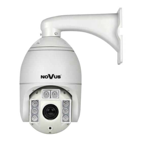
NVC-DN6118SD/IR User’s manual, ver. 1.0 MOUNTING THE CAMERA 3.2. View of the camera, layout of the camera items Wall mount bracket Camera module IR Illuminator Light sensor 4. MOUNTING THE CAMERA In order to obtain declared watertightness camera should be mounted on flat, smooth surfaces. - Page 9 NVC-DN6118SD/IR User’s manual, ver. 1.0 START-UP AND INITIAL CONFIGURATION Tight three screws (4) holding the camera module and bracket. Please make sure the cable goes throughout the passage (5), and screw the bracket to the wall. All conections of power supply and video cables should be done in junction box.
-
Page 10: Ptz Controller
RS485+ and RS485– connectors. Wire color Description Orange RS485+ Yellow RS485- Yellow/green Yellow/green CONTROLLER When conecting telemetry cables into a star a serial data distributor should be used, e.g. NOVUS NVRS-016DD. All rights reserved © AAT Holding sp. z o.o. - Page 11 NVC-DN6118SD/IR User’s manual, ver. 1.0 START-UP AND INITIAL CONFIGURATION 5.3. Camera DIP switch settings Camera features DIP-switch blocks for configuring addresses and transmission parameters for RS-485 protocol. Switches are located under the cover located underneath camera module. Camera address Protocol and speed settings ...
- Page 12 NVC-DN6118SD/IR User’s manual, ver. 1.0 START-UP AND INITIAL CONFIGURATION Except the hardware address (sets by DIP switch), camera allows to set software address. Additional descritpion is in chapter 7.4 Menu System, Address function. Selecting protocol parameters Switches 1 and 2 are related with protocol selection. Table below depicts available switch...
-
Page 13: Controlling The Camera
NVC-DN6118SD/IR User’s manual, ver. 1.0 CONTROLLING THE CAMERA CONTROLLING THE CAMERA N-Control is the recommended control protocol for the Novus PTZ cameras and allows to fully utilise their abilities. Cameras may be also PELCO-D/PELCO-P controlled, however methods of programming and control differ. - Page 14 NVC-DN6118SD/IR User’s manual, ver. 1.0 CONTROLLING THE CAMERA Functions of particular buttons for NV-KBD50 and NVKBD70 are presented below: Manual NV-KDB70 NV-KBD50 Function description iris control - opening, password entering, IRIS OPEN start of programming IRIS CLOSE iris control - closing, end of programming...
- Page 15 NVC-DN6118SD/IR User’s manual, ver. 1.0 CONTROLLING THE CAMERA Using two buttons listed below is necessary in order to program surveillance functions. Please select appropriate number and, holding mentioned button, press the second one (e.g. hold [CTRL] and press [TOUR] )
- Page 16 NVC-DN6118SD/IR User’s manual, ver. 1.0 CONTROLLING THE CAMERA 6.2. Controlling the camera via PELCO-D / PELCO-P protocols Controlling the camera via PELCO-D/PELCO-P protocols is also possible, however methods of programming differ. Furthermore PELCO doesn’t support all camera functions in contrast to N-CONTROL.
- Page 17 NVC-DN6118SD/IR User’s manual, ver. 1.0 CONTROLLING THE CAMERA Functions for the NOVUS NV-KBD50 and NVKBD70 are presented in the table below: Oznaczenie Klawiatura Klawiatura Funkcja w instrukcji NV-KDB70 NV-KBD50 iris control - opening IRIS OPEN iris control - closing IRIS CLOSE...
-
Page 18: Camera Osd Menu
NVC-DN6118SD/IR User’s manual, ver. 1.0 CAMERA OSD MENU 7. CAMERA OSD MENU Before programming or operating the PTZ camera, you have to select a desired camera number (via keyboard or another remote controller). Accessing the camera’s menu depends on the controller type and the protocol used. - Page 19 NVC-DN6118SD/IR User’s manual, ver. 1.0 CAMERA OSD MENU Character will be saved. CLOSE saving the name and get back to the menu. _ A _ _ _ _ _ _ _ _ _ Press CLOSE to Exit 7.1. PTZ FUNCTIONS menu This menu contain settings related with PTZ functions of the camera.
- Page 20 NVC-DN6118SD/IR User’s manual, ver. 1.0 CAMERA OSD MENU 7.1.2. PATTERN submenu Pattern is a sequence of an existing functions (pan, turn, zoom, etc.), that may be called via keyboard or used in tours. Camera allows for saving 6 patterns. Maximum length is 2 minutes per pattern.
- Page 21 NVC-DN6118SD/IR User’s manual, ver. 1.0 CAMERA OSD MENU NUMBER - selects the tour number for editing or run. PROGRAM - enter the programing submenu. It displays screen as below. Using the joystick set the desired field and change its value by pressing OPEN on the keyboard.
- Page 22 NVC-DN6118SD/IR User’s manual, ver. 1.0 CAMERA OSD MENU 7.1.4. SCAN submenu Menu allows to set up scan zones, i.e. two points that the camera shuttles between using the shortest possible track.. Scan 1 Start Point 2 End Point 3 Speed...
- Page 23 NVC-DN6118SD/IR User’s manual, ver. 1.0 CAMERA OSD MENU 7.1.6. HOME FUNCTION submenu Allows to enable a function (preset, pattern or tour) after a pre-defined time of user’s inactivity. Home Function 1 Function 2 Number 3 Delay 4 Operation ON/OFF Press CLOSE to Exit FUNCTION - allows to choose PTZ function beetween: P - Preset, T - Pattern, V - Tour.
- Page 24 NVC-DN6118SD/IR User’s manual, ver. 1.0 CAMERA OSD MENU CAMERA OSD MENU KAMERY TILT END POS - Horizontal coordinate of the opposite corner. NAME - allows to create the particular name for each area. NAME DISPLAY - turn on/off the name displaying on the screen.
- Page 25 NVC-DN6118SD/IR User’s manual, ver. 1.0 CAMERA OSD MENU 7.3. CONTROL SETTINGS menu Menu contains settings of camera module. Control Settings 1 Pan and Tilt 3 Speed Limit ON/OFF 4 Auto Flip ON/OFF. 5 Auto Focus PTZ/OFF/Z 6 Auto AE PTZ/OFF/Z 7 Tour AF ON/OFF.
- Page 26 NVC-DN6118SD/IR User’s manual, ver. 1.0 CAMERA OSD MENU 7.4. CAMERA SETTINGS menu Menu contains camera and exposure settings. Camera Settings 1 Day Night Mode Auto/BW/Color 2 IR Mode Auto/ON/OFF 2 Backlight ON/OFF 3 White Balance Auto/Man/In/Out/ATW 4 R Gain Auto...
- Page 27 NVC-DN6118SD/IR User’s manual, ver. 1.0 CAMERA OSD MENU 7.5. SYSTEM menu Menu contains system options, restoring defaults and address settings. System 1 Clear Memory 2 Restore Default 3 Color Setting PAL/NTSC 4 Information 5 Soft / Hard ID Setting Press CLOSE to Exit CLEAR MEMORY - running this function clears all PTZ functions, reset the camera and PTZ position.
- Page 28 NVC-DN6118SD/IR User’s manual, ver. 1.0 CAMERA OSD MENU CAMERA OSD MENU KAMERY Input Soft ID - allows to set the desired software address for data transmission. Input S/N - require the camera serial number. Enter correct serial number is necessary for setting software ID address.
Need help?
Do you have a question about the NVC-DN6118SD/IR and is the answer not in the manual?
Questions and answers