
Subscribe to Our Youtube Channel
Related Manuals for Ametek T-620


Summary of Contents for Ametek T-620
- Page 1 User Manual Pressure Calibration System C and Hydraulic Pressure Pump Models T-620/T-620H Copyright 2008 AMETEK Denmark A/S...
- Page 2 About this manual…. • The structure of the manual This user manual is aimed at users who are familiar with JOFRA Pressure Calibration Systems, as well as those who are not. The manual is divided into 9 chapters, which describe how to set up, operate, service and maintain the pressure calibration system.
-
Page 3: Table Of Contents
Identifying your JOFRA Pressure Calibration System ..8 3.1 Model description................8 3.2 Receipt of the JOFRA Pressure Calibration System C ....8 Operating instructions............10 4.1 Operating the T-620/T-620H pump..........12 4.2 Media’s to be used..............14 Errors..................15 Returning the JOFRA Pressure Calibration System for service ..................18... -
Page 4: Introduction
• Hand pump, models T-620, T-620H Available instruments * : DPC-500 APM-S/H (* See separate manuals for the instruments) ISO-9001 certified AMETEK Denmark A/S was awarded the ISO-9001 certificate in September 1994 by - Bureau Veritas Certification Denmark. 18-06-2008 126682... - Page 5 Technical assistance Please contact the dealer from whom you acquired the pressure system if you require technical assistance. Guarantee According to current terms of sale and delivery. This guarantee only covers defects in manufacture and becomes void if the Pressure Calibration System has been subject to unauthorised intervention and/or misuse.
-
Page 6: Safety Instructions
Safety instructions Read this manual carefully before using the system! Please follow the instructions and procedures described in this manual. They are designed so that you get the most out of your pressure system and avoid any personal injuries and/or damage to the system. Warning……... - Page 7 Note… The product liability only applies if the pressure system is subject to a manufacturing defect. This liability becomes void if the user fails to follow the maintenance instructions set out in this manual or uses unauthorised spare parts. 126682 00 18-06-2008...
-
Page 8: Identifying Your Jofra Pressure Calibration System
The pumps are compatible with petroleum-based oils or hydraulic fluids. The T-620 pump generates up to 200 bar (3,000 psi) and the T-620H pump generates up to 350 bar (5,000 psi). All pumps feature a 0.5 pint/200 cl built-in oil reservoir, vent valve and vernier valve for fine adjustment. - Page 9 You should receive: • 1 pump T-620/T-620H • 1 hose 20“/0.5m with ¼“ BSP and NPT female connector • 1 roll of teflon tape • 1 aluminium carrying case • 1 calibration certificate • 1 user manual for pump system...
-
Page 10: Operating Instructions
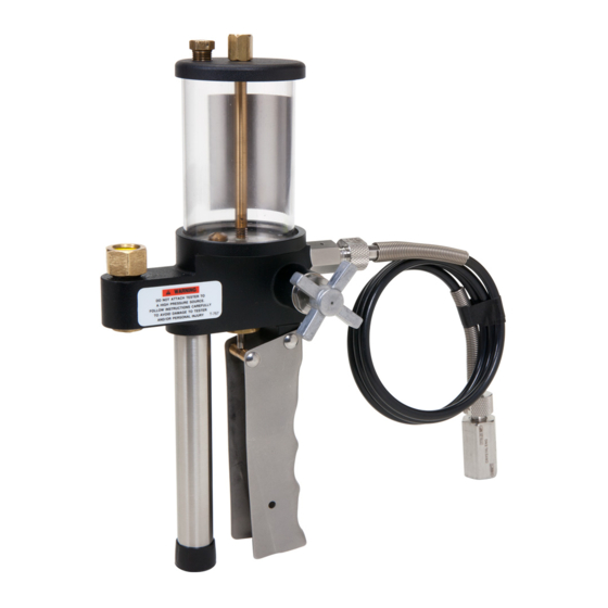
Operating instructions Warning…… About the handling: • Avoid knocking, bumping or dropping the pressure system. This can cause permanent damage to the system and loss of accuracy. About the use: • Do not attach the pump to a high pressure source. Please notice that the pump comes in 2 different pressure ranges. - Page 11 1/4" BSP female 1/4" NPT male 1/4" NPT female 1/4" NPT female Fig 1 DESCRIPTION Fill plug End plug Fitting ¼” NPT male til ¼” BSP female Needle valve Moveable handle Vernier valve Pressure port Pressure port 126682 00 18-06-2008...
-
Page 12: Operating The T-620/T-620H Pump
Operating the T-620/T-620H pump. Warning Do not attach the pump to a high pressure source. Follow these instructions carefully to avoid damage to the pump and/or personal injuries. This routine must be followed in order to operate the system correctly (see fig. - Page 13 The hose may be pre-filled with test fluid on the initial start up to help speed the operation of the pump. Tighten firmly the thread connection of the hose end and device to be tested. Switch the indicator on (for operation see separate manual). Continue to pump the movable handle until the air bubbling in the reservoir stops.
-
Page 14: Media's To Be Used
Media’s to be used Recommended test fluids to be used are : • Petroleum based oils • Hydraulic fluids The fluids are compatible with the aluminium, brass, stainless steel, Teflon, Lexan and Buna N wetted pump parts. Other fluids Contact your local distributor if you want to use other fluids than those stated above. -
Page 15: Errors
• non-original parts are used in any way when operating the system. AMETEK Denmark’s liability is restricted to errors, which originated from the factory. The questions and answers in the following schedule are based on the use of an indicator with a pump system. - Page 16 A pressure increase o The system is in can still not be need of service. obtained. Please contact your local distributor or AMETEK Denmark A/S for advice. 18-06-2008 126682...
- Page 17 Note… Always readjust the pressure after 5 – 10 minutes to allow time for settling of above effects. When you operate with high pressure the sensitivity of the system is high with regard to temperature and movements. 126682 00 18-06-2008...
-
Page 18: Returning The Jofra Pressure Calibration System For Service
Returning the JOFRA Pressure Calibration System for service When in need of service please contact your local distributor for advice or return the system to the manufacturer. For all pressure systems, the pump and the indicator are separate systems. Therefore, a replacement of the pump does not mean that the complete system has to be sent in for repair. - Page 19 ___________________________________________________________________ Safety precautions: if the product has been exposed to any hazardous substances, it must be thoroughly decontaminated before it is returned to AMETEK Denmark A/S. Details of the hazardous substances and any precautions to be taken must be enclosed.
-
Page 20: Maintenance
Maintenance Cleaning Users should/must carry out the following cleaning procedures as and when required: • The exterior of the instrument - Clean using water and a soft cloth. The cloth should be wrung out hard to avoid any water penetrating the calibrator and causing damage. The instrument may also be cleaned using isopropyl alcohol when heavily soiled. -
Page 21: Technical Specifications
Technical specifications Functional specifications (pumps only) Operating Pressure range : • T-620 0 to 200 bar / 0 to 3,000 psi • T-620H 0 to 350 bar / 0 to 5,000 psi, Wetted parts Aluminium, brass, stainless steel, Lexan “O”-rings... - Page 22 With IPI indicator : Weight 5.5 kg. / 12.13 lbs Size 188 x 350 x 560 mm / 7.4 x 13.8 x 22 inch 18-06-2008 126682...
-
Page 23: List Of Accessories And Spare Parts
T-620H Hand pump: 0 to 350 bar / 5.000 psi Handpump are delivered without oil MGAAA/QT Oil for T-620 & T-1 pump AAA OIL in 1-QUART CAN MGAAA/GL Oil for T-620 & T-1 pump AAA OIL in 1-GALLON CAN 126086... -
Page 24: Exploded View - System C With Dpc-500 Calibrator
9.1.1 Exploded view – System C with DPC-500 calibrator 18-06-2008 126682... -
Page 25: System C With Apc Calibrator
T-620H Hand pump: 0 to 350 bar / 5.000 psi Handpump are delivered without oil MGAAA/QT Oil for T-620 & T-1 pump AAA OIL in 1-QUART CAN MGAAA/GL Oil for T-620 & T-1 pump AAA OIL in 1-GALLON CAN 123958... - Page 26 System C with APC calibrator - continued Item Parts No. Description 124717 1 x 9 Volt rechargeable battery 124718 Charger for rechargeable batteries - 115/230 VAC 18-06-2008 126682...
-
Page 27: Exploded View - System C With Apc Calibrator
65P175 / 65P180 1/4" BSP male 60R120 1/4" BSP female T-786 1/4" NPT male 1/4" NPT female T-649 Torque Maximum torque allowed is 13,5 Nm = 10 ftlbs. NEVER exceed the torque allowed. 1/8" NPT male T-620/ T-620H T-878 126682 00 18-06-2008... -
Page 28: System C With Ipi Indicator
T-620H Hand pump: 0 to 350 bar / 5.000 psi Handpump are delivered without oil MGAAA/QT Oil for T-620 & T-1 pump AAA OIL in 1-QUART CAN MGAAA/GL Oil for T-620 & T-1 pump AAA OIL in 1-GALLON CAN 123958... -
Page 29: Exploded View - System C With Ipi Indicator
65P175 / 65P180 1/4" BSP male 60R120 1/4" BSP female T-786 1/4" NPT male 1/4" NPT female T-649 Torque Maximum torque allowed is 13,5 Nm = 10 ftlbs. NEVER exceed the 1/8" NPT male torque allowed. T-620/ T-620H 126682 00 18-06-2008... -
Page 30: System C With Apm-S Pressure Module
T-620H Hand pump: 0 to 350 bar / 5.000 psi Handpump are delivered without oil MGAAA/QT Oil for T-620 & T-1 pump AAA OIL in 1-QUART CAN MGAAA/GL Oil for T-620 & T-1 pump AAA OIL in 1-GALLON CAN T-649... -
Page 31: Exploded View - System C With Apm-S Pres. Module
9.4.1 Exploded view – System C with APM-S pressure module 1/4" BSP female 65P175 / 65P180 1/4" BSP male 60R120 APM-S 1/4" BSP female T-786 1/4" NPT male 1/4" NPT female T-649 11-90057 1/8" NPT male T-620/ T-620H 126682 00 18-06-2008... -
Page 32: System C With Apm-H Pressure Module
T-620H Hand pump: 0 to 350 bar / 5.000 psi Handpump are delivered without oil MGAAA/QT Oil for T-620 & T-1 pump AAA OIL in 1-QUART CAN MGAAA/GL Oil for T-620 & T-1 pump AAA OIL in 1-GALLON CAN T-649... -
Page 33: Exploded View - System C With Apm-H Pres. Module
1/4" BSP female 65P175 / 65P180 APM-H 1/4" BSP male 60R120 1/4" BSP female T-786 1/4" NPT male 1/4" NPT female 7/16" - 20 SAE/MS male - T-649 1/8" NPT female 11-90067 1/8" NPT male T-620/ T-620H 126682 00 18-06-2008...
Need help?
Do you have a question about the T-620 and is the answer not in the manual?
Questions and answers