Advertisement
Overview
„INTRODUCTION
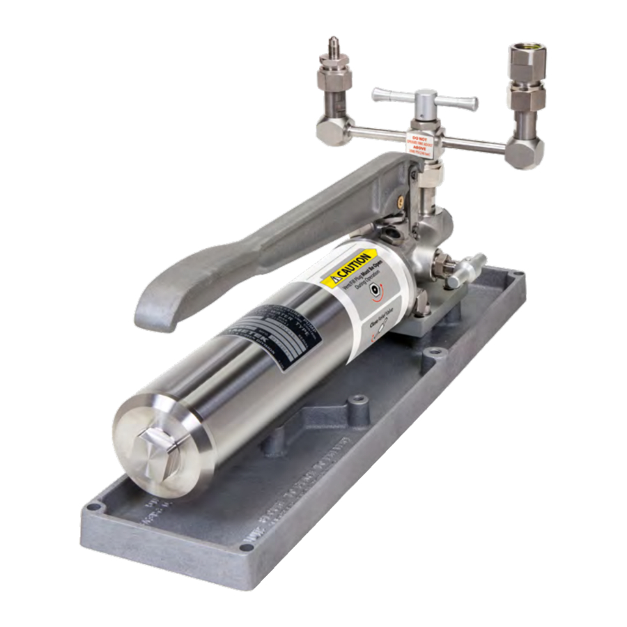
The Type T Series hand pump, mounted on a drip pan with a manifold assembly, is capable of producing pressures up to 1000 bar/15 000 psi.
These units are self-contained pressure sources designed to test instruments. They may be used to calibrate pressure gauges or to set hydraulic relief valves and pressure switches. These units produce pressure to test components or systems, and work independently of other pressure sources. CPFŠ versions include Crystal Pressure Fittings (CPF), which allow users to produce leak-free seals without tools or thread tape. CPF fittings also include a self-venting weep hole to help assure a safe disconnection from a pressurized system. T, T-1, and T-2 pumps1 may be ordered as part of a Pump System, complete with a JOFRA or Crystal Pressure Indicator. T-3 pumps ship as part of a complete comparator testing kit, including four analog test gauges and necessary mounting tools and fittings, all housed in a rugged metal carrying case. For more details on T-3 comparator testing kits, refer to T-3 Pumps for Hydraulic Comparator Kits.
All Type T Series Pump Systems include the most commonly used pressure fittings, seals, etc., all packaged in a carrying case with a custom insert.
1 T designates a pump only. T-1 designates a pump with a manifold and tools. T-2 designates a pump with manifold, tools, and a carrying case.
T, T-1, and T-2 Pumps

| Pressure Medium | O-rings | Pump System | |
| T-1 | Water * | Buna-N | FWB |
| T-1-CPF | Oil or Water * | Viton® | FOV or FWV |
| T-1/VITON | Water * | Viton® | FWV |
| T-1/EPT | Water * | EPT | FWE |
| T-1/OIL | Oil | Buna-N | FOB |
| T-1/OIL/VITON | Oil | Viton® | FOV |
| T-1/OIL/EPT | Oil | EPT | FOE |
* Water is a 50/50 mixture of water and Isopropyl Alcohol.

„FEATURES AND PARTS LISTS
Type T Series hand pumps may be ordered with either oil or a water/alcohol mixture as the pressure medium. There are three available seal packages for the system: Buna-N, Viton®, and EPT.
All Type T Series hand pumps feature a vent valve, and dual volume control for rapid pressure increase at lower pressures and easier pumping at higher pressures. T-1, T-2, and T-3 models include a dual pressure port manifold with fine adjust, plus replacement o-rings and a set of service tools. Refer to Figure 3 for more details on the included tools.


* For more details refer to T-3 Pumps for Hydraulic Comparator Kits and to Figure 4.
Parts Included with Pump Systems for Crystal Reference Indicators

Hydraulic Fluid
Type T Series Pump Systems are only available delivered empty. You will still need to specify what fluid type you are going to use (for example; FOV for Oil or FWV for Water).

Ordering a Pump System
Any Type T Series Pump System may be ordered with or without a reference indicator. The table below provides an explanation of the Pump System ordering scheme when ordering a system without an indicator. For details on ordering the Pump Systems with an indicator, see the indicator datasheet.

X SAMPLE PART NUMBERS
NV-NONE-FOV-E System F pump system (for nVision) drained of fluid, for use with oil.
IS30-NONE-FWV-E System F pump system (for 30 Series) drained of fluid, for use with water.
15KPSIXP2i-FWV-E System F pump system, drained, for use with water, with a 15 000 psi XP2i gauge included.
Safety Instructions
„WARNINGS, CAUTIONS, AND NOTES

- Do not connect any external pressure source to this instrument. This unit is designed to test pressure measuring devices connected to the manifold only. Pressure from an external source can result in explosion of the liquid reservoir and possible bodily injury.
- This pump produces pressure up to 15 000 psi. The pressure rating of tubing and fittings used to connect the pump to the test device should exceed 15 000 psi.
- Do not operate above 15 000 psi/1000 bar.

- To prevent the reservoir from overflowing upon venting, the volume of oil pumped should never exceed the reservoir volume.
- Never operate the pump without fluid in the reservoir. The piston and o-rings require lubrication.
- Do not operate the fine adjust knob above 3500 psi.
- The vent plug must be open to operate this instrument.
 Notes: All wetted parts are stainless steel, Monel, or Buna-N. Optional o-ring materials are Viton and EPT.
Setup
ASSEMBLY
- Open the vent valve.
![]()
- Attach the pressure manifold to the pump body.
![]()
- Close the vent valve.


Note: If using the T-1-CPF, fill with test fluid through the gauge connections. This may take approximately 15 minutes.
Note: It may be necessary to prime the pump, particularly for first time use, or if the pump has been inactive for an extended period of time. Refer to Priming for instructions on priming the pump.
- Pull the pump handle to the top of its stroke.
- Pull out the valve rod selector to select the low pressure/high volume setting.
![]()
- Gently operate the pump handle until test fluid fills the top of the pressure ports on the pressure manifold.
![information]() Note: Lightly tap the manifold to make sure that any air bubbles sticking to the walls or in low flow areas are released to float to the surface.
Note: Lightly tap the manifold to make sure that any air bubbles sticking to the walls or in low flow areas are released to float to the surface. - Attach the reference instrument and the device under test to the manifold.
![information]() Note: If CPF Fittings are used in your pressure system, remaining air can be purged by applying 10 psi or less and loosening the CPF fitting closest to the pressure device. When fluid and air escape from the CPF weep hole, that portion of the system is purged. Repeat this process for each pressure device in the pressure system which is connected to a CPF fitting.
Note: If CPF Fittings are used in your pressure system, remaining air can be purged by applying 10 psi or less and loosening the CPF fitting closest to the pressure device. When fluid and air escape from the CPF weep hole, that portion of the system is purged. Repeat this process for each pressure device in the pressure system which is connected to a CPF fitting.
![]()
Always choose a reference instrument with a range equal to or greater than the range of the device under test. - Ensure all connections are tight and leak free.

Operation and Maintenance
„GENERATING PRESSURE
Note: It may be necessary to prime the pump, particularly if the pump has been inactive for an extended period of time. Refer to Priming for instructions on priming the pump.
- Check that the vent fill plug is fully open by turning it counter-clockwise.
- Open the vent valve.
- Set the valve rod selector to control your desired fluid output volume.
![]()

Only move the valve rod selector while the pump handle is stationary, in the up position.
Note: With the valve rod in the "out" position, fluid flow will be at maximum and the maximum achievable pressure will be 1000 psi. To exceed 1000 psi, push the valve rod in.
- Zero the reference indicator and the device under test.
- Close the vent valve.
- Operate the pump handle to achieve a system pressure close to, but less than, your desired target pressure.
- Pull the pump handle to the top of its stroke.
- Push in the valve rod selector to select the high pressure/low volume setting.
- Wait for the pressure to stabilize.
- Carefully push down the pump handle to achieve the target pressure.
![information]() Note: Below 3500 psi, you may also use the fine adjust knob for small pressure adjustments.
Note: Below 3500 psi, you may also use the fine adjust knob for small pressure adjustments. - After obtaining your readings, open the vent valve to vent the system.
The device under test and the reference indicator should only be removed when there is no pressure in the system.
„PRIMING
All pumps are thoroughly tested at the factory before shipment. One of the most common difficulties encountered is the loss of prime, which is evidenced by an inability to build pressure. This is caused by entrapped air in the reservoir, which may collect in the high pressure/low volume check valve. When this occurs, the pump will not develop pressure with the valve rod selector positioned in, to the high pressure/low volume setting. The following priming procedure will correct the condition.
Note: For priming purposes, pump vigorously with full strokes of the hand lever.
Note: Verify the pump reservoir has sufficient fluid.
To Prime the Pump
- Connect a reference indicator with a pressure range of at least 5000 psi to the manifold.
![]()
Significant pressure can develop during the priming process. Therefore, any device mounted to the manifold should have a range of at least 300 bar / 5000 psi. Alternately, all devices may be removed, and the manifold plugged. - Plug the remaining port of the manifold.
![]()
- Pull the pump handle to the top of its stroke.
- Open the vent valve.
- Pull out the valve rod selector to select low pressure/high volume.

- Pump ten full strokes.
- Close the vent valve
- Continue pumping to verify the low pressure/high volume setting operates properly and that the pump holds pressure.
- Open the vent valve.
- Pump ten more strokes.
- Remove the high pressure/low volume check valve plug.
![]()
- Slowly pump two and one-half strokes, positioning the pump lever at approximately 45 degrees, halfway through its stroke.
- Allow system fluid to flow out of the high pressure check valve, flushing entrapped air.
- Examine the port for air bubbles which may adhere to the threads or parts.
![information]() Note: If air bubbles are present, repeat steps 12 through 14 until no more air bubbles appear.
Note: If air bubbles are present, repeat steps 12 through 14 until no more air bubbles appear. - Replace the high pressure/low volume check valve plug and tighten partially.
- Use slight pressure on the hand lever to push system fluid past the high pressure/low volume check valve plug to ensure complete purging of the valve port.
- Tighten the high pressure/low volume check valve plug.
- Operate the pump handle until pumping becomes difficult.
- Raise the pump handle.
- Push in the valve rod selector to the high pressure/low volume position.
![]()
- Resume pumping to verify the pump is operating properly.


Note: If the high pressure/low volume setting does not operate properly, there is more air trapped in the high pressure/low volume check valve. The priming procedure must be repeated.
Connection Diagram
„CRYSTAL REFERENCE INDICATORS

Specifications
Pressure Ranges
T, T-1, T-1-CPF, T-2, and T-3 0 to 1000 bar / 0 to 15 000 psi
Recommended Test Fluids
The following fluids are recommended for use with this pump:
Standard Distilled water or Isopropyl alcohol
Optional MGAAA oil
Other fluids compatible with stainless steel, Monel, Buna N and Teflon may be used. Optional Viton and EPT o-rings are available.
Volume 30 oz (887 mL)
Low Volume / High Pressure Setting 2.8 to 3.2 cc per stroke
High Volume / Low Pressure Setting 3.0 to 4.0 cc per stroke
Pressure Connections
Reference Port
T-1, T-2, and T-3 1/4" FNPT or 1/2" FNPT
T-1-CPF CPF Male
Device Under Test Port
T-1, T-2, and T-3 1/4" FNPT or 1/2" FNPT
T-1-CPF 1/4" Female NPT
Note: Additional sizes, including metric fittings, are available. Contact us, or see our CPF datasheet for details.
Dimensions
Pump 224 (L) x 127 (W) x 217 (H)* mm.
Weight 18.6 lbs / 8.4 kg
* Height includes manifold.
„TROUBLESHOOTING
Failure to Pump
Problem: The pump fails to develop pressure when the hand lever is operated.
Solution: Verify that the vent valve is closed and that there is sufficient fluid in the reservoir. If necessary, add fluid through the fill plug and follow the Pump Priming Procedure.
If the failure continues, one or both of the check valves may be leaking. Use the following procedure to replace both the high pressure and low pressure o-rings.
To Replace the Check Valve O-rings
- Raise the pump handle to the top of its stroke.
- Position the valve rod selector for the o-ring you wish to replace.
- Pull out the valve rod selector to select the low pressure/high volume setting.
- Push in the valve rod selector to select the high pressure/low volume setting.
- Remove the plug and o-ring from the port for the check valve o-ring you wish to replace.

- Remove the check valve spacer, spring, valve poppet, and check valve o-ring.


- Inspect the check valve o-ring, and replace it if necessary. Then re-install the o-ring, valve poppet, spring, and check valve spacer.
- Slowly pump two and one-half strokes, positioning the pump lever at approximately 45 degrees, halfway through its stroke.
- Allow system fluid to flow out of the low pressure check valve, flushing entrapped air.
- Examine the port for air bubbles which may adhere to the threads or parts.
![information]() Note: If air bubbles are present, repeat steps 2 through 5 until no more air bubbles appear.
Note: If air bubbles are present, repeat steps 2 through 5 until no more air bubbles appear. - Install the check valve plug and o-ring and tighten partially.
- If installing the low pressure/high volume check valve plug... Tighten the check valve plug. The procedure for the low-pressure/high volume side is now complete.
- If installing the high pressure/low volume check valve plug... Use slight pressure on the hand lever to push system fluid past the high pressure/low volume check valve plug to ensure complete purging of the valve port.
- Tighten the high pressure/low volume check valve plug.
- Operate the pump handle until pumping becomes difficult.
- Raise the pump handle to the top of its stoke.
- Push in the valve rod selector to the high pressure/low volume position.
- Resume pumping to verify the pump is operating properly.
Pump Does Not Hold Pressure
Problem: The pump operates but the pressure declines beyond normal adiabatic effects.
Solution: One of two o-rings may be leaking. As the pressure drops, observe the hand lever. If the hand lever rises, the discharge check valve is leaking and its o-ring should be replaced.
To Replace the Discharge Check Valve O-ring
- Remove the plug and o-Ring from the front of the pump body.

- Use a screwdriver to loosen and remove the retaining plug. then remove the guide rod, spring, valve poppet and check valve o-ring.


- Inspect the check valve o-ring, and replace it if necessary. Then re-install the o-ring, valve poppet, spring, and guide rod.
- Thread in the retaining plug until it is tightly seated. Then back off 3 ½ turns to provide sufficient travel for the valve poppet.
- Install the check valve plug and o-ring.
To Replace the Vent Valve O-ring
- Apply a wrench to the nut at the base of the pressure relief valve.
- Remove the vent valve and its o-ring.

- Remove the relief valve seat and its o-ring.
![]()
- Inspect the relief valve seat o-ring, and replace it if necessary. Then re-install the o-ring, valve poppet, spring, and guide rod.
- Install the vent valve and o-ring.


„FITTING KITS AND SPARE PARTS
| Service Kits T, T-1, T-2, and T-3 T-250 Buna N rebuild kit T-559 Viton rebuild kit T-326 EPT rebuild kit | T-1-CPF T-559 Viton rebuild kit |
| Hoses T-1 KH-18 Hose. 0.46 m 1/4" NPT male x 1/4" NPT male 700 bar / 10 000 psi. | T-1-CPF MPH-1 1 meter CPF hose. 700 bar / 10 000 psi. |
Adapters
T-1, T-2, and T-3
T-134 Union Body. 15/16-20 UNEF male x 1/4" NPT female.
T-135 Union Body. 15/16-20 UNEF male x 1/2" NPT female.
T-186 Union Body. 15/16-20 UNEF male x 7/16" NPT female.
T-331 Union Body. 15/16-20 UNEF male x 3/8" NPT female.
T-863 Union Body. 15/16-20 UNEF male x 1/8" NPT female.
T-786 Adapter. 1/4" NPT male x 1/4" BSP female.
T-787 Adapter. 1/4" NPT male x 1/2" BSP female.
T-915 Quick Connector. 1/4" NPT male.
T-916 Quick Connector Plug. 1/4" NPT male.
T-1-CPF
Refer to the Connection Diagram for a complete list of adapters.
Frequency of Recertification
Four test gauges are included with each T-3 Comparator. Gauges rated up to 5000 psi / 350 bar / 21000 kPa / 210 kg/cm2 are 0.25% of full scale. Gauges rated at 10000 psi / 700 bar / 35000 kPa / 350 kg/cm2 are 0.5% of full scale. All of the gauges can be ordered with or without calibration certificates. For detailed information on the gauges refer to Figure 4.
As a general rule, AMETEK, M&G test gauges should be tested and recertified every 12 months. Testers used frequently, or with dirty fluids, should be tested and certified at more frequent intervals. Master units, used infrequently with clean fluid, may need to be tested and certified less frequently.
Note: It is not necessary to send in the pump if it is operating properly. Pumps may be refurbished at a nominal charge.
Note: In order to reduce process time and your overall cost, please do not send in any customized fittings, hoses, tools, or small miscellaneous parts.
Certification Options for New and Used Comparators
Before ordering a new T-3 comparator or sending an old comparator back to M&G, specify one of the following certification options and any additional requirements on your purchase order. Contact your distributor if you need any assistance.
| Option | Description | Details |
| A | Standard certification of accuracy traceable to NIST standards. | Item is repaired and calibrated. No data is provided. |
| Options with Additional Cost | ||
| B | "With Data" — Option A Plus Data. | Item is repaired and calibrated. Data is provided. |
| C | "As Received/As Left" — Data plus Option A. | Item is cleaned and tested with no adjustments or repairs. Then the item is adjusted or repaired and recalibrated if necessary. |
ASSEMBLY DRAWINGS AND PARTS LISTS
Figure 1.1 - Hydraulic Hand Pump Type T Assembly

Figure 1.2 - Hydraulic Hand Pump Type T Assembly

* The pump handle and piston can be removed as an assembly for inspection of the o-rings and backup rings. Remove the upper clevis pin (15) and cotter hair pin (17). Then unscrew the cylinder retaining plug (18) and pull the assembly straight up. At the bottom of the pressure stroke, the piston should rest on the body plate liner (29) before the pump handle hits the cylinder retaining plug. If it does not, loosen the piston pin screw (14), insert a small rod in the hole provided at the top of the piston, and rotate the piston counterclock-wise to raise the pump handle. When the pump handle is raised to the proper height, tighten the piston pin screw.
** The pump cylinder must be removed and reassembled from the top. Otherwise, the o-rings may be cut by the angular, intersecting hold in the lower portion of the pump body casting bore. To remove the cylinder, rst detach the body plate (30) and body plate liner (29), then push the cylinder up and out from the bottom. On reassembly, moisten the o-rings with system uid and rotate the cylinder as you insert it, to avoid cutting or pinching the o-rings. A tapered piece of wood may be helpful to rotate the cylinder.
Figure 1.3 - Hydraulic Hand Pump Type T Assembly

* Thread in the retaining plug until all parts are solid. Then back off about 3 1/2 turns to provide sufficient travel for the poppet.
** The valve rod is held in place with parts 49, 50, and 51. Access to these parts is gained by rst draining the uid, then removing the reservoir.
Figure 1.4 -Hydraulic Hand Pump Type T Assembly Parts List
| Item Number | Part Number | Description | Units Per Assembly |
| 1 | – | Type T Pump Assy | 1 |
| 2 | 01-90007 | Screw, Drip Pan Attaching | 4 |
| 3 | T-167 | Washer, Drip Pan Attaching | 4 |
| 4 | T-118 | Drip Pan | 1 |
| 5 | T-149 | Manifold Assembly | 1 |
| 6 | T-328 | Cap, Reservoir | 1 |
| 7 | 10-90010 | O-ring, Reservoir Tube (T-156) | 2 |
| 8 | T-131 | Tube, Reservoir | 1 |
| 9 | T-130 | Stud, Reservoir | 1 |
| 10 | T-140 | Tube, Inlet | 1 |
| 11 | 12-90152 | Fitting, Inlet Tube | 1 |
| 12 | T-165 | Handle, Pump | 1 |
| 13 | T-145 | Pin, Piston | 1 |
| 14 | T-161 | Shoe, Piston Pin | 1 |
| 15 | T-160 | Screw, Piston Pin | 3 |
| 16 | T-142 | Pin, Clevis | 2 |
| 17 | T-143 | Clevis | 1 |
| 18 | T-144 | Hair Pin, Cotter | 2 |
| 19 | T-108 | Plug, Cylinder Retaining | 1 |
| 20 | 10-90019 | Back-up Ring, Piston (T-158) | 1 |
| 21 | 10-90006 | O-ring (T-154) | 1 |
| 22 | T-106 | Piston | 1 |
| 23 | 10-90005 | O-ring (T-151) | 2 |
| 24 | 10-90018 | Back-up Ring, Piston (T-159) | 1 |
| 25 | 10-90020 | Back-up Ring, Cylinder (T-112) | 2 |
| 26 | 10-90013 | O-ring (T-153) | 3 |
| 27 | T-236 | Cylinder, Pump | 1 |
| 28 | 10-90012 | O-ring, Cylinder (T-164) | 1 |
| 29 | T-595 | Liner, Body Plate | 1 |
| 30 | T-408 | Plate, Body | 1 |
| 31 | 01-90004 | Screw, Body Attaching | 3 |
| 32 | IGT-302 | Plug and Spacer, Fill and Vent Relief Assy | 1 |
| 33 | 10-90001 | O-ring (T-152) | 3 |
| 34 | T-194 | Poppet, Valve | 1 |
| 35 | CV-1-5 | Spring, Check Valve | 3 |
| 36 | T-127 | Spacer, Check Valve | 2 |
| 37 | 10-90027 | O-ring (T-154) | 2 |
| 38 | T-117 | Plug, Pump Body | 2 |
| 39 | 10-90002 | O-ring (T-175) | 1 |
| 40 | T-111 | Seat, Relief Valve | 1 |
| 41 | T-109 | Body, Relief Valve | 1 |
| 42 | T-110 | Stem, Relief Valve | 1 |
| 43 | T-773 | Handle, Relief Valve | 1 |
| 44 | T-147 | Poppet, High Pressure Valve | 2 |
| 45 | T-107 | Guide Rod | 1 |
| 46 | T-141 | Plug, Retaining | 1 |
| 47 | 10-90009 | O-ring (T-136) | 1 |
| 48 | T-103 | Plug | 1 |
| 49 | T-166 | Screw | 1 |
| 50 | T-116 | Spring, Valve Rod | 1 |
| 51 | T-133 | Detent Pin, Valve Rod | 1 |
| 52 | 10-90004 | O-ring | 1 |
| 53 | T-115 | Valve Rod | 1 |
| 54 | T-120 | Body, Pump | 1 |
Figure 2 - Manifold Assembly and Parts List

Figure 3 - Service Tools and Parts List

Figure 4 - Gauge and Fitting Assembly and Parts List

| Item Number | Part Number | Description | Units Per Assembly |
| 1 | — | Gauge and Fitting Assembly | 4 |
| T-274 | Test Gauge, 4 ½", 0-30 psi | * | |
| T-275 | Test Gauge, 4 ½", 0-160 psi | * | |
| T-276 | Test Gauge, 4 ½", 0-600 psi | * | |
| T-277 | Test Gauge, 4 ½", 0-3000 psi | * | |
| T-278 | Test Gauge, 4 ½", 0-5000 psi | * | |
| T-279 | Test Gauge, 4 ½", 0-10 000 psi | * | |
| T-590 | Test Gauge, 4 ½", 0 - 2 kg/cm² | * | |
| T-591 | Test Gauge, 4 ½", 0 - 42 kg/cm² | * | |
| T-592 | Test Gauge, 4 ½", 0 - 210 kg/cm² | * | |
| T-593 | Test Gauge, 4 ½", 0 - 350 kg/cm² | * | |
| T-596 | Test Gauge, 4 ½", 0 - 11 bar | * | |
| T-597 | Test Gauge, 4 ½", 0 - 42 bar | * | |
| T-598 | Test Gauge, 4 ½", 0 - 350 bar | * | |
| T-599 | Test Gauge, 4 ½", 0 - 700 bar | * | |
| T-604 | Test Gauge, 4 ½", 0 - 200 kPa | * | |
| T-605 | Test Gauge, 4 ½", 0 - 4000 kPa | * | |
| T-606 | Test Gauge, 4 ½", 0 - 21 000 kPa | * | |
| T-607 | Test Gauge, 4 ½", 0 - 35 000 kPa | * | |
| 2 | 10-90009 | O-ring, Body Union (T-136) | ** |
| 3 | T-173 | Body, Union | ** |
| 4 | 10-90027 | O-ring, Body Union | ** |
* Gauges will be provided based on the Comparator Testing Kit selected.
** One each per Gauge Assembly.
Documents / ResourcesDownload manual
Here you can download full pdf version of manual, it may contain additional safety instructions, warranty information, FCC rules, etc.
Advertisement


Need help?
Do you have a question about the T Series and is the answer not in the manual?
Questions and answers