
Related Manuals for TREND WRT


Summary of Contents for TREND WRT
- Page 1 ORIGINAL INSTRUCTIONS Please read these instructions before use. Failure to follow the warnings and instructions may result in electric shock, fire and/or serious injury.
-
Page 2: Table Of Contents
ENVIRONMENTAL PROTECTION ______ 26 GUARANTEE _______________________ 26 SPARE PARTS If you require further safety advice, technical information ☎ - Spare Parts List ___________________ 27-28 or spare parts, please call Trend Technical Support or visit - Spare Parts Diagram __________________IB www.trend-uk.com... -
Page 3: Technical Data
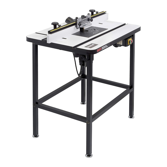
ROUTER TABLE INTENDED USE The unit is intended for stationary operation of portable routers for the cutting of wood or wood TECHNICAL DATA based material when suitable cutter is fitted. Voltage UK & Eire V It is not intended for continuous production or production line use. -
Page 4: Safety
SAFETY tion of dust extraction and collection near gasoline or flammable liquids. facilities, ensure these are connected Keep workshop at a comfortable tem- WARNING: and properly used. perature so your hands are not cold. Connect machines that are used in Observe the safety regulations in the 19. - Page 5 Recommended speeds contact with collet and nut. Ensure 16. Extension of the spanner or tightening are shown in the Trend Routing Cata- cutter and guide bush are concentric. logue and/or website. using hammer blows shall not be permitted.
-
Page 6: Electrical Safety
If you are in doubt, contact an authorised the power input of this tool (see technical data). Trend repair agent or a qualified electrician. The minimum conductor size is 1.5mm n Disconnect the plug from the supply. -
Page 7: Ec Declaration Of Conformity
Harmonized Standard EN 1870-19:2013. 1 x Top guard, top pressure and fixing knob assembly For more information please contact Trend at the following address or refer to back of manual. 1 x Dust spout and fixing screws The undersigned make this declaration on behalf of 2 x Back fence fixing knobs and bolts Trend Machinery &... -
Page 8: Description Of Parts
DESCRIPTION OF PARTS Legs Switch S Hex key 3mm AF Router fixing screw pack B Insert plate K Pushstick Edge planing rod C Table top Insert rings U Edge planing rod AA T11 Quick Raiser locking assembly handle park D Back fence M Table top scales E Fence cheek N Side pressure... -
Page 9: Assembly
ITEMS REQUIRED n Phillips No.2. screwdriver. ® n Router. n Hand tools. n User made bench. n Slotted screwdriver for lead on pin. ASSEMBLY Assembly of Table and Leg Frame (overview) Insert plate supplied fitted into table top. W R T WARNING: Prior to assembly and adjustments always unplug the router table. -
Page 10: Assembly
Leg Frame Assembly (underside view) 50mm Accessory hook Accessory hook Bench Top As- sembly W R T 31.8mm... -
Page 11: Router Compatibility
The insert plate is drilled to suit routers with TBC hole configuration. The following routers use the screws (B) supplied. Screw Make Router Model x Qty TREND T3, T4, T5 B X 2 TREND T9, T10, T11 B X 3 CMT1E... -
Page 12: Mounting Router To Insert Plate
Mounting Router to Insert Plate Re-drilling Insert Plate Only Invert and stand your router onto a suitable n Remove insert plate from table. surface. Remove insert plate from table and place n Remove the plastic base of the router. Alterna- it facing upwards onto the base of your router. -
Page 13: Mounting Table To Workbench
18mm for a user made accessory work- board. The workboard can then be used to mount other routing jigs, so using the WRT as a workbench. 200mm Boards can be secured using M8 600mm bolts and M8 nuts (not included). -
Page 14: Levelling The Insert Plate
Levelling the Insert Plate The insert plate can be levelled to the table top by adjusting the seven set screws with the hex key. To adjust, first loosen the four insert plate fixing screws. Rotate the seven set screws until insert plate is level to table top. -
Page 15: Fitting Back Fence
Slide dust spout Back Fence As- into extrusion sembly from one end be- fore fitting fence cheeks knobs. Use Phillips ® No.2 screwdriver. Scale is self adhesive backed and can be placed onto the top of the fence. Ensure ‘0’ is centred. -
Page 16: Fitting Guards
Fitting Top Guard & Top Pressure Fitting Top Guard & Top Pressure Plastic 5mm max NOTICE: For some applications the thick and thin washer can be swapped over. For exam- ple, when profile scribing using a pushblock. 5mm max 10mm -14-... - Page 17 Fitting Side Pressure Metal W R T 120mm -15-...
-
Page 18: Fitting Mitre Fence And Pushstick
Fitting Mitre Fence W R T Pushstick Park There is a second hook to the left hand side for stor- ing other accessories. -16-... -
Page 19: Fitting Cable Management Clips
Fitting Cable Management Clips 12mm 16mm Rear of table. ® Use Phillips No.2 screwdriver. CRT/4 Fitting Dust Extraction Hose Accessory Ref. CRT/4 (not included) 57mmØ -17-... -
Page 20: Operation
OPERATION No-Volt Release Switch n Plug machine into socket. n Put plug of switch into mains supply. n Switch on router. n Press green button to switch on. To switch off press red button. W R T WARNING: Isolate from power supply when making any ad- justments. -
Page 21: Back Fence Adjustment
Back Fence Adjustment n Adjust back fence position by loosening the two knobs (A) and pushing the fence forwards or backwards. n Lock fence position by tightening the two knobs (A). max. 225mm max. max. n To adjust fence cheeks loosen four back knobs (B). -
Page 22: Edge Moulding And Grooving
Edge Moulding and Grooving n Isolate from power source. n Fit cutter. n Set back fence position. n Set top and side pressures. n Fit guard. n Check all knobs are tight. n Plug into power supply. n Switch on. n Feed right to left. -
Page 23: Stopped Moulding
Fit cutter. n Set back fence position. Fit some stops to back fence using cramps or use accessory limit stop Ref.WRT/2 (1 off). n Fit guard. n Check all knobs are tight n Plug into power supply. n Switch on. -
Page 24: Mitre Fence
Mitre Fence n Isolate from power supply. n Fit cutter. n Adjust angle of mitre fence by loosening knob and turning protractor head to line up angle required with arrow. n Place component onto mitre fence. n Plug into power supply. n Feed right to left holding component securely. -
Page 25: Lead-On Pin
Lead-on Pin n Isolate from power supply. n Fit lead-on pin into threaded hole using a slotted screw- driver. n Move back fence back. n Fit self guided cutter. n Fit top guard. n Plug into power supply. n Support component onto the lead-on pin and swing into cut- ter and contact bearing guide. -
Page 26: Edge Planing
Edge Planing The router table fence features fully independent To position the fence at the 1.4mm setting, slide fence cheeks which allow the fence to double as the rods into the deeper recesses, as shown be- a vertical planer for a 1.4mm or 2.4mm offset. low and tighten the fence cheeks locking knobs. -
Page 27: Accessories
Hose 39mm OD x Ref. CRT/4 32mm ID x 3m. Single Pressures and Limit Stop Ref. WRT/1, WRT/2 Ref. WRT/1 Pair of single pressures that can WRT/1 fit to back fence face extrusion for machining longer lengths of timber. WRT/2 Ref. -
Page 28: Maintenance
Lubrication Please call Trend Customer Services for advice as to how to dispose of unwanted Trend electrical products n Your router table requires no additional in an environmentally safe way or visit www.trend-uk. -
Page 29: Spare Parts - Spare Parts List
Please use only Trend original spare parts. WRT - SPARE PARTS LIST v1.0 03/2017 Qty. Desc. Ref. Table Top WP-WRT/01 Insert Plate WP-WRT/02 Back Fence WP-WRT/03 Fence Cheek WP-WRT/04 Top Frame WP-WRT/05 Crossbar WP-WRT/06 Legs WP-WRT/07 Edge Planing Rod WP-WRT/08... -
Page 30: Spare Parts List
WRT - SPARE PARTS LIST v1.0 03/2017 Qty. Desc. Ref. Washer for Edge Planing Assembly WP-CRTMK3/41 Self Tapping Screw Pan 4mm x 16mm Phillips WP-CRTMK3/42 Machine Screw Carriage UNC 1/4 X 2” Frame Skt WP-WRT/43 Washer for Leg Assembly WP-WRT/44 Machine Screw UNC 1/4 x 1-1/4”... -
Page 31: Spare Parts Diagram
WRT - SPARE PARTS DIAGRAM v1.0 03/2017 -29-... - Page 32 RECYCLABLE © Copyright Trend 2017, 2018. No part of this publication may be reproduced, stored or transmitted in any form without prior permission. Our policy of continuous improvement means that specifications may change without notice. Trend Machinery and Cutting Tools cannot be held liable for any material rendered unusable or any form of consequential loss. E&OE...
Need help?
Do you have a question about the WRT and is the answer not in the manual?
Questions and answers