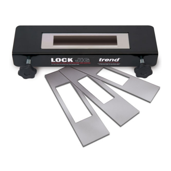
Summary of Contents for TREND LOCK/JIG
- Page 1 LOCK/JIG Aluminium Adjustable Lever Type (Batch EB) Please read these instructions before use.
-
Page 2: Table Of Contents
LOCK/JIG Dear Customer TECHNICAL DATA Thank you for purchasing this Trend product, we Cutter size 12mm hope you enjoy many years of creative and Min. workpiece 34mm productive use. Max. workpiece 58mm Please remember to return your guarantee card Template size 59.8mm x 239mm... -
Page 3: Safety Precautions
LOCK/JIG and balance at all times. Do not use recommended when working SAFETY awkward or uncomfortable hand outdoors. Wear protective hair positions. covering to contain long hair. WARNING: Observe the safety regulations in the 17. Don’t abuse the cable. Never carry 5. - Page 4 15. All fastening screws and nuts should be adhered to. Recommended speeds 4. When using a template guide bush, be tightened using the appropriate are shown in the Trend Routing ensure there is sufficient clearance spanner or key and to the torque Catalogue and/or website.
-
Page 5: Items Enclosed
LOCK/JIG ITEMS ENCLOSED Mortise x4 Face-plate x12 Line-up template x1 ITEMS REQUIRED ■ 1/2” collet plunge router (or 1/4” collet plunge router for face plate only). ■ 30mm guide bush (or 16mm plus collar). ■ 12mm diameter router cutter with suitable shank size. -
Page 6: Description Of Parts
LOCK/JIG DESCRIPTION OF PARTS Use the drawing below as a guide to assemble the jig. A Jig body B Adjustable lever fixing stud C Clamp bar (datum) D Adjustable lever washer E Adjustable lever Spacer finger fixing stud G Spacer finger... -
Page 7: Accessories
30mm Guide Bush Should the correct guide bush not be available to suit your router’s base, you will need to use the Trend UNIBASE in conjunction with a 30mm guide bush, Ref. GB30 or 16mm guide bush Ref. GB160. Ref. UNIBASE Universal Sub-base The Unibase contain screws, a line up bush and pin. -
Page 8: Assembly
LOCK/JIG Setting the Spacer Fingers ASSEMBLY ■ Spacers may need to to be used to ensure ■ Remove the transit washer and nut from the the spigot of the guide bush will not contact middle adjusting lever fixing stud (2) on the jig the door edge when routing. -
Page 9: Choice Of Set-Ups - Option 1
LOCK/JIG Choice of Set-ups Option One Spacer required with T9/T10/T11 router. 12mm Heavy duty router with ⁄ ” collet e.g. T10/T11 Router 30mm Guide Router Cutter Bush Ref. GB30 Ref. TR37X1/2TC See page 8 if a Suitable Plunge Router: Your router should have following... -
Page 10: Option 2
Option Using the Lock Jig with the Trend Hinge Jig ■ If the Lock Jig is to be used in conjunction with the Trend Hinge Jig, use the Guide Bush Collar to bush out the 16mm guide bush (supplied with the Hinge Jig) to 30mm diameter. This makes it unnecessary to change guide bushes between operations. -
Page 11: Fitting The Guide Bush
Ref. GB160 Ref. GB30 Fitting Guide Bush to T10/T11 Router ■ If using the Trend T10/T11 Router, fit a 30mm Fitting Guide Bush to T5 Router ■ If using the Trend T5 Router, purchase and fit guide bush Ref.GB30. Make sure the bush is a GB30. -
Page 12: Steel Templates
Template available, see our website - ⁄ ⁄ 16 x 72mm ⁄ ⁄ 16 x 107mm or call Trend Technical Support. www.trend-uk.com/downloads ⁄ ⁄ 19 x 79mm ⁄ ⁄ 19 x 109mm These are maximum mortise lengths, unless radius ends are squared with a chisel. -
Page 13: Marking Out
LOCK/JIG OPERATION Marking Out ■ Choose the position of the lock carefully. Position the lock with the centre of the spindle aperture at approximately 1m above the floor. Whilst the lock is on the edge of the door, mark the top and bottom of the lock case on the door edge. -
Page 14: Centring The Jig
LOCK/JIG To set up jig with the line-up template Centring the Jig ■ After the lock position has been marked on When using the Lock Jig, the clamp bar is used as the door with a pencil, loosen the two lobe the datum edge. -
Page 15: Routing The Mortise
LOCK/JIG See special note on page 5. Plunge rout a Rout clockwise for clean up series of holes Routing the Mortise ■ Fit the relevant mortise template to the jig body eg A, B, C etc. Ensure that seating for template is free of wood dust. -
Page 16: Finishing
MAINTENANCE Please use only Trend original spare parts and accessories. The jig has been designed to operate over a long period of time with a minimum of maintenance. -
Page 17: Spare Parts - Spare Parts List
LOCK/JIG Please use only Trend original spare parts. LOCK JIG - SPARE PARTS LIST v4.0 07/2013 EB Qty. Desc. Ref. Lock Jig Body WP-LOCK/01 Clamp Bar WP-LOCK/02 Spacer Finger WP-LOCK/03 Mini Knob 15mm Female M5 x 15mm WP-LOCK/04 Adjustable Lever Female M8 WP-LOCK/05 Lobe Knob Male M10 x 40mm Tapped <07/02... - Page 18 LOCK/JIG LOCK JIG - SPARE PARTS DIAGRAM v4.0 07/2013 EB <07/02 -IB-...
- Page 19 RECYCLABLE www.trend-uk.com © Copyright Trend 2013. No part of this publication may be reproduced, stored or transmitted in any form without prior permission. Our policy of continuous improvement means that specifications may change without notice. Trend Machinery and Cutting Tools cannot be held liable for any material rendered unusable or any form of consequential loss.


Need help?
Do you have a question about the LOCK/JIG and is the answer not in the manual?
Questions and answers