Table of Contents
Advertisement
Quick Links
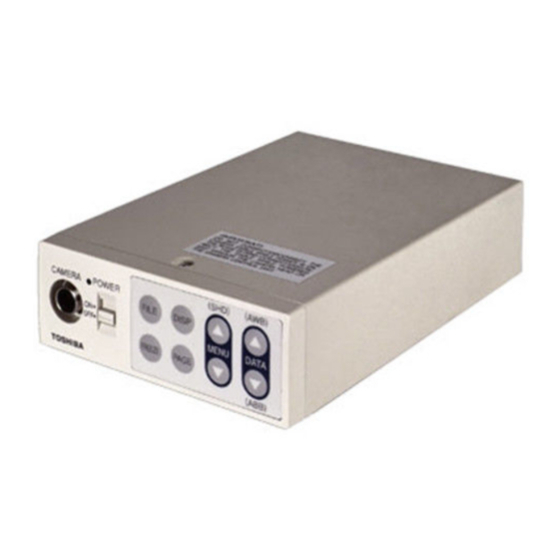
CAMERA CONTROL UNIT
IK-CT2D
U.S.A INFORMATION
NOTE: This equipment has been tested and found to comply with the limits for a Class A digital device, pursuant to Part
15 of the FCC Rules. These limits are designed to provide reasonable protection against harmful interference when the
equipment is operated in a commercial environment. This equipment generates, uses, and can radiate radio frequency
energy and, if not installed and used in accordance with the instruction manual, may cause harmful interference to
radio communications. Operation of this equipment in a residential area is likely to cause harmful interference in which
case the user will be required to correct the interference at his own expense.
USER-INSTALLER CAUTION: Your authority to operate this FCC verified equipment could be voided if
you make changes or modifications not expressly approved by the party responsible for compliance to
Part 15 of the FCC Rules.
Following information is only for EU-member states:
In residential areas this product may cause radio interference, therefore this product must not be used
in residential areas.
The use of the symbol indicates that this product may not be treated as household waste.
By ensuring this product is disposed of correctly, you will help prevent potential negative
consequences for the environment and human health, which could otherwise be caused by
inappropriate waste handling of this product. For more detailed information about the take-
back and recycling of this product, please contact your supplier where you purchased the
product or consult.
This manual is made from recycled paper.
INSTRUCTION MANUAL
For Customer Use
Enter below the Serial No.
w h i c h i s l o c a t e d o n t h e
bottom of the cabinet. Retain
this information for future ref-
erence.
Model No.:
Serial No.:
IK-CT2D
Advertisement
Table of Contents

Related Manuals for Toshiba IK-CT2D


Summary of Contents for Toshiba IK-CT2D
- Page 1 INSTRUCTION MANUAL CAMERA CONTROL UNIT IK-CT2D For Customer Use Enter below the Serial No. w h i c h i s l o c a t e d o n t h e bottom of the cabinet. Retain this information for future ref- erence.
-
Page 2: Safety Precautions
SAFETY PRECAUTIONS Safety icons This manual contains safety instructions that must be observed in order to avoid potential hazards that could result in personal injuries, damage to your equipment, or loss of data. These safety cautions have been classified according to the seriousness of the risk, and the icons highlight these instructions as follows: Indicates a potentially hazardous situation which, if not avoided, could result in death or serious injury. - Page 3 5. Repairs or modifications made by the user or caused to be made by the user and carried out by an unauthorized third party. Notwithstanding the foregoing, Toshiba America Information Systems, Inc.’s (Toshiba's) liabilities shall not, in any circumstances, exceed the purchase price of the product.
-
Page 4: Table Of Contents
Accordingly, Toshiba disclaims any and all liability arising out of the use of the product in any critical applications. - Page 5 (1. 1) Changing the setting in AUTO mode ..................19 (1. 2) Changing the setting in MANUAL mode ................21 (1. 3) Changing the setting in SS (Synchro. Scan) mode ..............21 ..........................22 (2. 1) Changing the setting in AUTO (AGC: Automatic gain control) mode ........22 (2.
-
Page 6: Cautions On Use And Installation
1. CAUTIONS ON USE AND INSTALLATION The following descriptions are for a camera head “IK-CT2H” connected to this camera control unit. damage to the unit and may cause problems. Treat the camera cables carefully to prevent cable problems, If a strong light is imaged, vertical stripes or traverse such as breaks in the cable and loose connections. -
Page 7: Items Controlled By The Screen Display
3. ITEMS CONTROLLED BY THE SCREEN DISPLAY Preset value Item Available selections (Factory setting) AUTO, MANUAL, SS MANUAL AUTO level -100 – 0 – 100 AUTO peak/average 00 : 10 – 10 : 00 00 : 10 AUTO response speed 1 –... -
Page 8: Names And Functions
4. NAMES AND FUNCTIONS FILE button DISP button POWER switch MENU UP POWER LED DATA UP (AWB) button Camera cable for “IK-CT2H” DATA DOWN terminal FREEZE (ABB) button MENU DOWN button FREEZE button PAGE button [Front] REMOTE terminal KEY LOCK switch REMOTE KEY LOCK DVI-D... -
Page 9: Connection
KEY LOCK switch Enables/disables buttons 5. CONNECTION 5. 1 Standard Connection 5. 1. 1 DVI Connection DVI monitor DVI-D TV DVI-D Cable (commercial product) (commercial IK-CT2D Camera product) DVI-D Head Camera Control unit DC IN 12V Camera Cable IK-CT2H (option) -
Page 10: Cautions On Connection
5. 2 Cautions on Connection connected to it. to EN60950-1 in Europe. or use UL listed and/or CSA approved ungrounded type AC adaptor with the specifications described below in U.S.A. or Canada. Current rating : More than 1.5A Connector : HR10A–7P–4S by HIROSE electronics Co. Ltd to tighten the connector completely. -
Page 11: Connector Pin Assignments
5. 3 Connector Pin Assignments The rear panel of the camera control unit has the following connectors: REMOTE KEY LOCK DVI-D DC IN 12V REMOTE terminal USBterminal Clock+ Clock-... -
Page 12: Operation
6. OPERATION A camera head needs to be connected to this camera control unit from this section on. Refer to the item “5. CONNECTION”, connect the equipment correctly. Turn on the connected equipment and the camera. When using the camera for the first time and when replacing the camera head, be sure to perform the ABB adjustment, refer to the item “6.1 Automatic Black Balance”. - Page 13 AWB (Automatic white balance) Change the C.TEMP (color temperature conversion) setting, if necessary. (Refer to the item “7.2 (3) WHT BAL (White Balance)”.) 3200K : Appropriate for indoor shooting. 5600K : Appropriate for outdoor shooting. to disable the color bar pattern or the character display on the monitor. Display Meaning Automatic white balance adjustment finished correctly.
-
Page 14: Scene File
6. 3 Scene File FILE A FILE B FILE C FILE D FILE E while the position is displayed, the scene file cycles as described above. Note: Refer to the item “7.2 (7) Menus” for the contents that can be set in OPTION. -
Page 15: Gain
6. 4 Gain When the image is dark, change the gain (video gain) to get the desired video level. For gain adjustment of the unit, AUTO (Automatic gain control), MANUAL (Manual gain control), OFF (0 dB) modes AUTO (Automatic gain control) When the output is low, gain is automatically adjusted to a suitable video level. -
Page 16: Using Usb To Display Images
6. 6 Using USB to display images *Use a cable that has a mini USB (B type) connector for the USB port on the camera. *Separate viewer software is needed that is compatible with USB video class devices to display the camera images. The following items can be controlled from the computer via a USB cable. -
Page 17: Mode Setting By On Screen Display
7. MODE SETTING BY ON SCREEN DISPLAY again when using the unit next time. When the setting is performed, select the menu of the item to be set. Note: on the output video. These texts on the video are not removable after the video is recorded. Therefore, be aware when you operate the on screen menu, AWB and other menus. -
Page 18: Menus
7. 2 Menus Select the menu to change the setting by referring to the item “7.1 Using the Menus”. ” on the screen moves up and down. Move the “ ” to the item whose setting you wish to change. ( 1 ) SHUTTER (Electronic shutter) The electronic shutter has three modes;... -
Page 19: (1. 1) Changing The Setting In Auto Mode
(1. 1) Changing the setting in AUTO mode Move up and down Select the desired by pushing value by pushing MENU UP, DOWN DATA UP, DOWN Shutter mode AUTO, MANUAL, SS Video level adjustment -100 to 100 Peak and average ratio adjustment 00 10 to 10 00 -- 1 SHUTTER -- (FILE A) Automatic shutter response speed adjustment 1 to 20... - Page 20 (d) Changing the automatic shutter response speed Move the “ [DATA UP] PRESET A PRESET B PRESET C PRESET D PRESET E USER [DATA DOWN] The dark squares indicate the effective region of the image, which is divided into an 8 x 8 grid. PRESET A PRESET B PRESET C...
-
Page 21: (1. 2) Changing The Setting In Manual Mode
(1. 2) Changing the setting in MANUAL mode Move up and down Select the desired by pushing value by pushing MENU UP, DOWN DATA UP, DOWN Shutter mode AUTO, MANUAL, SS -- 1 SHUTTER -- Shutter speed setting (FILE A) OFF, 1/100s, 1/125s, 1/250s, 1/500s, 1/1000s, MODE MANUAL... -
Page 22: (2. 1) Changing The Setting In Auto (Agc: Automatic Gain Control) Mode
( 2 ) GAIN (Video gain) GAIN has three modes; AUTO, MANUAL, OFF. Move the “ OFF. In the OFF mode, gain is fixed to 0dB. (2. 1) Changing the setting in AUTO (AGC: Automatic gain control) mode Move up and down Select the desired by pushing value by pushing... -
Page 23: ( 3 ) Wht Bal (White Balance)
( 3 ) The WHT BAL has two modes; AWB, MANUAL. Move the “ (3. 1) Move up and down Select the desired by pushing value by pushing MENU UP, DOWN DATA UP, DOWN White balance mode setting AWB, MANUAL R PAINT adjustment -10 to 10 -- 3 WHT BAL -- (FILE A) -
Page 24: (3. 2) Changing Gain In Manual Mode
The dark squares indicate the effective region of the image, which is divided into an 8 x 8 grid. PRESET A PRESET B PRESET C PRESET D Custom Selection PRESET E USER Move the “ When AREA is set to USER, the setting can be changed on the area menu. When changing the area, refer to the item “7.2 (8) Setting USER area”. -
Page 25: 4 ) Process1
( 4 ) PROCESS1 Move up and down by Select the desired value by pushing MENU UP, DOWN pushing DATA UP, DOWN Gamma correction ON, OFF Gamma correction level setting -10 to 10 -- 4 PROCESS1 -- (FILE A) Black gamma correction setting LOW, NORMAL, HIGH GAMMA ON/OFF GAMMA BLACK GAMMA... -
Page 26: (4. 3) Changing Black Gamma Correction Level
(4. 3) Changing black gamma correction level Move the “ [DATA UP] NORMAL HIGH [DATA DOWN] * When OFF is selected in GAMMA ON/OFF selection line, the display BLACK GAMMA turns off automatically. So the black gamma correction level cannot be changed. (4. -
Page 27: 5 ) Process2
( 5 ) PROCESS2 Move up and down by Select the desired value by pushing MENU UP, DOWN pushing DATA UP, DOWN Detail gain setting 0 to 31 -- 5 PROCESS2 -- (FILE A) DTL GAIN Detail boost frequency 1 to 16 DTL FREQ HV BALANCE 16/16... -
Page 28: 6 ) Process3
( 6 ) PROCESS3 Move up and down by Select the desired value by pushing MENU UP, DOWN pushing DATA UP, DOWN Matrix color correction ON, OFF -- 6 PROCESS3 -- (FILE A) MATRIX Selection of correction color R, R-Ye, Ye, Ye-G, G, G-Cy, COLOR C, Cy-, B, B-Mg, Mg, Mg-R Phase setting -15 to 15... -
Page 29: 7 ) Option
( 7 ) OPTION Move up and down by Select the desired value by pushing MENU UP, DOWN pushing DATA UP, DOWN OPTION1 -- (FILE A) SCALE SW SCALE SW ON, OFF DTL OUT Detailed signal output ON, OFF MONITOR MONITOR PC, TV FREEZE DISP Freeze display switch ON, OFF... -
Page 30: 8 ) Setting User Area
( 8 ) Setting USER area changed. OFF. Set the output to area menu. Set the output to the area menu by referring to the item “7.2 (1) (1.1) (e) Confirming the contents of the measurement light area selected by automatic shutter” and “7.2 (3) (3.1) (e) Confirming the contents of the zone area selected by AWB”. -
Page 31: Synchro. Scan Operation
7. 3 Synchro. Scan Operation The shutter speed can be set by the horizontal scanning period (1H). ( 1 ) Setting by 1H 1/218H to 217/218H - lets you set a shutter speed to any fraction of the horizontal scanning period from 1/218H to 217/218H in increments of 1. -
Page 32: Before Making Service Call
8. BEFORE MAKING SERVICE CALL Symptom Items to be checked No image Poor color Noise appears... -
Page 33: Specifications
9. SPECIFICATIONS * These conditions are only satisfied when the camera control unit is connected to camera head model # IK-CT2H. Power supply Power consumption Image sensor 0.7mm CMOS Effective pixels Horizontal: 220 pixels, vertical: 220 pixels Output pixels Horizontal: 220 pixels, vertical: 220 pixels Scanning system Progressive Scan frequency... -
Page 34: External Appearance Diagram
10. EXTERNAL APPEARANCE DIAGRAM 186 [7.32] 6 [0.24] FREEZE [Front] 4-M3 BD REMOTE KEY LOCK DC IN 12V DVI-D [Rear] 139 ± 0.15 [5.472 ± 0.006] [1.06]... - Page 35 Limited Warranty – TOSHIBA Camera Control Unit The Imaging Systems Division of Toshiba America Information Systems, Inc. ("ISD") makes the following limited warranty with regard to this Camera Control Unit ("Product"). These limited warranties apply to the Original End-User "You(r)".
Need help?
Do you have a question about the IK-CT2D and is the answer not in the manual?
Questions and answers