Table of Contents
Advertisement
Quick Links
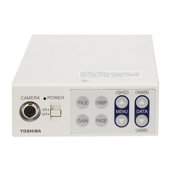
CAMERA CONTROL UNIT
IK-CT1C
FCC NOTICE
This equipment has been tested and found to comply with the limits for a Class A digital device, pursu-
ant to Part 15 of the FCC Rules. These limits are designed to provide reasonable protection against
harmful interference when the equipment is operated in a commercial environment. This equipment
generates, uses, and can radiate radio frequency energy and, if not installed and used in accordance
with the instruction manual, may cause harmful interference to radio communications. Operation of this
equipment in a residential area is likely to cause harmful interference in which case the user will be
required to correct the interference at his own expense.
USER-INSTALLER CAUTION: Your authority to operate this FCC verified equipment could be voided if
you make changes or modifications not expressly approved by the party responsible for compliance to
Part 15 of the FCC Rules.
This Class A digital apparatus complies with Canadian ICES-003.
Cet appareil numérique de la classe A est comforme à la norme NMB-003 du Canada.
Following information is only for EU-member states:
The use of the symbol indicates that this product may not be treated as household waste.
By ensuring this product is disposed of correctly, you will help prevent potential negative
consequences for the environment and human health, which could otherwise be caused by
inappropriate waste handling of this product. For more detailed information about the take-
back and recycling of this product, please contact your supplier where you purchased the
product or consult.
This manual is made from recycled paper.
INSTRUCTION MANUAL
For Customer Use
Enter below the Serial #
w h i c h i s l o c a t e d o n t h e
bottom of the cabinet. Retain
this information for future ref-
erence.
Model #
Serial #
IK-CT1C
Advertisement
Table of Contents

Related Manuals for Toshiba IK-CT1C


Summary of Contents for Toshiba IK-CT1C
- Page 1 CAMERA CONTROL UNIT INSTRUCTION MANUAL IK-CT1C For Customer Use Enter below the Serial # w h i c h i s l o c a t e d o n t h e bottom of the cabinet. Retain this information for future ref- erence.
- Page 2 SAFETY PRECAUTIONS Safety icons This manual contains safety instructions that must be observed in order to avoid potential hazards that could result in personal injuries, damage to your equipment, or loss of data. These safety cautions have been classified according to the seriousness of the risk, and the icons highlight these instructions as follows: Indicates a potentially hazardous situation which, if not avoided, could result in death or serious injury.
- Page 3 5. Repairs or modifications made by the user or caused to be made by the user and carried out by an unauthorized third party. 6. Notwithstanding the foregoing, Toshiba’s liabilities shall not, in any circumstances, exceed the purchase price of the product.
-
Page 4: Table Of Contents
Accordingly, [Toshiba/TAIS] disclaims any and all liability arising out of the use of the product in any critical applications. - Page 5 (6) OPTION........................(6.1) FREEZE INPUT setting..................(6.2) FREEZE MODE setting ..................(6.3) FREEZE DISPLAY setting.................. (6.4) TITLE DISPLAY setting ..................(6.5) TITLE POS (Position) setting................(6.6) Editing TITLE ..................... (6.7) RS232C baud rate ..................... 31 (7) Returning to factory settings ..................32 8 BEFORE MAKING SERVICE CALL............
-
Page 6: Cautions On Use And Installation (For A Camera Head And Camera Control Unit)
1. CAUTIONS ON USE AND INSTALLATION (for a Camera Head and Camera Control Unit) • Handling the unit. The following descriptions are for that a camera head "IK-CT1H" connected to this camera control Do not drop, jolt, or vibrate, as this may result in unit. -
Page 7: Items Controlled By The On Screen Display
3 ITEMS CONTROLLED BY THE ON SCREEN DISPLAY ● Available Item and Preset value in MENU display Preset value Item Available selections (Factory setting) SHUTTER MODE AUTO, MANUAL, SS MANUAL MANUAL OFF, 1/100 ~ 1/10000 MAX EXP. OFF, 1FRM ~ 128FRM LEVEL -100 ~... -
Page 8: Names And Functions
4. NAMES AND FUNCTIONS FILE button DISP button POWER switch MENU UP button POWER LED DATA UP (AWB) button Camera cable terminal for IK-CT1H DATA DOWN button MENU DOWN button FREEZE button PAGE button [Front] S-VIDEO terminal TRIGGER terminal VIDEO terminal DC IN 12V terminal 5 4 3 2 1 REMOTE terminal... -
Page 9: Connection
5. 1 -1 Analog Connection VIDEO Coaxial Cable Monitor 75Ω or S-VIDEO terminal (not supplied) IK-CT1H or S-VIDEO Cable IK-CT1C Camera Head terminal (not supplied) (option) Camera Control unit DC IN 12V DC power supply (option) 5. 1 -2 DVI Connection... -
Page 10: Cautions On Connection
5 2 Caution on Connection When connecting the camera cables, be sure to turn off the camera control unit and any other equipment connected to it. For DC power supply connecting to DC IN 12V terminal, use UL listed and/or CSA approved ungrounded type AC adaptor with the specifications described below. -
Page 11: Operation
6 OPERATION A camera head "IK-CT1H" needs to be connected to this camera control unit from this section on. Refer to the item “5. CONNECTION”, connect the equipment correctly. Turn on the connected equipment and the camera. When using the camera for the first time and when replacing the camera cable and the camera head, be sure to perform the ABB adjustment, refer to the item “6.1 Initializing”. -
Page 12: White Balance
6 2 White Balance For white balance adjustment of this unit, ATW (Automatic Tracking White balance), AWB (Automatic White Balance) and MANUAL (Manual white balance) adjustments are provided. Refer to the items “7.2 (3) WHT BAL (White Balance), 7. MODE SETTING BY THE ON SCREEN DISPLAY”, select the desired mode. - Page 13 Display Meaning AWB OK Automatic white balance adjustment finished correctly. AWB NG Automatic white balance adjustment cannot be performed because the video level is too low. LEVEL LOW Adjust the video level by increasing the illumination or opening the lens iris. AWB NG Automatic white balance adjustment cannot be performed because the video level is too high.
-
Page 14: Scene File
6 3 Scene File Six scene files (A, B, C, D, E, F) are available as user memories for this unit. These are chosen depending on shooting conditions. By using the [FILE] button, the camera operation is changed immediately from the currently selected Scene File to the next. -
Page 15: Mode Setting By The On Screen Display
7 MODE SETTING BY THE ON SCREEN DISPLAY Various settings can be controlled on the unit by using the on screen menu displayed on the monitor. The contents once set are memorized in the scene files (A, B, C, D, E ,F) selected, so if the power turns off, it is unnecessary to set again when using the unit next time. -
Page 16: Menus
7 2 Menus Select the menu to change the setting by referring to the item “7.1 Using the Menus”. When the [MENU UP], [MENU DOWN] buttons are pushed, the “ ” on the screen moves up and down. Move the “ ” to the item whose setting you wish to change. SHUTTER Electronic shutter The electronic shutter has three modes;... -
Page 17: (1.1) Auto Mode
1 1 AUTO mode (a) Changing MAX EXP. setting Move up and down Select the desired by pushing value by pushing MENU UP,DOWN DATA UP,DOWN Maximum exposure time setting in the automatic shutter -- 1 SHUTTER -- mode [ OFF, 1FRM 128FRM ] MODE AUTO long exposure... - Page 18 (c) Changing PEAK/AVE setting Move up and down Select the desired by pushing value by pushing MENU UP,DOWN DATA UP,DOWN -- 1 SHUTTER -- Peak and average ratio adjustment in the automatic shutter mode. (peak:average) [ 00:10 only average ] MODE AUTO [ 10:00 only peak ]...
- Page 19 (e) Changing AREA setting Move up and down Select the desired by pushing value by pushing MENU UP,DOWN DATA UP,DOWN -- 1 SHUTTER -- Automatic shutter zone area setting MODE AUTO [ A, B, C, D, E, USER ] MAX EXP. LEVEL PEAK AVE SPEED...
-
Page 20: (1.2) Manual Mode
(f) Changing AREA DISPLAY / USER AREA Move up and down Select the desired by pushing value by pushing MENU UP,DOWN DATA UP,DOWN -- 1 SHUTTER -- MODE AUTO MAX EXP. LEVEL Displaying the available picture area in the automatic PEAK AVE shutter. -
Page 21: (1.3) Ss (Synchro. Scan) Mode
1 3 SS (Synchro. Scan) mode Move up and down Select the desired by pushing value by pushing MENU UP,DOWN DATA UP,DOWN -- 1 SHUTTER -- Shutter speed setting MODE 260/525H, OFF, 1FRM 128FRM ] 9 525H long exposure Move the “ ” to SS by pushing [MENU UP], [MENU DOWN] buttons. Select the shutter speed by pushing [DATA UP], [DATA DOWN] buttons. -
Page 22: Gain (Video Gain)
2 GAIN (Video gain) GAIN has three modes; AUTO, MANUAL, OFF. Move the “ ” to MODE, push the [DATA UP], [DATA DOWN], and select one of the three modes : AUTO, MANUAL, OFF. In the OFF mode, gain is fixed to 0dB. 2 1 GAIN mode Move up and down Select the desired... -
Page 23: (2.3) Manual Mode
Changing PRIORITY setting Move up and down Select the desired by pushing value by pushing MENU UP,DOWN DATA UP,DOWN -- 2 GAIN Setting the priority of the automatic gain control and long exposure MODE AUTO [ AGC>LONG, LONG>AGC ] MAX GAIN AGC>LONG: takes priority to AGC to long exposure. -
Page 24: Wht Bal (White Balance)
3 WHT BAL (White Balance) The WHT BAL has three modes; AWB, ATW, MANUAL. 3 1 WHT BAL mode Move up and down Select the desired by pushing value by pushing MENU UP,DOWN DATA UP,DOWN White balance mode setting AWB, ATW, MANUAL -- 3 WHT BAL R PAINT (offset red) adjustment -10 to 10 MODE... -
Page 25: (3.3) Atw Mode
3 3 ATW mode (a) Changing R PAINT (offset red) Move the “ ” to R PAINT by pushing [MENU UP], [MENU DOWN] buttons. Select the desired value of red paint by pushing [DATA UP], [DATA DOWN] buttons. DATA UP Red is increased. -
Page 26: Process
4 PROCESS Move up and down Select the desired by pushing value by pushing MENU UP,DOWN DATA UP,DOWN Gamma correction ON, OFF -- 4 PROCESS -- GAMMA ON/OFF ON Detail gain setting OFF, 1 to 10 DTL GAIN Digital noise reduction ON,OFF PEDESTAL Pedestal setting -10 to 10 4 1 Gamma correction ON/OFF... -
Page 27: Matrix(Matrix Color Correction)
5 MATRIX(Matrix color correction) Move up and down Select the desired by pushing value by pushing MENU UP,DOWN DATA UP,DOWN Matrix color correction ON, OFF -- 5 MATRIX -- <FILE A> Red hue setting Yellow hue setting MATRIX Red gain setting Yellow gain setting R HUE Ye HUE... -
Page 28: (6.1) Freeze Input Setting
6 OPTION 6 1 FREEZE INPUT setting Move up and down Select the desired by pushing value by pushing MENU UP,DOWN DATA UP,DOWN FREEZE INPUT mode -- 6 OPTION -- [ FRONT, TRIG ,TRIG “ ” “ ” FRONT setting is set when FREEZE button on front FREEZE INPUT... -
Page 29: (6.3) Freeze Display Setting
6 3 FREEZE DISPLAY setting Move up and down Select the desired by pushing value by pushing MENU UP,DOWN DATA UP,DOWN -- 6 OPTION -- FREEZE display setting FREEZE INPUT FRONT FREEZE MODE FIELD FREEZE DISP TITLE DISP TITLE POS TOP LEFT EDIT TITLE BAUD RATE... -
Page 30: (6.5) Title Pos (Position) Setting
6 5 TITLE POS (Position) setting Move up and down Select the desired by pushing value by pushing MENU UP,DOWN DATA UP,DOWN -- 6 OPTION -- FREEZE INPUT FRONT Title display setting FREEZE MODE FIELD TOP LEFT, TOP RIGHT, FREEZE DISP BOTTOM LEFT, BOTTOM RIGHT TITLE DISP TITLE POS... -
Page 31: (6.6) Editing Title
6 6 Editing TITLE Move up and down Select the desired by pushing value by pushing MENU UP,DOWN DATA UP,DOWN -- 6 OPTION -- FREEZE INPUT FRONT FREEZE MODE FIELD FREEZE DISP TITLE DISP Edit title setting TITLE POS TOP LEFT Displaying a menu for editing title (as below) by pushing EDIT TITLE DATA UP/DOWN. -
Page 32: Returning To Factory Settings
7 Returning to factory settings The contents of each scene file can be returned to the factory default status (preset status). (1) Select a scene file to set to the factory default status by pushing the [FILE] button. (2) If the color bar pattern or characters are displayed on the screen, press the [DISP] button to disable the color bar pattern and character display. -
Page 33: Before Making Service Call
8. BEFORE MAKING SERVICE CALL Symptom Items to be checked Is power supplied correctly? No picture Is the power switch on, and the power LED illuminated? Are the camera and video cables connected correctly? Is the shutter mode set correctly? Is the monitor on, and in working condition? Is the monitor adjusted correctly? Poor color... -
Page 34: Specifications
VBS : 75Ω unbalanced BNC connector Y/C : 75Ω unbalanced S terminal DVI : DVI terminal (DVI-D, DVI-A) Serial data interface (RS-232C) Interface Optional parts IK-CT1H (4.5Φ, a camera head for IK-CT1C) AC-Y415W (AC adapter) Design and specifications are subject to change without notice. -
Page 35: External Appearance Diagram
10. EXTERNAL APPEARANCE DIAGRAM Unit : mm [inch] 12.8 [0.5] 186 [7.32] [Front] 4-M3 (Depth 5 [0.19]) [Rear] [1.06] 139±0.15 [5.47±0.005]... - Page 36 Limited Warranty – TOSHIBA CCD Camera The Imaging Systems Division of Toshiba America Information Systems, Inc. ("ISD") makes the following limited warranties with regard to this CCD Camera ("Product"). These limited warranties extend to the Original End-User ("You[r]"). One (1) Year Limited Warranty of Labor and Parts ISD warrants that this Product will perform in accordance with specifications for a period of one (1) year from the date of purchase by the Original End-User.
Need help?
Do you have a question about the IK-CT1C and is the answer not in the manual?
Questions and answers