Advertisement
Quick Links
Advertisement

Subscribe to Our Youtube Channel
Related Manuals for HobbyKing Gulfstream G500 ARF


Summary of Contents for HobbyKing Gulfstream G500 ARF
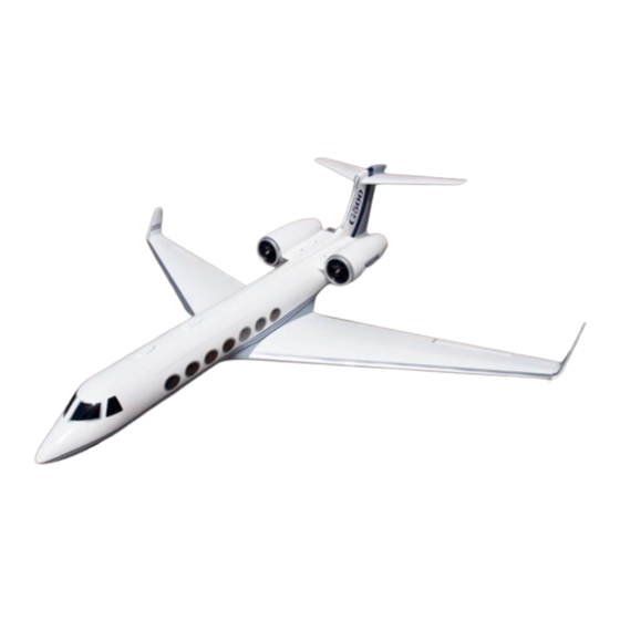
- Page 1 Assembly manual Specs: Wing Span: 2048mm Fuselage Length: 1794mm Wing Area: 46.8 dm!
- Page 2 Step 1: Assembling the ailerons, elevator, rudder and flaps. The aircraft is supplied with its control surfaces attached; however they are not glued in place. To attach them securely, first remove the surfaces and hinges from the plane. Use a small drop of CA glue to secure each hinge to the control surface, making sure appx.
- Page 3 Step 3: Installing the servos Locate the seven servo door covers and cut the covering film away from each to expose the hole through which the servo horn will pass (2x aileron, 2x flap, 2x elevator and 1x rudder). Next, attach servos to the underside of each of these. This may be done using glue, but ideally you should attach by gluing two small blocks (provided) to the underside of these covers and screwing the servos to these (see below).
- Page 4 the aircraft to the nose. The servos should be installed in the following manner (Underside view) Keep slot towards the nose of the plane Secure these with a screw in each corner. Make sure to pre-drill pilot holes (2mm) to prevent the wood from splitting.
- Page 5 the end of one of these you are more than likely using the wrong one. Finish off the remaining horns, clevises and pushrods and come back to it! Also note that for the ailerons, elevators and rudder, control horns are to be bolted on using the provided M2 nut, bolts and endplates. For the flaps, use 8mm woodscrews to attach the horns.
- Page 6 Elevator servos will require appx. 1.2m of extension. It may be a good idea to use a single 1m extension wire connected to a short Y connector to achieve this. Feed this through the body of the plane, up to the nose and leave a short amount of extension cable hanging out of the holes just drilled.
- Page 7 Step 6: Assembling the main wing landing gear Locate the components seen below. Attach the landing gear to the block provided, and the block to the wing using epoxy (30 minute). Make sure the block sits fully in the wing before the glue sets. Also note the orientation of the bar with respect to the wing, make sure you orient both struts the same way (in other words, either both pointing inwards or both pointing outwards)
- Page 8 Next, attach the cover as shown below. Secure in place with CA or epoxy. You can complete this step by installing wheels and collars. Two collars are to be used, one either side of the wheel. Step 7: Assembling the nose landing gear Locate the following parts.
- Page 9 Slide this assembly into the nose of the aircraft.
- Page 10 Then, secure in place with four M3 bolts. Finally, install a servo in the bay provided and attach a pushrod and clevis. Also add wheels and collars. Step 8: Assembling the main wings First, slide the aluminum rod into the fuselage, then slide the wings onto it.
- Page 11 Secure using the four M5 nuts provided. Also note that you may have to enlarge the holes in the wings and fuselage to 5mm as during painting and transit, the diameter of these holes effectively shrinks. 250mm 260mm 298mm Draw a border 15mm from one edge Step 9: Installing the EDF sheath Due to the unusual shape of the EDF housing, I suggest installing the sheath (internal duct to...
- Page 12 For this installation, please keep all measurements and cuts as accurate as possible. Once you have done this, roll up the tube and align the border you drew with the opposite edge. Tape in place. Insert this into the front of the engine housing. It should clear both wooden hoops and reach almost to the end as you can see below.
- Page 13 Flush here Not flush here Once you obtain this, cut a hole to pass motor wires through about 50 mm behind the edge you were just cutting. (Alternatively, you can do this after you glue the sheath in place). You may now glue the sheath to the faring.
- Page 14 Attach the fan units to the fuselage as above. It is a good idea to have all power electronics set up at this point. Feed the ESC wires through the fuselage, out the exit provided, through the fairing and out the front of it as this will be next to impossible to do later. To secure the fairings in place, they are screwed into the fiberglass support arms.
- Page 15 Next cut out and attach the outer fairing. This will be held in place using two or three small screws around the perimeter (not shown). Pilot holes will need to be drilled before attachment.
- Page 16 Step 12: Winglets Drill a hole in the wing. Make sure it is in the correct location (i.e. it must correspond with the hole in the winglet and be of the same size!). Next, roughen the surface in preparation for gluing.
- Page 17 Then insert carbon spar and bond using epoxy.
- Page 18 Attention! Step 13: CG and finishing touches Finally, glue windows to the inside of the fuselage using quick drying epoxy and finish off electronics instillation. Make sure the CG is between 175 and 205mm from the leading edge of the wing as below.
Need help?
Do you have a question about the Gulfstream G500 ARF and is the answer not in the manual?
Questions and answers