Table of Contents
Advertisement
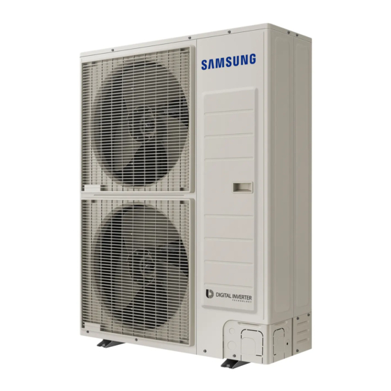
Air conditgioner
Air conditioner
User manual/Installation manual
Installation manual
AR HVSD
AM
XMDCH
Thank you for purchasing this Samsung air conditioner.
Thank you for purchasing this Samsung air conditioner.
Before operating this unit, please read this manual carefully and retain it for future reference.
Before operating this unit, please read this user manual carefully and retain it for
future reference.
Advertisement
Table of Contents

Related Manuals for Samsung AM***XMDCH Series


Summary of Contents for Samsung AM***XMDCH Series
-
Page 1: Air Conditioner
Installation manual AR HVSD XMDCH Thank you for purchasing this Samsung air conditioner. Thank you for purchasing this Samsung air conditioner. Before operating this unit, please read this manual carefully and retain it for future reference. Before operating this unit, please read this user manual carefully and retain it for... -
Page 2: Table Of Contents
Contents Safety precautions ......................3 Outdoor unit type . -
Page 3: Safety Precautions
In order to prevent electric shocks, fires or injuries, always stop the unit, disable the protection switch and contact SAMSUNG’s technical support if the unit produces smoke, if the power cable is hot or damaged or if the unit is very noisy. - Page 4 Safety precautions Installing the unit IMPORTANT: When installing the unit, always remember to connect first the refrigerant tubes, then the electrical lines. Always disassemble the electric lines before the refrigerant tubes. Upon receipt, inspect the product to verify that it has not been damaged during transport. If the product appears damaged, DO NOT INSTALL it and immediately report the damage to the carrier or retailer (if the installer or the authorized technician has collected the material from the retailer.) After completing the installation, always carry out a functional test and provide the instructions on how to operate the air...
-
Page 5: Outdoor Unit Type
Outdoor unit type Shape Model Cooling and Heating 1phase AM060✴XMDCH✴ Installation combination You must install the indoor unit that uses R410A only. If sum capacity of the combined indoor units exceeds the capacity of an outdoor unit, the capacity of each indoor unit is reduced below the rated capacity. -
Page 6: Deciding To Where To Install The Outdoor Unit
Deciding to where to install the outdoor unit Decide the installation location based on the following condition and obtain the user’s approval. Avoid a place that may disturb your neighbor. Noise may occur from the outdoor unit and the discharged air may run into the neighborhood. - Page 7 Install the indoor unit away from any interfering sources such as radio, computer, stereo equipment and also select a place where the electrical wiring work and an indoor unit installation are possible. CAUTION - Especially keep the unit at least 3m (9.84ft) away from the electrical equipment in an area where weak electromagnetic waves are generated and install the protection tube to protect the main power cable and communication cable.
-
Page 8: Installation Location
Installation location Make a space for ventilation and service as seen in the picture. When multiple outdoor units are combined for installation, allow enough space for ventilation against a wall. If the ventilation space is not allowed, product malfunction may occur. The side with logo is the front side of the outdoor unit. - Page 9 When installing more than 1 outdoor unit Unit: mm (inch) ❋ When 3 sides of the outdoor unit are blocked by the wall 300 (12) or 600 (24) or 600 (24) or 600 (24) or more more more more ❋ When the walls are blocking front and the rear of the outdoor units 600 (24) or more 600 (24) or more ❋...
-
Page 10: Installation And Base Ground Work For An Outdoor Unit
Installation location Moving the Outdoor Unit Select the moving route in advance. Be sure that moving route is safe from the weight of the outdoor unit. Do not slant the product more than 30˚ when carrying it. (Do not lay the product down sideways.) The surface of the heat exchanger is sharp. - Page 11 Base ground work Install the outdoor unit horizontally on the ground 150mm (6 inch) or more Drain hole 150mm (6 inch) or more < When installing on the ground > < When installing on the roof > The outdoor unit should be supported within the range of measurement below for base ground work. Unit: mm (inch) Anchor bolt position 620 (24.40)
-
Page 12: Refrigerant Pipe Installation
Refrigerant pipe installation Refrigerant pipe work The length of refrigerant pipe should be as short as possible and the height difference between an indoor unit and outdoor unit should be minimized. The piping length between the outdoor unit and the indoor unit may not exceed the allowable piping length, height difference, and the allowable length after branching is done. - Page 13 Selecting refrigerant pipe Temper grade and minimum thickness of the refrigerant pipe Outer diameter [mm (inch)] Minimum thickness [mm (inch)] Temper grade Ø6.35 (1/4) 0.7 (0.028) Ø9.52 (3/8) 0.7 (0.028) Annealed Ø12.70 (1/2) 0.8 (0.031) Ø15.88 (5/8) 1.0 (0.039) Ø19.05 (3/4) 0.9 (0.035) Drawn Ø22.22 (7/8)
- Page 14 Refrigerant pipe installation Selecting Y-joint Select the first Y-joint according to main pipe size of each outdoor unit capacity. Select the other Y-joints according to the total indoor unit capacity under the selected Y-joint. Selecting the first Y-joint Other Y-joints Outdoor unit capacity Total indoor unit capacity under the Y-joint model...
- Page 15 Direction of the pipe when brazing Brazing the pipe should be done with the pipe headed downward or horizontally. Avoid brazing with the pipe headed upward. The test liquid used to detect leakage after pipe brazing should be the designated one. The use of the test liquid containing sulfur element may cause pipe corrosion.
- Page 16 Refrigerant pipe installation Tightening flare connection area Check that the flaring is properly made. Align the center of the piping and sufficiently tighten the flare nut with fingers. Finally, tighten the flare nut with torque wrench until the wrench clicks. When tightening the flare nut with torque wrench, ensure the direction for tightening follows the arrow on the wrench.
- Page 17 Pipe installation for an outdoor unit Pipe direction The refrigerant pipe can be pulled out from front, flank, rear, and bottom side, so install it depending on the installation site condition. CAUTION Caution for using knock-out hole Make sure not to damage the exterior of the outdoor unit. Remove all burrs at the edge of the knock-out hole and apply the paints it to prevent rust.
- Page 18 Refrigerant pipe installation Refrigerant pipe installation examples Using a Y-joint Using a Y-joint/EEV kit Using a header joint Using a header joint/ Y-joint Allowable length of the refrigerant pipe and the installation examples Connection by Y-joint Outdoor unit Connection by Y-joint/EEV kit Outdoor unit...
- Page 19 Classification Y-joint connection Y-joint / EEV kit connection The distance between the outdoor unit and the farthest indoor unit ≤ 150m (492’) Actual Ex) 8 indoor units Ex) 6 indoor units Length a+b+c+d+e+f+g+p≤ 150m (492’) a+b+c+d+j ≤ 150m (492’) Maximum Outdoor unit Equivalent allowable...
- Page 20 Refrigerant pipe installation Connection by header joint Outdoor unit Header joint Indoor unit Connection by Y-joint/header joint Outdoor unit Header joint Y-joint Indoor unit Classification Header joint connection Y-joint / header joint connection The distance between an outdoor unit and the farthest indoor unit ≤ 150m (492’) Actual Ex) 8 indoor units Ex) 8 indoor units...
- Page 21 ❋ When the equivalent length between an outdoor unit and the farthest indoor unit exceeds 90m (295’), upgrade the low pressure pipe of the main pipe one step. ❋ Note 1) When indoor unit is located at higher level than outdoor unit, allowable height difference is 40m(131ft), but when the indoor unit is located at lower level than outdoor unit, allowable height difference is 50m(164ft).
- Page 22 Refrigerant pipe installation Correct use Incorrect use (The insertion depth of connecting pipe) (The insertion depth of connecting pipe) Basic specification Connecting pipe Connecting pipe When cutting connection part Connecting pipe Connecting pipe When inserting connecting pipe into the Y-joint, please comply with the installation regulation. CAUTION Refrigerant header joint installation Select the reducer fitted on the diameter of the pipe.
- Page 23 When using A~J type of header joint, connect the header joint to the pipe with provided reducer. When using K~Z type of header joint, connect the header joint to the pipe by cutting the provided reducer CAUTION properly. Connect the header joint in order respecting the number of the indoor unit. Connect the indoor unit as the highest capacity comes first.
- Page 24 Refrigerant pipe installation Performing air tightening test Use tools for R410A only to prevent the inflow of foreign substances and to resist the internal pressure. Use dry Nitrogen gas to do an airtight test as below. Apply pressure to the liquid side pipe, gas If you apply pressure more than 4.1 MPa (gauge pressure), 595 psig., side pipe with Nitrogen gas of 4.1 MPa (gauge the pipes may be damaged.
- Page 25 Vacuuming a pipe and an indoor unit Use the tools for R410A only to prevent the inflow of foreign substances and resist against the internal pressure. Use the vacuum pump with the check valve to prevent pump oil from flowing backward while the vacuum pump is stopped suddenly.
- Page 26 Refrigerant pipe installation Selecting additional refrigerant charging Basic refrigerant The basic amount of additional refrigerant charged at a factory Factory charge Model Refrigerant AM060MXMDCH✴ R410A Charging additional refrigerant The amount of refrigerant charging for pipe + The amount of additional refrigerant charging the amount of refrigerant correction charging for an indoor unit.
- Page 27 [Unit: kg(lb)] Capacity(kBtu) Model V-AHU 0.33 0.83 0.88 1.18 1.27 (AM✴✴✴JNZDC✴/AA) (0.73) (1.10) (1.10) (1.83) (1.94) (2.60) (2.80) Ex) When the indoor unit AM023FN1DCH/AA and AM052FNDNCH/AA are installed Additional refrigerant charging = 250g + 450g = 700g 3) The total amount of additional refrigerant charging = the amount of refrigerant charging for pipe + the amount of refrigerant for each indoor unit.
- Page 28 Refrigerant pipe installation Insulating the refrigerant pipes and branch joints Check for gas leakage before completing (the hose and pipe insulation) and if there is no sign of leakage, make sure to insulate the pipes and hoses. Use EPDM material insulator that meets the following conditions. Test item Unit Standard...
- Page 29 Insulating refrigerant pipe You must insulate refrigerant pipe, Y-joint, header joint, and pipe connection area. If you insulate the pipes, the condensed water does not fall from the pipes. Check if there are any insulation cracks on the bent pipe. Clamp Insulation Insulation...
- Page 30 Refrigerant pipe installation Insulating the header joint Fasten the header joint using a cable tie and cover the connected part. Insulation Insulate the header joint and the brazing part and wrap the connected part with an adhesive insulation tape to prevent dew formation. Adhesive insulation Insulation after brazing a stopper tape...
-
Page 31: Wiring Work
Wiring work Wiring work should be performed in accordance with related laws such as ‘Technical specification on electric installation’ , ‘Wiring regulations’ or ‘Installation manual’ . Copper cable should be used for wiring work and all the wires or parts should be rated products. Wiring work should be performed by a company certified by an electric power company. - Page 32 Wiring work Overall System Configuration Connection of the power cable (1 phase 2 wires) Distribution board Outdoor unit Indoor unit 1 phase 1 phase 2 wires 2 wires 208V-230V 208V-230V MCCB + ELCB ELCB MCCB + 208V-230V Earth Communication cable Earth Wired remote controller...
- Page 33 Specification for circuit breaker and power supply cord Power supply cord is not supplied with air conditioner. Select the power supply cord in accordance with relevant local and national regulations. Wire size must comply with the applicable local and national code. The appliance shall be provided with a certified power supply cord and interconnection cord complying with the national regulations of the countries in which the appliance is to be sold.
- Page 34 Wiring work Selecting compressed ring terminal Select a compressed ring terminal of a connecting power cable based on a nominal dimensions for cable. Cover a compressed ring terminal and a connector part of the power cable and then connect it. Silver solder Nominal dimensions for cable 4/6 (0.006/0.009) 10 (0.01) 16 (0.02)
- Page 35 Installing grounding wire Grounding must be done by a qualified installer for your safety. Use the grounding wire by referring to the specification of the electric cable of the outdoor unit. Grounding the power cable The standard of grounding may vary according to the rated voltage and installation place of the air conditioner. Ground the power cable according to the following.
-
Page 36: Grounding Work
Grounding work If the power distribution circuit does not have a grounding or the grounding does not comply with specifications, a ground rod must be installed. The corresponding accessories are not supplied with the air conditioner. 1) Select a grounding rod that complies with the specifications given in the illustration. Copper wire Carbon rod Compressed ring terminal... -
Page 37: Basic Segment Display
Basic segment display Step Display content Display SEG 1 SEG 2 SEG 3 SEG 4 At initial power input Checking segment display “8” “8” “8” “8” SEG 1 SEG 2 SEG 3 SEG 4 While setting Number of communicated communication between Number of connected indoor units indoor and outdoor unit... - Page 38 Setting outdoor unit option switch and key function Setting total number of installed indoor units using K1~K4 K1 K2 K3 K4 1. In the initial, display will show the following. 2. Press and hold simultaneously K1, K2 to enter the setting mode. If you enter the setting mode, display will show the following.
- Page 39 Installing and setting the option with tact switch and explanation of the functions Setting the option □ (1) Press and hold K2 to enter the option setting. (Only available when the operation is stopped) - If you enter the option setting, display will show the following. - Seg 1 and Seg 2 will display the number for selected option.
- Page 40 Setting outdoor unit option switch and key function Optional item Input unit SEG1 SEG2 SEG3 SEG4 Function of the option Remarks Emergency Disabled (Factory Default) operation for Not applicable Main compressor Not applicable malfunction 7-9 (Factory default) Targeted evaporation temperature [°C]. 9-11 Cooling (When low temperature...
- Page 41 Optional item Input unit SEG1 SEG2 SEG3 SEG4 Function of the option Remarks Factory default Oil collection Main interval Shorten the interval by 1/2 Factory default Temperature to Apply setting when the product is The defrost option shortens trigger defrost Main being installed in humid area such the starting time of the defrost...
- Page 42 Setting outdoor unit option switch and key function Optional item Input unit SEG1 SEG2 SEG3 SEG4 Function of the option Remarks Unused option Main Unused option Unused option by this model Unused option Main Unused option Unused option by this model Enabled (Factory default) Restrict excessive capacity Max.
- Page 43 ❋ Even when the outdoor unit power is off, it is dangerous when you come in contact with inverter PCB since it is charged with high DC voltage. ❋ When replacing/repairing the PCB, cut-off the power and wait until the DC voltage is discharged before replacing/ repairing them.
- Page 44 Setting outdoor unit option switch and key function K4 (Press and hold for Display on segment 2 seconds to enter the Displayed content setting) K4 press → Page 1 Page 2 (Number of press) 1 time Main version MAIN Ver. (ex) 1412) 2 times Inverter version INV1...
-
Page 45: Checking Lists After Finishing Installation
Checking lists after finishing installation Before supplying power, measure the power terminal (L, N) and outdoor unit grounding using insulation-resistance tester. - The measured value should be above 30MΩ. You must not measure the communication terminal since the communication circuit may get damaged. Check the short circuit using a circuit tester. -
Page 46: Inspection And Check Operation
Inspection and check operation Precautions before check operation When the outdoor temperature is low, turn on the main power 3 hours before beginning the operation. CAUTION - If you start the operation immediately after turning on the main power, it may cause serious damage to the part within the product. - Page 47 Auto trial operation 1) If the Auto Trial Operation is not completed, normal operation will be prohibited. - When the auto trial operation is not completed, UP (UnPrepared) will appear on the segment after the communication check and restrict compressor from operating. (UP Mode will be cleared automatically when auto trial mode is completed.) - Auto trial operation may take 20 minutes to maximum 2 hours depending on the operation status.
- Page 48 Inspection and check operation Measure to take when E503 error occurs Is the service valve of the outdoor unit Open the service valve of the outdoor unit opened? Is 4way valve and main EEV operating Check the 4way valve and Main EEV normally? Check for leakage.
-
Page 49: Automatic Refrigerant Amount Detection Function (Checking Th Amount Of Refrigerant)
Automatic refrigerant amount detection function (Checking th amount of refrigerant) This function detects amount of refrigerant in the system through refrigerant amount detection operation. Start Press the Tact switch "K2" 5 times Input S-CHECKER signal Satisfy the temperature condition Satisfy the temperature condition Check the amount of refrigerant Check the amount of refrigerant Check stability... - Page 50 Automatic refrigerant amount detection function (Checking th amount of refrigerant) If the temperature is out of the guaranteed range below, exact result will not be obtained. - Indoor: 68~89.6 °F (20~32 °C) Caution - Outdoor: 41~109.4 °F (5~43 °C) If the operation cycle is not stable, the operation of refrigerant amount check may be forcibly finished.
-
Page 51: Trial Operation
Trial operation Check the power supply between the outdoor unit and the cabinet panel. - 1 phase power supply : L, N Check the indoor unit. - Check whether you have connected the power and communication cables correctly. (The communication cables between an indoor unit and outdoor unit are F1, F2.) - Check the thermistor sensor, drain pump/hose, and display are connected correctly. - Page 52 DB68-07029A-00...
Need help?
Do you have a question about the AM***XMDCH Series and is the answer not in the manual?
Questions and answers