Table of Contents
Advertisement
Quick Links
Advertisement
Table of Contents
Troubleshooting

Related Manuals for Omron YRC


Summary of Contents for Omron YRC
-
Page 3: Table Of Contents
CONTENTS YRCX User’s Manual Safety Instructions 1. Safety Information 2. Signal words used in this manual 3. Warning labels 3.1 Warning labels 3.1.1 Warning label messages on robot and controller 3.1.2 Supplied warning labels 3.2 Warning symbols 4. Important precautions for each stage of the robot life cycle 4.1 Precautions for using robots and controllers 4.2 Design 4.2.1 Precautions for robots... - Page 4 CONTENTS YRCX User’s Manual Warranty Important information before reading this manual Introduction About this manual Overview of the YRCX Before using the robot controller (Be sure to read the following notes) Chapter 1 Using the robot safely 1. Emergency action when a person is caught by robot 2.
- Page 5 CONTENTS YRCX User’s Manual 3. Connecting to the power 3.1 Power supply and ground terminals 3.2 AC power connector wiring 3.3 Considering power capacity and generated heat amount 3.4 Installing an external leakage breaker 3.4.1 Selecting condition 3.5 Installing a circuit protector 3.6 Installing an electromagnetic contactor 3.7 Installing a noise filter 3.8 Installing a surge absorber 4.
- Page 6 CONTENTS YRCX User’s Manual 1.6 Connector pin numbers 1.7 Typical input signal connection 1.8 Typical output signal connection 1.9 Dedicated input signal description 1.10 Dedicated output signal description 4-10 1.11 Dedicated I/O signal timing chart 4-12 1.11.1 From the controller power on to servo on 4-12 1.11.2 Controller emergency stop and servo on reset 4-13...
- Page 7 CONTENTS YRCX User’s Manual 2. RS-232C 2.1 Connectors and cables 2.2 Communication specifications 2.3 Connections 2.4 Communication parameter setting 2.5 Communication flow control 2.5.1 Flow control during transmit 2.5.2 Flow control during receive 2.6 Other caution items 3. Ethernet 3.1 Connectors and cables 3.2 Communication specifications 6-11 3.3 Connections...
- Page 8 CONTENTS YRCX User’s Manual 5. USB memory operation 5.1 Saving the data 5.2 Loading the data 6. Execution level 6.1 Changing the access level 7. Safety setting 8. Initialize 8.1 Initializing the data 8.2 Setting the clock 9. Generation 7-10 10.
- Page 9 CONTENTS YRCX User’s Manual 2. Programming box 2.1 Basic specifications 2.2 External view Troubleshooting 1. Alarm messages 1.1 Alarm messages related to the controller 1.1.1 Alarm group number list 1.1.2 Alarm classification number list 1.1.3 Warning number list [ 0] Operation messages [ 1] System events [ 2] Alarm related to the robot operation [ 3] Alarm related to the program file operation A-13 [ 4] Alarm related to the data input...
- Page 11 Safety Instructions Contents 1. Safety Information 2. Signal words used in this manual 3. Warning labels Warning labels 3.1.1 Warning label messages on robot and controller 3.1.2 Supplied warning labels Warning symbols Important precautions for each stage of the robot life cycle Precautions for using robots and controllers Design 4.2.1...
- Page 12 7. Using the robot safely S-23 Movement range S-23 Robot protective functions S-24 Residual risk S-25 Special training for industrial robot operation S-25 KC mark S-26 7.5.1 EMC standards S-26 7.5.2 Examples of EMC countermeasures S-26...
-
Page 13: Safety Information
The precautions listed in this manual relate to this product. To ensure safety of the user’s final system that in- cludes OMRON robots, please take appropriate safety measures as required by the user’s individual system. To use OMRON robots and controllers safely and correctly, always comply with the safety rules and instruc- tions. -
Page 14: Signal Words Used In This Manual
Signal words used in this manual This manual uses the following safety alert symbols and signal words to provide safety instructions that must be observed and to describe handling precautions, prohibited actions, and compulsory actions. Make sure you understand the meaning of each symbol and signal word and then read this manual. DANGER This indicates an immediately hazardous situation which, if not avoided, will result in death or serious injury. -
Page 15: Warning Labels
Warning labels Warning labels shown below are attached to the robot body and controller to alert the operator to potential hazards. To ensure correct use, read the warning labels and comply with the instructions. Warning labels WARNING If warning labels are removed or difficult to see, then the necessary precautions may not be taken, resulting in an accident. - Page 16 Warning label 3 ■ WARNING Improper installation or operation may cause serious injury. Before installing or operating the robot, read the manual and instructions on the warning labels and understand the contents. Instructions on this label • Be sure to read the warning label and this manual carefully to make you completely understand the contents before attempting installation and operation of the robot.
- Page 17 Electrical shock To avoid hazard Wait at least 100 seconds after power-off before opening the covers (*). * These are precautions for OMRON and distributors' service personnel. Customers must not attempt to open the covers. 90K41-001390 Warning label 6 (Controller)* ■...
-
Page 18: Supplied Warning Labels
3.1.2 Supplied warning labels Some warning labels are not affixed to robots but included in the packing box. These warning labels should be affixed to an easy-to-see location. Warning label is attached to the robot body. Warning label comes supplied with the robot and should be affixed to an easy-to-see location on the door or gate of the safety enclosure. -
Page 19: Warning Symbols
Warning symbols Warning symbols shown below are indicated on the robots and controllers to alert the operator to potential hazards. To use the OMRON robot safely and correctly always follow the instructions and cautions indicated by the symbols. Electrical shock hazard symbol WARNING Touching the terminal block or connector may cause electrical shock, so use caution. -
Page 20: Important Precautions For Each Stage Of The Robot Life Cycle
Precautions for using robots and controllers General precautions for using robots and controllers are described below. Applications where robots cannot be used OMRON robots and robot controllers are designed as general-purpose industrial equipment and cannot be used for the following applications. DANGER OMRON robot controllers and robots are designed as general-purpose industrial equipment and cannot be used for the following applications. -
Page 21: Design
Design 4.2.1 Precautions for robots Restricting the robot moving speed WARNING Restriction on the robot moving speed is not a safety-related function. To reduce the risk of collision between the robot and workers, the user must take the necessary protective measures such as enable devices according to risk assessment by the user. -
Page 22: Moving And Installation
Do not use in locations exposed to flammable gases WARNING • OMRON robots are not designed to be explosion-proof. • Do not use the robots in locations exposed to explosive or inflammable gases, dust particles or liquid. Failure to follow this instruction may cause serious accidents involving injury or death, or lead to fire. -
Page 23: Precautions For Robot Controllers
Installation environment WARNING OMRON robots are not designed to be explosion-proof. Do not use the robots and controllers in locations exposed to explosive or inflammable gases, dust particles or liquid such as gasoline and solvents. Failure to follow this instruction may cause serious accidents involving injury or death, and lead to fire. - Page 24 Wiring ■ Connection to robot controller The controller parameters are preset at the factory before shipping to match the robot model. Check the specified robot and controller combination, and connect them in the correct combination. Since the software detects abnormal operation such as motor overloads, the controller parameters must be set correctly to match the motor type used in the robot connected to the controller.
-
Page 25: Safety Measures
Safety measures 4.4.1 Safety measures Referring to warning labels and manual WARNING • Before starting installation or operation of the robot, be sure to read the warning labels and this manual, and comply with the instructions. • Never attempt any repair, parts replacement and modification unless described in this manual. These tasks require specialized technical knowledge and skills and may also involve hazards. -
Page 26: Installing A Safety Enclosure
WARNING • During startup or maintenance tasks, display a sign "WORK IN PROGRESS" on the programming box and operation panel in order to prevent anyone other than the person for that task from mistakenly operating the start or selector switch. If needed, take other measures such as locking the cover on the operation panel. •... -
Page 27: Operation
Operation When operating a robot, ignoring safety measures and checks may lead to serious accidents. Always take the following safety measures and checks to ensure safe operation. DANGER Check the following points before starting robot operation. • No one is within the robot safety enclosure. •... - Page 28 Working inside safety enclosures Before starting work within the safety enclosure, always confirm from outside the enclosure that each protective function is operating correctly (see the previous section 2.3). DANGER Never enter within the movement range while within the safety enclosure. See “7.1 Movement range”...
-
Page 29: Automatic Operation
4.5.2 Automatic operation Check the following points when operating the robot in AUTO mode. Observe the instructions below in cases where an error occurs during automatic operation. Automatic operation described here includes all operations in AUTO mode. Checkpoints before starting automatic operation Check the following points before starting automatic operation. - Page 30 Use caution when releasing the Z-axis (vertical axis) brake WARNING The vertical axis will slide downward when the brake is released, causing a hazardous situation. Take adequate safety measures in consideration by taking the weight and shape into account. • Before releasing the brake after pressing the emergency stop button, place a support under the vertical axis so that it will not slide down.
-
Page 31: Inspection And Maintenance
Inspection and maintenance Always perform daily and periodic inspections and make a pre-operation check to ensure there are no prob- lems with the robot and related equipment. If a problem or abnormality is found, then promptly repair it or take other measures as necessary. Keep a record of periodic inspections or repairs and store this record for at least 3 years. -
Page 32: Precautions During Service Work
4.6.2 Precautions during ser vice work Be careful when removing the Z-axis motor WARNING The Z-axis will slide downward when the Z-axis motor is removed, causing a hazardous situation. • Turn off the controller and place a support under the Z-axis before removing the Z-axis motor. •... -
Page 33: Disposal
Disposal When disposing of robots and related items, handle them carefully as industrial wastes. Use the correct disposal method in compliance with your local regulations, or entrust disposal to a licensed industrial waste disposal company. Disposal of lithium batteries When disposing of lithium batteries, use the correct disposal method in compliance with your local regulations, or entrust disposal to a licensed industrial waste disposal company. -
Page 34: Emergency Action When A Person Is Caught By Robot
Make a printout of the relevant page in the manual and post it a conspicuous location near the controller. Cautions regarding strong magnetic fields Some OMRON robots contain parts generating strong magnetic fields which may cause bodily injury, death, or device malfunction. Always comply with the following instructions. -
Page 35: Using The Robot Safely
Using the robot safely Movement range When a tool or workpiece is attached to the robot manipulator tip, the actual movement range enlarges from the movement range of the robot itself (Figure A) to include the areas taken up by movement of the tool and workpiece attached to the manipulator tip (Figure B). -
Page 36: Robot Protective Functions
Robot protective functions Protective functions for OMRON robots are described below. Overload detection This function detects an overload applied to the motor and turns off the servo. If an overload error occurs, take the following measures to avoid such errors: 1. -
Page 37: Residual Risk
Residual risk To ensure safe and correct use of OMRON robots and controllers, System integrators and/or end users imple- ment machinery safety design that conforms to ISO12100. Residual risks for OMRON robots and controllers are described in the DANGER or WARNING instructions provided in each chapter and section. -
Page 38: Kc Mark
We decide models by single robot product (controller, robot and peripheral device) and conform them to the EMC standards. This does not therefore guarantee that the OMRON robot-series product conforms to the EMC standards if only the robot is used independently. The customer who incorporates OMRON robot products into the customer's final system, which will be shipped to or used in Korea, should verify that the overall system conforms to the EMC standards. -
Page 39: Warranty
OMRON's exclusive warranty is that the products are free from defects in materials and workmanship for a period of one year (or other period if specified) from date of sale by OMRON. OMRON MAKES NO WARRANTY OR REPRESENTATION, EXPRESS OR IMPLIED, REGARDING NONINFRINGEMENT, MERCHANTABILITY, OR FITNESS FOR PARTICULAR PURPOSE OF THE PRODUCTS. -
Page 41: Important Information Before Reading This Manual
Important information before reading this manual Introduction About this manual Overview of the YRCX Before using the robot controller (Be sure to read the following notes) - Page 43 OMRON robot controller safely and correctly. About this manual Warnings and cautions listed in this manual relate to OMRON robot controllers. To ensure safety of the user's final system that includes OMRON robots and controllers, please take appropriate safety measures as required by the user's individual system.
- Page 44 For details about CE marking compliance, refer to the "Safety standards application guide". Additionally, to make the system applicable to the CE marking, select the YRCX CE specifications. This manual explains how to handle and operate the OMRON robot controllers correctly and effectively, as well as I/O interface connections.
- Page 45 Before using the robot controller (Be sure to read the following notes) Please be sure to perform the following tasks before using the robot controller. Failing to perform these tasks will require the return-to-origin for setting the origin position each time the power is turned on or may cause abnormal operation (vibration, noise).
-
Page 47: Chapter 1 Using The Robot Safely
Chapter 1 Using the robot safely 1. Emergency action when a person is caught by robot 2. Emergency stop Emergency stop release and alarm reset 3. Power-ON procedures 4. Usage environments... -
Page 49: Emergency Action When A Person Is Caught By Robot
Emergency action when a person is caught by robot If a person should get caught between the robot and mechanical part such as the installation base, or get captured by the robot, free the person by following the instructions below. For axis not equipped with a brake Put the robot into the emergency stop status to shut off the motor power to the robot. -
Page 50: Emergency Stop
Step 5 Use the cursor keys ( / ) to select Step 5 Brake release confirmation screen [OK] and press to release the brake. For the vertical axis, when the brake is released, the vertical axis may drop. Therefore, check that the vertical axis is supported by the table, etc., and then release the brake. - Page 51 Step 1 Turn the emergency stop button clockwise to release the emergency stop status. Step 2 Reset the alarm. Step 2 "QUICK MENU" screen Press on the programming box. The "QUICK MENU" screen will appear. Use the cursor keys ( ) to select [Alarm Reset], and then press .
-
Page 52: Power-On Procedures
Power-ON procedures This section describes the procedures from turning on the controller power to performing return-to-origin of the robot. CAUTION To connect the programming box to the controller, always use the dedicated cable and connector that come supplied with the programming box. Do not modify the cable and do not connect a relay to the cable. NOTE •... -
Page 53: Usage Environments
Usage environments Operating temperature Operating 0°C to 40°C temperature The ambient temperature should be maintained within a range of 0 to 40°C during operation. This is the range in which continuous operation of the robot controller is guaranteed according to the initial specifications. -
Page 55: Chapter 2 System Overview
Chapter 2 System overview 1. I/O interface overview 1.1 Main system configuration 1.2 Axis configuration for the YRCX 2. Name of each part and control system YRCX external view Controller system 3. Optional devices Programming box Basic key operation Expansion I/O board 4. Basic sequence from installation to operation... -
Page 57: I/O Interface Overview
I/O interface over view Main system configuration Configuration: System for controlling one robot ■ Example: R6YXG500 All the axes on the robot controller are used as axes of the robot 1. Programming box Personal computer External device (PLC etc.) OMRON robot... -
Page 58: Axis Configuration For The Yrcx
Axis configuration for the YRCX The axis configuration for the OMRON YRCX robot controller is shown below. Normal axis Controller Robot [1] Auxiliary axis Normal axis Robot [4] Auxiliary axis Robot [1 to 4] An aggregate of axes making up one robot. Up to four robots can be controlled. -
Page 59: Name Of Each Part And Control System
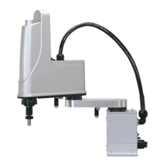
Name of each par t and control system The YRCX external view and the control system basic diagram are shown below. YRCX external view YRCX 11 10 9 15 Panel display (name) Function M1/M2/M3/M4 These connectors are used to drive the servo motor. ROB I/O [1-2/3-4] These connectors are used for the servo motor position signal, origin sensor signal and brake control. -
Page 60: Controller System
Controller system Basic block diagram ■ DRIVER1 RGEN AC IN DRIVER POWER... -
Page 61: Optional Devices
Optional devices Programming box Use of this programming box makes it possible to perform the robot manual operation, program input and editing, teaching, and parameter settings. Emergency stop button Manual lock switch USB connector Enable switch PB connector Basic key operation Keys with three lines allow three kinds of entries. -
Page 62: Basic Sequence From Installation To Operation
Basic sequence from installation to operation … Operator’s manual Basic procedure Refer to: Chapter 3 1. Transport, unpacking Install the controller. 10. Precautions for cable routing and installation • Ground the controller. • Make cable and connector connections. Chapter 4 I/O interface •... -
Page 63: Chapter 3 Installation
Chapter 3 Installation 1. Transport, unpacking 2. Installing the robot controller Installation conditions Installation methods 3. Connecting to the power Power supply and ground terminals AC power connector wiring Considering power capacity and generated heat amount Installing an external leakage breaker 3.4.1 Selecting condition Installing a circuit protector... -
Page 65: Transport, Unpacking
Transpor t, unpacking The robot controller is high precision equipment and is carefully packed in a cardboard box to avoid shocks and vibrations. If the packing box is seriously damaged or dented, please notify your distributor before unpacking. Transport the robot controller carefully with a trolley to prevent damage caused by dropping. Take sufficient care not to apply shocks to the equipment when unpacking. -
Page 66: Installation Methods
• Environment with controller installed on its side or end, or in an inverted position • Environment in which controller connector cables are subject to impact or loads Surrounding clearance ■ figure Install the controller in a well ventilated area, and ensure sufficient clearance on all sides. (See the below.) 50 mm or more 50 mm... -
Page 67: Connecting To The Power
Connecting to the power Attach the power connector to the power cable and insert it into the "AC IN" connector on the front panel of the controller. Power supply and ground terminals CAUTION Before connecting the power cable, be sure to check that the power supply voltage matches the power specifications of your controller. -
Page 68: Ac Power Connector Wiring
AC IN and ground terminals ■ AC power connector wiring Requirements ■ Prepare the following to wire power connectors. Connection lever (provided) Connector (provided) Wire or flat-blade screwdriver. Wiring methods ■ Strip the wire sheath to expose 8 to 9 mm of bare lead. Use either of the methods shown below to insert the wire core into the opening in the power connector, and then ensure that the wire does not come out. -
Page 69: Considering Power Capacity And Generated Heat Amount
Considering power capacity and generated heat amount The required power capacity and generated heat amount depend on the robot model and the number of axes to be controlled. CAUTION The power supply voltage for the robot controller must always be regulated within ±10%. If the voltage drops, the controller detects the voltage drop error to trigger the robot emergency stop. -
Page 70: Installing An External Leakage Breaker
Installing an external leakage breaker Since leakage current flows at high frequencies in the robot controller, always equip the robot controller power connection with an earth leakage current breaker for safety. It is important to choose the optimum sensitivity current rating (I Δ n). (Check the leakage breaker manufacturer's data sheets to select the optimum product compatible with inverters.) 3.4.1 Selecting condition... -
Page 71: Installing A Noise Filter
Installing a noise filter Installation of a noise filter is recommended in order to suppress power line noise. Dimensional outlines of recommended noise filter ■ Manufacturer : TDK-Lambda Corporation Type number : RSHN-2016 127±1 115±0.5 6-M4 2-φ4.5 35±1 Installing a surge absorber It is recommended to install a surge absorber so as to increase the resistance against the surge noise generated by lightning. -
Page 72: Connecting The Absolute Battery
Connecting the absolute batter y The absolute battery has not been connected to the controller at shipment to prevent discharge. After the controller has been installed, be sure to connect the absolute battery before connecting the robot connection cables. Connect the absolute battery to the BAT connector corresponding to the axis used as an absolute type axis. Installing the absolute batter y ■... -
Page 73: Robot Connections
Robot connections Connecting the robot cables Connect the cables to the "M1", "M2", "M3", "M4", "ROB I/O 1-2", and "ROB I/O 3-4" connectors on the front of the controller. The "M1" and "M2" connectors and the "ROB I/O 1-2" connector are intended for axis 1 and 2. Additionally, the "M3"... -
Page 74: Noise Countermeasures
3. Install a noise filter in the cable which connects the controller to the robot. Noise filter ■ Model KBG-M6563-00 (for M1, M3) Model KBG-M6563-10 (for M2, M4) Connected to the OMRON robot Noise filter Connecting the programming box Connect the programming box to the PB connector on the front of the robot controller. -
Page 75: I/O Connections
I/O connections The various input/output (I/O) signals from peripheral equipment can be connected to the robot controller. Each I/O is set with a number, and the I/O connector to be used depends on that number. For more detailed information on inputs and outputs, refer to Chapter 4, "I/O interface" or Chapter 5, "SAFETY I/O interface". -
Page 76: Connecting The Brake Power Supply
Connecting the brake power supply When there are two or more brake axes, an external brake power supply is needed. Prepare a 24 V 10 W power supply for each axis. NOTE The brake power shares with the power source supplied to the parallel I/O board. For details, refer to "1.2 Power supply"... -
Page 77: Methods Of Preventing Malfunctions
10.2 Methods of preventing malfunctions To prevent malfunctions due to noise, take into account the following points. 1. Place a noise filter and ferrite core at a point near the robot controller. Do not bundle the primary wiring and secondary wiring of the noise filter together. Noise filter installation ■... -
Page 78: Checking The Robot Controller Operation
Short-circuit the following pins of the SAFETY connector supplied with the controller. SAFETY connector A1 – A2 A3 – A4 A5 – A6 B1 – B2 B3 – B4 B5 – B6 Programming box SAFETY connector (supplied) Connected to OMRON robot 3-14... -
Page 79: Wiring Example Of Emergency Stop Circuit For Operation Check
11.2 Wiring example of emergency stop circuit for operation check ACIN To main power circuit Controller Main power on/off control Emergency stop Internal power +24V E-STOP1+ E-STOP2+ E-STOP11 E-STOP11 E-STOP12 E-STOP12 E-STOP21 E-STOP21 E-STOP22 E-STOP22 3.3kΩ E-STOP RDY1 E-STOP COM1 Emergency stop 3.3kΩ... -
Page 81: Chapter 4 I/O Interface
Chapter 4 I/O interface 1. I/O interface overview ID settings Power supply Power connector wiring work Connector I/O signals 1.4.1 Standard specification I/O connector signal list 1.4.2 Expanded specification I/O connector signal list Connector pin assignment lists 1.5.1 Standard specification I/O connector 1.5.2 Expanded specification I/O connector Connector pin numbers Typical input signal connection Typical output signal connection Dedicated input signal description 1.10 Dedicated output signal description 4-10... -
Page 83: I/O Interface Overview
I/O interface over view To make the robot applicable to the customer's system, the dedicated or general-purpose I/O interface can be selected for the controller. Add an optional parallel I/O board to the controller to use the I/O interface. The parallel I/O board can select the standard specifications that include the dedicated I/O or the expanded specifications that have only the general-purpose I/O. -
Page 84: Id Settings
ID settings Parallel I/O board IDs (1 to 4) are automatically allocated from the board connection position (in the option slot number order). The option slot numbers are shown on the option slots of the controller main body in the order like "upper left →... -
Page 85: Power Connector Wiring Work
Power connector wiring work Stripping the electric wire ■ Strip the electric wire sheath 7 mm. 7 mm Perform the work while referring to the figures shown below. When using the finger operation lever ■ Push the finger operation lever Insert the electric wire all the way Release the operation lever. -
Page 86: Connector I/O Signals
Connector I/O signals 1.4.1 Standard specification I/O connector signal list NOTE •"CHK1" and "CHK2" are connection check inputs of the standard specification I/O connector. When the ID is set at "1", be sure to short-circuit these inputs. •When the serial I/O is enabled, the dedicated inputs of the option DIO are disabled. I/O No. -
Page 87: Expanded Specification I/O Connector Signal List
1.4.2 Expanded specification I/O connector signal list The IDs are set using the parameter. I/O No. (ID=1) I/O No. (ID=2) I/O No. (ID=3) I/O No. (ID=4) Signal name Reserved DI 10 DI 40 DI 70 DI 120 General-purpose input 10,40,70,120 Reserved DI 11 DI 41... -
Page 88: Connector Pin Assignment Lists
Connector pin assignment lists 1.5.1 Standard specification I/O connector DI01 Servo ON DI12 DI10 SEQ enable DI13 (Spare) ORIGIN DI03 (Spare) DI14 (for INC axis) CHK1 Check input 1 DI15 RESET DI05 (Spare) DI16 ALMRST ORIGIN DI06 STOP DI17 (for ABS axis) General- DI07 (Spare) -
Page 89: Connector Pin Numbers
Connector pin numbers Figure when viewed in the cable connector soldering direction ■ Connector shell type number 10350-52A0-008 SUMITOMO 3M Connector plug type number 10150-3000PE SUMITOMO 3M Typical input signal connection For details regarding the definition of NPN and PNP specifications, refer to "7. I/O connections" in Chapter 3. NPN specifications ■... -
Page 90: Typical Output Signal Connection
PNP specifications ■ DC24V 3.6kΩ Logic Internal circuit 750Ω circuit External CHK1 power CHK2 supply DC24V Typical output signal connection For details regarding the definition of NPN and PNP specifications, refer to "7. I/O connections" in Chapter 3. NPN specifications ■... -
Page 91: Dedicated Input Signal Description
Dedicated input signal description NOTE • Do not input several dedicated inputs at the same time. When inputting continuously, make sure to provide an interval of 100 ms or more between input pulses. • Keep 100 ms or more pulses for the pulse input signal width. •... -
Page 92: Dedicated Output Signal Description
DI15 Program reset input DI15 is used to reset the program. When DI15 is input in the program execution stop status, the robot program is then reset. At this point, all general-purpose outputs and dynamic variables (refer to the YRCX programming manual for details) are reset. - Page 93 DO03 Alarm This output turns on in the following cases. 1) When the emergency stop input contact is open in the servo on status. 2) When a driver unit detects a serious malfunction such as an overload. 3) When the host CPU has stopped due to a serious abnormality or other causes. 4) When the battery is not connected.
-
Page 94: Dedicated I/O Signal Timing Chart
1.11 Dedicated I/O signal timing chart 1.11.1 From the controller power on to ser vo on From the controller power on to ser vo on ■ Conditions: AUTO mode Approx. 3 sec. Control power CPU_OK DO01 Servo ON output DO02 Alarm output DO03 Emergency stop... -
Page 95: Controller Emergency Stop And Servo On Reset
1.11.2 Controller emergency stop and ser vo on reset Emergency stop and ser vo on reset from ser vo on status ■ Conditions: AUTO mode Control power CPU_OK DO01 Servo ON output DO02 Alarm output DO03 Emergency stop Alarm reset input DI16 Servo ON input DI01... -
Page 96: Return-To-Origin
1.11.3 Return-to-origin Return-to-origin ■ Conditions: Servo ON, AUTO mode CPU_OK DO01a Servo ON output DO02a Return-to-origin complete DO11 Stop DI06 Return-to-origin DI14/DI17 100 ms or more Move Robot axis status Stop a) b) c)d) e) f) g) h) i) Return-to-origin a) Return-to-origin input turns on. -
Page 97: Program Reset And Program Execution
1.11.4 Program reset and program execution Program reset and program execution ■ Conditions: AUTO mode Return-to-origin complete DO11 Robot program-in-progress DO13 Program reset status output DO14 Stop DI06 Automatic operation start DI12 Program reset input DI15 100 ms or more d) e) f) Program reset a) Program reset input turns on. -
Page 98: Stopping By Program Stop
1.11.5 Stopping by program stop Stopping by program stop ■ Conditions: AUTO mode Return-to-origin complete DO11 Robot program-in-progress DO13 Stop DI06 Automatic operation start DI12 100 ms or more d) e) Program execution a) Automatic operation start input turns on. b) Robot program-in-progress output turns on. -
Page 99: General-Purpose I/O Signals
1.12 General-purpose I/O signals 1.12.1 General-purpose input signals The standard specifications provide 16 points in total, DI20 to DI27 and DI30 to DI37 while the expanded specifications provide 24 points in total, DI10 to DI17, DI20 to DI27, and DI30 to DI37. These general-purpose inputs can be used arbitrarily. -
Page 100: Ratings
Ratings For details regarding the definition of NPN and PNP specifications, refer to "7. I/O connections" in Chapter 3. Input NPN specifications PNP specifications DC input (positive common type) DC input (negative common type) Method Photo-coupler insulation method Photo-coupler insulation method Input power 24 V DC ±10%, 5.1 mA/point 24 V DC ±10%, 5.5 mA/point... -
Page 101: Chapter 5 Safety I/O Interface
Chapter 5 SAFETY I/O interface 1. SAFETY I/O interface overview Power Connector I/O signals Connection example combining the programming box with external emergency stop circuit 1.3.1 Connection example of controller with CE specifications and PBEX Connections example of dedicated input signal 1.4.1 Emergency stop inputs (E-STOP RDY*, E-STOP COM*) 1.4.2 AUTO mode inputs (AUTO*+, AUTO COM*) Connection example of dedicated output signal 1.5.1 Emergency stop contact outputs (E-STOP*1, E-STOP*2) 1.5.2 Enable switch contact outputs (ENABLE*1, ENABLE*2) 1.5.3 Motor power ready outputs (MP RDY*+, MP RDY*-) -
Page 103: Safety I/O Interface Overview
SAFETY I/O interface over view A SAFETY I/O interface is prepared to construct a robot safety circuit. Use the terminals to construct a safety circuit so that the system including the controller operates toward the safe side. Additionally, connect the I/O terminals correctly and effectively, and then start the operation after checking the operation of the safety circuit sufficiently. -
Page 104: Connection Example Combining The Programming Box With External Emergency Stop Circuit
Connection example combining the programming box with external emergency stop circuit CAUTION • Construct an external emergency stop circuit so that the emergency stop function of the overall system including the controller operates securely. • "E-STOPRDY*" needs a relay or photocoupler drive current of 45 mA or more. 1.3.1 Connection example of controller with CE specifications and PBEX ACIN... -
Page 105: Connections Example Of Dedicated Input Signal
Connections example of dedicated input signal 1.4.1 Emergency stop inputs (E-STOP RDY*, E-STOP COM*) To main power circuit Main power on/off control 45 mA 3.3kΩ 7 mA E-STOP RDY1 E-STOP COM1 45 mA 3.3kΩ 7 mA E-STOP RDY2 DC24V E-STOP COM1 The emergency stop inputs are used to construct a physical emergency stop circuit as a safety protection function of the overall system including the controller. -
Page 106: Connection Example Of Dedicated Output Signal
Connection example of dedicated output signal 1.5.1 Emergency stop contact outputs (E-STOP*1, E-STOP*2) PBEX Controller Emergency stop E-STOP11 E-STOP12 E-STOP21 E-STOP22 The emergency stop contact outputs are used to construct a physical emergency stop circuit as a safety protection function of the system including the controller. To operate the robot, the contact needs to be closed. The emergency stop switch contacts are connected to that of the programming box. -
Page 107: Motor Power Ready Outputs (Mp Rdy*+, Mp Rdy*-)
1.5.3 Motor power ready outputs (MP RDY*+, MP RDY*-) 300 mAmax MP RDY1+ DC30 Vmax MP RDY1- 300 mAmax Load MP RDY2+ DC30 Vmax DC24V MP RDY2- Load This signal turns on when the controller can receive the external main power supply. When this signal turns on, this means that the servo on operation can be performed by supplying the main power and operating the servo on input signal. -
Page 109: Chapter 6 External Communication Interface
Chapter 6 External communication interface 1. Overview Communication overview ONLINE and OFFLINE modes Character code 2. RS-232C Connectors and cables 2.2 Communication specifications Connections Communication parameter setting 2.5 Communication flow control 2.5.1 Flow control during transmit 2.5.2 Flow control during receive Other caution items 3. -
Page 111: Overview
Over view Communication over view To perform the communication between the controller and external device, a communication port (RS-232C interface or Ethernet interface) is used to directly send the robot communication command (SEND command) or send the command through the communication port. As these communications are used individually or together, the robot is applicable to applications using an external communication. -
Page 112: Online And Offline Modes
ONLINE and OFFLINE modes The controller provides two communication modes, ONLINE mode and OFFLINE mode. OFFLINE mode In OFFLINE mode, the communication between the robot and external device is executed with SEND commands in the program. When using the RS-232C port and Ethernet port, specify "CMU" and "ETH", respectively. •... -
Page 113: Character Code
Character code HEX. " STOP XOFF & < ¥ > Note 1: The above character codes are written in hexadecimal. Note 2: SP indicates a blank space. Note 3: Only capital letters can be used for robot language. Small letters are used for program comments and so on. However, these cannot be input on the programming box. -
Page 114: Rs-232C
RS-232C Connectors and cables The RS-232C interface connector is located on the front panel of the robot controller as shown below. RS-232C interface Pin No. Name Description Not used Pin No. Pin No. Receive data Input Send data Output Not used Not used Request to Output... -
Page 115: Communication Specifications
Katakana letters (Japanese phonetic) cannot be output from the communication port if set to 7 bits. Connections The following are examples of connecting to a personal computer using the OMRON communication cable. Using the PC's COM port COM port * The communication cable is optional. -
Page 116: Communication Parameter Setting
Communication parameter setting Parameters and communication mode related to the communication that uses the RS-232C interface are set. There are seven communication parameters. Communication parameter set values Item name Set value Initial value Remarks Sets the mode of the communication with the computer (ONLINE/ LINE ONLINE, OFFLINE ONLINE... -
Page 117: Communication Flow Control
Communication flow control Software flow control (XON/XOFF) and hardware flow control (RTS/CTS) can be set. 2.5.1 Flow control during transmit Flow Control Description 0: None XON (11H) and XOFF (13H) do not affect transmission even when they are received. Stops transmission while CTS is OFF. 1: XON/XOFF Temporarily stops transmission when XOFF is sent from the other party. -
Page 118: Ethernet
Example problems caused by poor connections Improper ground wire connection might cause electrical shock if connector metal parts are touched. External device * YRCX Communication cable AC100 to 200V Connector metal parts Potential Malfunction or breakdown might Ground wire was not at ground Failure to use ground wire might occur when making connection or potential or not connected. -
Page 119: Connectors And Cables
192.168.0.5 Operates as a server IP address 192.168.0.3 YRCX series and performs the robot controller specified operation Server according to the request from the client. Ethernet Client Client Client 192.168.0.10 192.168.0.11 192.168.0.12 Device such as a personal computer becomes a client and connects to the server to give the instruction so as to perform a specified operation. - Page 120 Straight cable ■ This cable is used to connect the robot controller or mating device to the hub. For devices applicable to Auto MDI/MDI-X, the straight cable can be used when the controller and mating device are connected directly. T-568A pin assignments T-568A pin assignments Signal name Wiring color...
-
Page 121: Communication Specifications
192.168.0.254 CAUTION OMRON uses FL HUB (PHOENIX CONTACT) for the operation check. When incorporating a system, it is recommended to use this hub. It is not assumed to use general consumer hubs at factory. Such hubs may have low noise immunity. -
Page 122: Connections
YRCX CAUTION OMRON uses FL HUB (PHOENIX CONTACT) for the operation check. When incorporating a system, it is recommended to use this hub. It is not assumed to use general consumer hubs at factory. Such hubs may have low noise immunity. Therefore, note that OMRON does not warrant the operation of a hub other than that specified above. -
Page 123: Parameter Setting On Controller (Server)
Parameter setting on controller (ser ver) It is necessary for the controller to set the IP address, subnet mask, and gateway port number. These settings are performed from the programming box. Communication parameter set values on controller (server) Item name Initial value Remarks Set value: ONLINE, OFFLINE... -
Page 124: Setting The Communication Mode And Parameters
3.4.1 Setting the communication mode and parameters Step 1 Display the "Ethernet" screen. Setting the Ethernet communication Step 1 Select [System] - [Communication Setting] mode and parameters from the initial screen and press the F1 key (Ethernet). Step 2 Set the communication mode. Press the F2 (ONLINE) or F3 (OFFLINE) key on the "Ethernet"... -
Page 125: System Setting On Personal Computer (Client)
System setting on personal computer (client) The following describes the basic setting procedure by using Windows7 as an example. For details about other OS or device, refer to the relevant manual. For details about setting procedure, refer to the first step guide supplied with Windows7. Additionally, the set values, such as IP address, need to be changed appropriately according to the customer's network environment. -
Page 126: Connection Check Using "Ping
Connection check using "Ping" After the network has been set, check using "ping" if the communication can be performed correctly. "Ping" is a network diagnosis tool that is incorporated into OS as a standard accessory. The following describes how to use "ping" that is incorporated into Windows7. For details about other OS or device, refer to the relevant manual. -
Page 127: Appendix
Step 3 "Telnet" window (1) Step 3 Input "open xxx.xxx.xxx.xxx" next to ">", and then press the ENTER key. Input the IP address of the controller in the "xxx.xxx.xxx.xxx" portion. The controller is then connected and the message "Welcome to YRCX"... - Page 128 Configuration example 2 ■ Multiple controllers are controlled by performing the cascade connection of the hubs. Cross cable Straight cable Cascade port (UPLINK port, MDI port) Hub with cascade port YRCX YRCX YRCX YRCX Personal computer * Similar network can be configured by performing the stack connection of the stackable hubs. In this case, multiple hubs that are connected through the stack connection are recognized as a single large hub from the network.
- Page 129 Configuration example 3 ■ Factory 2 Internet Factory 1 Router Head o ce Router YRCX Controller Personal computer For security, it is recommended to construct a firewall (illegal access prevention mechanism). System setting example IP address Subnet mask Gateway Router in head office 133.215.0.2 255.255.255.0 Personal computer...
-
Page 130: Glossary
3.8.2 Glossar y TCP/IP ■ TCP/IP is a general term for a group of standard protocols for carrying out communications over the Internet around TCP and IP protocols. Computers capable of accessing the Internet all use TCP/IP protocols. The YRCX incorporates the TCP, IP, ICMP, ARP, and TELNET protocols of the TCP/IP protocols. Ethernet ■... - Page 131 The host address can be set freely by each company (organization). However, when connecting to the Internet, it is necessary to make an application to the NIC (JPNIC in Japan) for a network address to get the acquisition. Note that the network address can also be set freely by each company (organization) in the environment where the network is not connected to the Internet in the same manner as the host address.
-
Page 132: General Ethernet Port (Gep)
General Ethernet por t (GEP) Features of GEP ■ GEP function enables YRCX Ethernet port to communicate with several devices at the same time by allocating maximum eight IP addresses or port. In addition, there are differences below between GEP and YRCX Ethernet function. •... -
Page 133: Gep Parameter Setting Method
GEP parameter setting method Step 1 Selecting the GEP number Step 1 Select a GEP number with cursor keys. Pressing the F2 key (INIT) initializes all the GEP communication parameter. Refer to "4.3 Initializing communication parameters" in this Chapter for details. Step 2 Press the F1 key (EDIT) to display GEP edit screen. -
Page 134: Initializing Communication Parameters
Initializing communication parameters Step 1 Display the pop-up screen. Press the F2 key (INIT) on the "GEP SETTING" screen to display a pop-up screen. Step 2 Initialize the communication parameters. Select [OK] with the cursor keys and press the ENTER key to initialize all the GEP communication parameters. -
Page 135: Chapter 7 Controller System Settings
Chapter 7 Controller system settings 1. Overview 2. History 3. Check 4. Property Robot information Option information Clock Version 4.5 Configuration 5. USB memory operation Saving the data Loading the data 6. Execution level Changing the access level 7. Safety setting 8. -
Page 137: Overview
Over view To operate the robot, various settings corresponding to the customer's operation are needed. This Chapter describes how to make the various controller settings and display the information. Additionally, system settings other than the robot operation settings are also described. Item Description History... -
Page 138: Check
Check When selecting [System] - [Check] from the initial "CHECK" screen ■ screen, the "CHECK" screen will appear. The controller is diagnosed. If an error is detected, relevant message will appear. NOTE Even when the 24 V DC power is not supplied to the option DIO, the alarm always occurs. Proper ty When selecting [System] - [Property] from the initial screen, the property screen will appear. -
Page 139: Option Information
Option information "OPTION" screen When pressing the F2 key (OPTION), the "OPTION" ■ screen displays the type and version of the option boards connected to the option slot of the controller. Display Unit name Displays that the option DIO with the NPN DIO_Nm* specifications is installed. -
Page 140: Configuration
• If an abnormal process, such as power shutdown occurs while the data is being saved or loaded, the data is not guaranteed. Saving the data The internal data of the controller is saved into the USB memory. The data will be saved into the "OMRON" folder immediately beneath the USB memory. Step 1... -
Page 141: Loading The Data
Loading the data The data saved in the USB memory is restored to the internal memory of the controller. It is required to the data to have been saved into the "OMRON" folder immediately beneath the USB memory. Step 1... -
Page 142: Execution Level
Execution level The controller can be set to operating levels that permit or prohibit changing programs and point data. Access level Description All operations can be performed. Level 0: Maintainer level To move to this level, a password is required. Only the manual operation and automatic operation can be performed. -
Page 143: Safety Setting
Safety setting The safety parameters are set to safely perform the work with the programming box within the movement range (the safety enclosure) of the system using the robot. WARNING • In "Safety setting", changing the settings from their default values is likely to increase hazards to the robot operator during maintenance or operation. -
Page 144: Initialize
Initialize When selecting [System] - [Initialize] from the "INITIALIZE" screen ■ initial screen, the "Initialize" screen will appear. On this screen, you can initialize the data managed by the controller. Use the F1 key (ALL DATA) to F11 (CLOCK) to select the item to initialize. Valid keys and submenu descriptions on the "INITIALIZE"... -
Page 145: Setting The Clock
Valid keys and submenu descriptions on the "INITIALIZE" screen are shown below. Valid keys Menu Function Initializes all data. Deletes the program data. Deletes the point data. Deletes the point name data. Deletes the shift coordinate data. Deletes the hand definition data. Initializes the parameter data. -
Page 146: Generation
• If the system generation is changed by mistake, this may adversely affect the robot operation or cause serious hazard to the operator. When the system generation needs to be changed, contact your distributor. • If the system generation is changed without consulting your distributor, OMRON shall not be held responsible for any trouble arising from this change. - Page 147 Valid keys Menu Function Sets the I/O related parameters. OPTION Sets the option board related parameters. GRIPPER Sets the gripper related parameters.* TRACKING Sets the tracking system related parameters.* Returns to the previous screen. * Refer to the each manual for details. Step 2 Select the parameter.
-
Page 148: Parameter List
10.3 Parameter list Controller parameters ■ For details about parameters, refer to "10.4 Controller parameters" in this Chapter. Name Identifier Setting range Initial value Unit Incremental Mode control INCMOD 0: INVALID, 1: VALID MOVEI/DRIVEI start pos. MOVIMD 0: KEEP, 1: RESET MOVET start pos. - Page 149 Name Identifier Setting range Initial value Unit Inner side circle minimum radius MINRAD 10 to 100000 5000 0.001mm Speed limit radius 1 CERAD1 10 to 100000 30000 0.001mm Speed limit radius 2 CERAD2 10 to 100000 5000 0.001mm Speed limit 1 SPLMT1 1 to 100 Speed limit 2...
- Page 150 • Set the workpiece weight held at the robot tip for the tip weight of the robot parameters. • The value of the arm length parameter may affect the acceleration. The effective stroke value of each axis needs to be input for the arm length. I/O parameters ■...
-
Page 151: Controller Parameters
10.4 Controller parameters Incremental mode control ‹INCMOD ■ › This parameter sets whether or not the robot is always put in the return-to-origin incomplete status when starting up this controller. Set "0: INVALID" in the case that there are axes whose return-to-origin method are set to "Mark". When this parameter is initialized, "0: INVALID"... - Page 152 Sequence flag ‹SEQFLG› ■ This parameter sets whether the controller executes the sequence program. When this parameter is initialized, "0: INVALID" is set. Setting Meaning 0: INVALID The sequence program execution is not allowed. 1: VALID The sequence program execution is allowed. 3: VALID &...
-
Page 153: Robot Parameters
INPUT/PRINT using channel ‹STDPRN› ■ This parameter sets the PRINT statement output destination channel and INPUT statement input origin channel. When this parameter is initialized, "1: PB" is set. Setting Meaning 1: PB Programming box 2: CMU RS232C port 3: ETH Ethernet port Emergency time ‹EMGTIM›... - Page 154 Origin sequence ‹ORGORD› ■ This parameter sets the order of return-to-origin operation using the axis number (1 to 6). Axes perform return-to-origin operation in order from the left end. Axes that are not set finally perform return-to-origin operation at the same time. When this parameter is initialized, "312456" is set. CAUTION When performing return-to-origin of three or more axes with the return-to-origin method set at the stroke end method, the emergency stop may be activated.
- Page 155 R-axis orientation ‹RORIEN› ■ This parameter sets whether or not the R-axis orientation (posture) is held when performing jog operation on the Cartesian coordinates in the SCARA robot. When this parameter is initialized, "0: KEEP" is set. When the orientation set at "KEEP", the R-axis automatically rotates to hold the current orientation if jog movement is performed on the Cartesian coordinates.
-
Page 156: Axis Parameters
10.6 Axis parameters Plus (+) soft limit ‹PLMT+› Minus (-) soft limit ‹PLMT-› ■ This parameter sets the axis movement range using the upper limit value [plus (+) soft limit] and lower limit value [minus (-) soft limit]. When this parameter is initialized, the value unique to the model is set. When performing point teaching or automatic operation, check that the specified point data is within the soft limit range. - Page 157 Tolerance ‹TOLE› ■ This parameter sets the positioning completion range to the target position when the robot moves. When this parameter is initialized, the value unique to the model is set. When the current position of the robot enters the specified range, this is judged to the positioning completion. NOTE Input the tolerance value with the 0 to 9 keys, "."...
- Page 158 NOTE Input the OUT valid position with the 0 to 9 keys, "." key, and "-" key. When the value input with the keys is a real number (numeric value including a period), the unit is converted into the pulse value. Arch pulse 1 ‹ARCHP1›...
- Page 159 Push judge speed ‹PSHJGSP› ■ The pushing time counting starts when the current axis movement speed lowers the rate specified in this parameter against command movement speed. When "0" is set, the judgement is invalid. When this parameter is initialized, "0" is set. Push method ‹PSHMTD›...
- Page 160 Origin shift ‹ORGSFT› ■ This parameter is used to correct the deviation amount of each axis if the work position deviates after the motor has been replaced and an impact has been applied. When this parameter is initialized, "0" is set. Set the electrical deviation origin position amount to the mechanical origin position of the robot.
- Page 161 Origin direction ‹ORGDIR› ■ This parameter sets the movement direction when the robot performs return-to-origin. When this parameter is initialized, the value unique to the model is set. 0: Minus … The minus (-) direction of the motor position is the return-to-origin direction. 1: Plus …...
- Page 162 Offset pulse ‹OFFSET› ■ This parameter sets the angle to the arm posture or standard coordinate axis in the status where the X, Y, and R-axis motor positions of the SCARA robots are located at their "0"-pulse positions. • X-axis offset pulse …...
-
Page 163: I/O Parameters
10.7 I/O parameters DO at emergency stop ‹EMGCDO› ■ This parameter sets the DO/MO/LO/TO/SO port outputs to RESET/HOLD when the emergency stop is input. When this parameter is initialized, "1: IO_HOLD" is set. Setting Meaning 0: IO_RESET Turns the DO/MO/LO/TO/SO port outputs OFF when the emergency stop is input to the controller. 1: IO_HOLD Holds the DO/MO/LO/TO/SO port outputs when the emergency stop is input to the controller. - Page 164 DO output at program reset ‹RESCDO› ■ This parameter sets the DO/MO/LO/TO/SO port outputs to RESET/HOLD when all programs are reset or the HALT ALL statement is executed. When this parameter is initialized, "0: IO_RESET" is set. Setting Meaning The DO/MO/LO/TO/SO port outputs are reset when executing any of the following operations. •...
-
Page 165: Option Board Related Parameters
Done output port (DO & SO) ‹IOORGOUT› ■ This parameter sets ports to output the return-to-origin status of each axis. When the number of axes exceeds 8, the next port is used to specify 16 axes maximum. When this parameter is initialized, "0" is set. The return-to-origin status is not output when "0"... - Page 166 PROFIBUS station address ‹PBUSADD› ■ This parameter sets the station number (the identifier to each node of the PROFIBUS) of the PROFIBUS-corresponding unit. The setting range is between 1 and 125. When this parameter is initialized, "125" is set. New setting value will be valid after turning off and on the power. Gripper ser vo when emergency stop ‹GEMGMD›...
- Page 167 DeviceNet address ID ‹DEVADD› ■ This parameter sets the DeviceNet station number. When this parameter is initialized, "0" is set. DeviceNet baudrate ‹DEVCOM› ■ This parameter sets the DeviceNet baud rate. When this parameter is initialized, "0: 125kbps" is set. Setting Meaning 125kbps...
-
Page 169: Chapter 8 Periodic Inspection
Chapter 8 Periodic inspection 1. Before carrying out work 2. Maintenance parts 3. Periodic inspections Daily inspections Three-month inspections 4. Replacing the absolute battery 5. Replacing the memory battery... -
Page 171: Before Carrying Out Work
Before carr ying out work In order to operate the robot system safely and more efficiently, carry out the periodic inspection and maintenance. This section describes how to carry out periodic inspections on the controller. Before carrying out the inspection, carefully read and follow the instructions in this chapter and in Chapter 1 "Using the robot safely". -
Page 172: Three-Month Inspections
Three-month inspections Check the fan filter on the back of the controller for dirt and damage. WARNING Turn off the primary power source or the power on the controller inside the control panel. Removing the filter cover Step 1 Step 1 Remove the filter cover. - Page 173 Replacing the memor y batter y ■ Step 1 Loosen the knob on the bottom. Step 1-2 Step 2 Remove the bottom cover, to which the memory battery is secured. Step 3 Disconnect the memory battery connector from the controller main body.
-
Page 175: Chapter 9 Specifications
Chapter 9 Specifications 1. Controller 1.1 Specifications Basic functions External view 2. Programming box 2.1 Basic specifications External view... -
Page 177: Controller
Controller Specifications Connected motor capacity 1600 W or less (in total for 4 axes) Power capacity 2500 VA Dimensions W355 × H195 × D130 (main unit) Weight 6.2kg (main unit) Power supply voltage Single phase 200 to 230 V AC ±10%, 50/60 Hz 4 axes maximum (simultaneous control: 6 axes) Number of controllable axes Up to 16 axes (4 robots) can be expanded through the controller link. -
Page 178: Basic Functions
Dedicated input 8 points, dedicated output 9 points Standard General-purpose input 16 points, general-purpose output 8 points specifications Parallel I/O (Max. 1 board, NPN/PNP specifications) board Expanded General-purpose input 24 points, general-purpose output 16 points specifications (Max. 4 boards, NPN/PNP specifications) Remote I/O DeviceNet board Dedicated I/O: 16 points each... -
Page 179: External View
External view YRCX external view ■ 3- 5.5 10.5 OPTION ROB I/O ROB I/O SAFETY AC IN (PE) M1 BAT1 BAT2 BAT3 BAT4 YRCX 22.5... -
Page 180: Programming Box
Programming box Basic specifications Programming box basic specifications ■ Item PBEX Display screen Color LCD (320 × 240 dot) Emergency stop button Normally-closed contract (with lock function) Enable switch 3-position type Manual lock selector switch 90°, 2-notch Power +12 VDC Ambient temperature for use: 0 to 40 °C, Operating environment Ambient temperature for storage: -10 to 60 °C,... -
Page 181: Troubleshooting
Troubleshooting 1. Alarm messages Alarm messages related to the controller 1.1.1 Alarm group number list 1.1.2 Alarm classification number list 1.1.3 Warning number list [ 0] Operation messages [ 1] System events [ 2] Alarm related to the robot operation [ 3] Alarm related to the program file operation A-13 [ 4] Alarm related to the data input A-15 [ 5] Alarm related to the syntax of the robot language (compile) A-16... -
Page 183: Alarm Messages
Alarm messages Alarm messages related to the controller If an alarm occurs, a relevant alarm code is shown on the 7-segment LED on the front of the controller, and a relevant alarm code and message appears on the screen of the programming box. The alarm code consists of two elements, "group"... - Page 184 Alarm occurrence location list Task *… Task number Startup, memory check, generation Online command Remote command Sequence program Standard input Controller *… Controller number Option board C*O* *… Controller number, option slot number Robot, axis R*/R*A* *… Robot number, axis number Physical motor M*/C*M* *…...
-
Page 185: Alarm Group Number List
1.1.1 Alarm group number list The alarm message is classified into groups [0] to [30] according to the alarm contents. The contents of each group are shown below. Group number Contents [ 0] Operation messages [ 1] System events [ 2] Alarm related to the robot movement range [ 3] Alarm related to the program file operation... -
Page 186: Alarm Classification Number List
1.1.2 Alarm classification number list Axis operation Alarm code Type History Reset method Example in case of error display Correct HALT, HOLD, Break point, 1 to 99 Key release Message Restart operation displayed 100 to 199 CPU start Individual Restart 200 to 399 No point Operation... -
Page 187: 1] System Events
0.19 : Can’t edit Code : &H0000 &H0013 Meaning/Cause The read-only file is being edited. Action Change the file attribute. 0.20 : Illegal command in this mode Code : &H0000 &H0014 Meaning/Cause The specified online command cannot be executed in the current mode. Action Change the mode. - Page 188 : Program ended by "HALTALL" Code : &H0001 &H0004 Meaning/Cause The program execution was terminated by the "HALTALL" command. Action − − − : Program ended by "HALT" Code : &H0001 &H0005 Meaning/Cause The program execution was terminated by the "HALT" command. Action −...
-
Page 189: 2] Alarm Related To The Robot Operation
1.12 : Program stopped by key release Code : &H0001 &H000C Meaning/Cause The RUN key was released in the "Hold To Run" enable status. Action − − − 1.13 : Changed PRINT/INPUT right Code : &H0001 &H000D Meaning/Cause The operation stopped since the "PRINT/INPUT using channel" was changed. Action Change the setting of "PRINT/INPUT channel in use"... - Page 190 2.306 : Movable range cal. failed Code : &H0002 &H0132 a. Preset calculation for the movement path setting is not functioning. Meaning/Cause b. The current position is not within the movement range. a. Change to the correct movement point. Action b.
- Page 191 2.319 : Cannot move (RIGHTY to LEFTY) Code : &H0002 &H013F The interpolation movement to the target point whose hand system is set to "LEFT" was Meaning/Cause attempted when the hand system is set to "RIGHT" on the SCARA type robots. Action Check the current hand system and hand system flag of the point data.
- Page 192 2.331 : Circular arc radius too small Code : &H0002 &H014B Meaning/Cause The "MOVE C" command radius is less than 0.1 mm. Action Change the "MOVE C" command to 0.1 mm or more for circular arc radius. 2.332 : Circular arc radius too large Code : &H0002 &H014C Meaning/Cause...
- Page 193 2.338 : PATH execute error Code : &H0002 &H0152 a. The PATH motion cannot be executed. Meaning/Cause b. The acceleration/deceleration zone distance is too short. c. The speed is too high at the position where the direction changes. a. Reduce the speed setting. b.
- Page 194 2.347 : Not tracking status Code : &H0002 &H015B Meaning/Cause "CTDRIVE" command was executed for the robot without following the conveyor. Change the program so that "CTDRIVE" command is executed after following the conveyor by Action "CTMOVE" command. 2.348 : Over tracking area Code : &H0002 &H015C •...
-
Page 195: 3] Alarm Related To The Program File Operation
2.705 : System error (OPTION) Code : &H0002&H02C1 Meaning/Cause Error occurred in software. Action Contact your distributor. 2.706 : System error (PATH) Code : &H0002&H02C2 Meaning/Cause Error occurred in software. Action Contact your distributor. 2.707 : AXSWEI over Code : &H0002&H02C3 Meaning/Cause The axis weight exceeds the input range. - Page 196 3.206 : Too many breakpoints Code : &H0003 &H00CE Meaning/Cause More than 32 break points were set. Delete unnecessary programs and then set new ones. Action (32 or less break points can be set per program.) 3.207 : Breakpoint doesn't exist Code : &H0003 &H00CF Meaning/Cause...
-
Page 197: 4] Alarm Related To The Data Input
3.238 : Program is already running Code : &H0003 &H00EE Meaning/Cause The program is already running. Action − − − 3.239 : Sequence program is already running Code : &H0003 &H00EF Meaning/Cause The sequence program to revise or delete is running. Action Stop the sequence program. -
Page 198: 5] Alarm Related To The Syntax Of The Robot Language (Compile
4.209 : Point name doesn't exist Code : &H0004 &H00D1 Meaning/Cause The specified point name does not exist. • Input a point name that can be used. Action • Register a new point name. 4.210 : Illegal point name Code : &H0004 &H00D2 Meaning/Cause The specified point name is incorrect. - Page 199 5.203 : Number error Code : &H0005 &H00CB a. The input number is incorrect. Meaning/Cause b. The input expression value is incorrect. a. Input a correct number. Action b. Input a correct expression value. 5.204 : Bit number error Code : &H0005 &H00CC Meaning/Cause The specified bit number is not within 0 to 7.
- Page 200 5.215 : FOR variable error Code : &H0005 &H00D7 Meaning/Cause The variable name for "NEXT" statement differs from that for the corresponding "FOR" statement. Action Use the corresponding variable names. 5.216 : WEND without WHILE Code : &H0005 &H00D8 Meaning/Cause There is no "WHILE"...
- Page 201 5.223 : ELSE without ENDIF Code : &H0005 &H00DF Meaning/Cause There is no "ENDIF" statement corresponding to the "ELSE" statement. • Delete the "ELSE" statement. Action • Add "ENDIF" statement corresponding to the "ELSE" statement. 5.224 : END SUB without SUB Code : &H0005 &H00E0 a.
- Page 202 5.231 : Undefined label Code : &H0005 &H00E7 Meaning/Cause An undefined label was used. Action Define the undefined label. 5.232 : Undefined user function Code : &H0005 &H00E8 Meaning/Cause Undefined function was called. Action Define the undefined function. 5.233 : Undefined HAND Code : &H0005 &H00E9 Meaning/Cause...
- Page 203 5.240 : Illegal command in procedure Code : &H0005 &H00F0 Meaning/Cause The command cannot be executed inside the procedure (between "SUB to END SUB" statements). Action Delete the target command. 5.241 : Illegal command outside procedure Code : &H0005 &H00F1 Meaning/Cause The command cannot be executed outside the procedure (between "SUB to END SUB"...
- Page 204 5.248 : END SELECT without SELECT Code : &H0005 &H00F8 Meaning/Cause There is no "SELECT" statement corresponding to the "END SELECT" statement. • Delete the "END SELECT" statement. Action • Add a "SELECT" statement corresponding to the "END SELECT" statement. 5.249 : SELECT without END SELECT Code : &H0005 &H00F9...
-
Page 205: 6] Alarm Related To The Robot Language Execution
5.256 : Subscript mismatch Code : &H0005 &H0100 Meaning/Cause The numbers of the array declared by DIM and the subscript do not correspond. • Make the number of the subscript correspond to that of declared array. Action • Change the number of the subscript specified by the array declaration. •... - Page 206 6.204 : Point doesn't exist Code : &H0006 &H00CC Meaning/Cause Assignment, movement or reference to an undefined point was attempted. Action Define the point. 6.205 : Coordinate type error Code : &H0006 &H00CD a. Arithmetic operations of joint coordinate point data and Cartesian coordinate point data were attempted.
- Page 207 6.212 : RESTART without START Code : &H0006 &H00D4 Meaning/Cause The "RESTART" command was executed for a task not executed by the "START" command. Action Confirm the execution of "START" command. 6.213 : RESTART without SUSPEND Code : &H0006 &H00D5 Meaning/Cause The "RESTART"...
- Page 208 6.220 : Not execute CALL Code : &H0006 &H00DC Meaning/Cause The "CALL" command was not executed. Action Confirm the execution of "CALL" command. 6.225 : No sufficient memor y for OUT Code : &H0006 &H00E1 Since 17 or more the "OUT" commands were executed in parallel, the command cannot be Meaning/Cause executed because of insufficient memory.
- Page 209 6.233 : MARK method is not allowed Code : &H0006 &H00E9 Return-to-origin was performed by "ORIGIN" statement or dedicated input while the return-to- Meaning/Cause origin method for incremental type axes are set to "Mark". Action Change the return-to-origin method. 6.234 : Port number error Code : &H0006 &H00EA •...
- Page 210 6.252 : Data out of range Code : &H0006 &H00FC Meaning/Cause The specified value is out of the input range. Action Specify the value within the input range. 6.253 : Illegal point no Code : &H0006 &H00FD Meaning/Cause The specified point number is out of the range; between 0 and 29999. Action Specify a point number between 0 and 29999.
- Page 211 6.260 : Too many characters Code : &H0006 &H0104 a. The number of defined character constants exceeds 255. Meaning/Cause b. The number of addition characters exceeds 255. a. Define the number of character constants within 255. Action b. Set the number of additional characters within 255. 6.261 : Task stopped Code : &H0006 &H0105...
- Page 212 6.270 : Can't calculate Code : &H0006 &H010E Meaning/Cause The position that cannot be calculated is taught during wizard. Action Teach again at the correct position. 6.271 : Can't be in hand use Code : &H0006 &H010F Meaning/Cause The hand data to change is in use. Action Release the setting of the robot and specify the correct hand setting.
- Page 213 6.302 : Origin incomplete Code : &H0006 &H012E ● Without performing return-to-origin, operations shown below were performed in the origin incomplete status. • Program or command execution • Point teaching • Cartesian coordinate movement ● The robot puts into the origin-incomplete status by the following reasons. Meaning/Cause •...
- Page 214 6.315 : ZR torque origin incorrect setting Code : &H0006 &H013B a. Simultaneous return-to-origin was performed while the ZR-stroke end method was set. b. R-axis stack was not set for the Z-axis. Meaning/Cause c. Either Z or R-axis return-to-origin method was not set to the ZR-stroke end method. d.
-
Page 215: 9] Alarm Related To The Memory
6.999 : Interpreter runtime system error Code : &H0006 &H03E7 Meaning/Cause Error occurred in software. Action Contact your distributor. [ 9] Alarm related to the memor y 9.300 : Memor y full Code : &H0009 &H012C Meaning/Cause There is no available space in the program or point data area. Action Delete unnecessary programs or points. - Page 216 9.707 : Hand data destroyed Code : &H0009 &H02C3 Meaning/Cause Part or all of the hand data has been destroyed. Action Initialize the hand data. 9.709 : Pallet data destroyed Code : &H0009 &H02C5 Meaning/Cause Part or all of the pallet definition data was destroyed. Action Initialize the pallet definition data.
- Page 217 9.716 : Variable data destroyed Code : &H0009 &H02CC Meaning/Cause Part or all of the variable data has been destroyed. Action Initialize the controller. 9.717 : Program register data destroyed Code : &H0009 &H02CD Meaning/Cause Part or all of the program register has been destroyed. Action Initialize the program.
-
Page 218: Alarm Related To The Environment And General Hardware
9.727 : Out status data destroyed Code : &H0009 &H02D7 Meaning/Cause Part or all of the out status data has been destroyed. Action Reset the output port. 9.729 : Sequence object destroyed Code : &H0009 &H02D9 Meaning/Cause Part or all of the sequence object program has been destroyed. Action Re-compile the sequence program. - Page 219 10.208 : Cannot set auxiliar y axis Code : &H000A &H00D0 An auxiliary axis was set on an axis that cannot be set as so. The following axes cannot be set as Meaning/Cause an auxiliary axis. • SCARA type robot axes •...
-
Page 220: Alarm Related To The Option Board
10.231: Driver overlap assign Code : &H000A &H00E7 Meaning/Cause The driver assignments are overlapping. Action Assign the drivers not to overlap. 10.232: Can't release driver-assign by using Code : &H000A &H00E8 Meaning/Cause The driver registration to release is in use. Action Release the driver registration after deleting the robot setting. - Page 221 12.76 : Disable remote command Code : &H000C &H004C Meaning/Cause The "Remote command" of the I/O parameter is set to "INVALID". Action Set the "Remote command" parameter to "VALID". 12.100 : EtherNet/IP DHCP enabled Code : &H000C &H0064 Meaning/Cause The DHCP setting of the communication parameter was changed from "INVALID" to "VALID". Action −...
- Page 222 12.206 : Tracking queue element doesn't exist Code : &H000C &H00CE Meaning/Cause The queue element specified by the position monitoring queue does not exist. • Add the queue element to the position monitoring queue. Action • Check the specified queue element. 12.207 : Tracking queue element being used Code : &H000C &H00CF...
- Page 223 12.500: Changed operation mode input Code : &H000C &H01F4 Meaning/Cause The robot in operation stopped since the operation mode was changed. Action Check the status, reset the alarm, and restart operating the robot. 12.520: PIO DC24V low voltage Code : &H000C &H0208 a.
- Page 224 12.542: DeviceNet overtime error Code : &H000C &H021E a. Communication error occurred by noise, etc. in the DeviceNet system. Meaning/Cause b. The master module power is turned off or has stopped operating. c. The cable is broken or unconnected. a. Take the noise preventive actions for the cable of the DeviceNet system and the controller. Action b.
- Page 225 12.571: PROFINET link error Code : &H000C &H023B a. Error occurred in cable for PROFINET system. b. The communication setting of the PROFINET system incorrect. Meaning/Cause c. The master module power is turned off, or the PLC has stopped operating, or is broken. d.
- Page 226 12.601: Illegal operation mode input Code : &H000C &H0259 a. The programming box or terminator is not connected to the PB connector, Meaning/Cause b. Settings of the MANUAL LOCK of the programming box and AUTO MODE of the SAFETY connector are incorrect in the case of a CE specification controller. a.
- Page 227 12.751: PIO STD. board connector error Code : &H000C &H02EF a. The standard PIO board cable is not connected. Meaning/Cause b. The standard PIO board connector is half-plugged. c. The standard PIO board wiring is incorrect. a. Connect the standard PIO board cable. Action b.
-
Page 228: Alarm Related To The Communication
12.901: PIO internal error Code : &H000C &H0385 a. The PIO board cable is abnormal. Meaning/Cause b. The PIO board power is turned off, or has stopped operation. c. The PIO board is breakdown. a. Check for a break disconnection, wiring error, short circuit on the PIO cable or the specifications (cable length, etc.). - Page 229 14.212 : CMU is not ready Code : &H000E &H00D4 Sending the data from controller failed because the receiving prohibition status of the external Meaning/Cause device continued for 10 or more seconds. • Replace the communications cable. Action • Check that the flow control is normal in software processing for the external device. 14.220 : Too many Command characters Code : &H000E &H00DC...
- Page 230 14.233 : Parameter error Code : &H000E &H00E9 Meaning/Cause The parameter exceeded the range that can be input. Action Set the parameters within the range. 14.400: Communicate disconnected Code : &H000E &H0190 a. Error occurred on the external communication. b. Overrun error or framing error occurred. Meaning/Cause c.
-
Page 231: Alarm Related To The Motor Control
14.505: Break Code : &H000E &H01F9 Meaning/Cause Error occurred in external communication by RS-232C. Action Check the communication parameter settings. 14.700: Can't be initialized Code : &H000E &H02BC Meaning/Cause Initializing the communication port failed. Action Check the communication port settings. [17] Alarm related to the motor control 17.400: PZ failure Code... - Page 232 17.410: ABS. batter y error during power off Code : &H0011 &H019A During the controller power-off... a. The absolute battery cable is breakdown. Meaning/Cause b. The absolute battery cable is not connected. c. The absolute battery voltage has dropped. This alarm occurs every time the power is turned on until the absolute reset is completed. a.
- Page 233 17.800: Motor overload Code : &H0011 &H0320 a. The robot drive section mechanically locked. b. The motor current exceeded its rated value due to a motor overload. c. The motor acceleration is excessive. d. The system generation setting is incorrect. Meaning/Cause e.
- Page 234 17.901: Over voltage Code : &H0011 &H0385 a. Output voltage for motor power supply exceeded 420 V. b. The regenerative unit safety device was triggered due to temperature rise (120 °C or more) in Meaning/Cause regeneration damping resistor. c. The regenerative unit is defective. d.
- Page 235 17.911: Velocity deviation error Code : &H0011 &H038F a. The robot drive section mechanically locked. b. The motor acceleration is excessive. c. The system generation setting is incorrect. Meaning/Cause d. The motor cable wiring is broken or wiring is incorrect. e.
- Page 236 17.916: Feedback error1 Code : &H0011 &H0394 Meaning/Cause Wiring of the motor cable or ROB I/O cable is incorrect. • Rewire the motor cable or ROB I/O cable correctly. Action • Replace the motor cable or ROB I/O cable. 17.920: EMG. stop Input error Code : &H0011 &H0398 a.
-
Page 237: Alarm Related To The Yc-Link/E
17.993: System error 2 Code : &H0011 &H03E1 Meaning/Cause Error occurred in software for driver unit. Action Contact your distributor. 17.994: System error 3 Code : &H0011 &H03E2 Meaning/Cause Error occurred in software for driver unit. Action Contact your distributor. 17.995: System error 4 Code : &H0011 &H03E3... - Page 238 19.501: YC/E communicate initialize fail Code : &H0013 &H01F5 Meaning/Cause The communication failed in the initialization process of the YC-Link/E connection. • Restart the controller. Action • Take noise preventive measures. • Replace the slave option board. 19.502: YC/E slave port wrong Code : &H0013 &H01F6 Meaning/Cause...
- Page 239 19.901: YC/E master interrupt fail Code : &H0013 &H0385 The master board of the YC-Link/E could not receive the data from the HOST CPU for a certain Meaning/Cause period of time. • Check the LAN cable for disconnection. Action • Take noise preventive measures. •...
-
Page 240: Serious Alarm Related To Software
19.908: YC/E slave config mismatch Code : &H0013 &H038C The number of controllers set in the master of the YC-Link/E is different from the number of Meaning/Cause actually connected controllers. Change the parameter setting or turn off the power, and turn it on again after matching the Action number of slaves to the setting. -
Page 241: Serious Alarm Related To Hardware
21.912: System error (RTOS) Code : &H0015 &H0390 Meaning/Cause Software error occurred. Action Contact your distributor. 21.915: System error (NULL access) Code : &H0015 &H0393 Meaning/Cause Software error occurred. Action Contact your distributor. 21.999: System error (UNDEFINED) Code : &H0015 &H03E7 Meaning/Cause Software error occurred. - Page 242 22.509: Internal 24V power abnormal Code : &H0016 &H01FD Internal 24V-power voltage dropped. a. The SAFETY connector wiring was incorrect. Meaning/Cause b. The brake cable was short-circuited. c. The controller malfunctioned. a. Perform the wiring of the SAFETY connector correctly. Action b.
- Page 243 22.901: CT type mismatch Code : &H0016 &H0385 Meaning/Cause The correct current sensor controller is not used for the set robot. Action Replace the current sensor controller with a correct one. 22.902: Position sensor type mismatch Code : &H0016 &H0386 Meaning/Cause The correct position sensor is not set for the set robot correctly.
-
Page 244: Alarm Related To The Gripper
[26] Alarm related to the gripper 26.97: Undefined gripper type number Code : &H001A &H0061 Meaning/Cause The specified type number gripper does not exist. Action Input the correct gripper number. 26.98: Gripper overlap assign Code : &H001A &H0062 a. A different gripper in an option slot for which generation settings were already made was registered. - Page 245 26.351: Gripper type error Code : &H001A &H015F Meaning/Cause The gripper generation is set using an undefined type number. Action Contact your distributor. 26.395: Gripper type isn't assigned Code : &H001A &H018B Meaning/Cause The gripper type number is not assigned. Action Use system generation settings to assign the gripper type number.
- Page 246 26.608 Gripper 24V power off Code : &H001A &H0260 a. The 24 V DC power supply is not wired. Meaning/Cause b. The 24 V DC power supply is not being provided. c. The 24 V DC power supply cable is disconnected. a.
- Page 247 26.806 Gripper position deviation error Code : &H001A &H0326 a. Mechanical lock occurred in the gripper drive section. Meaning/Cause b. Motor cable is broken or wired incorrectly. c. Parameters are incorrect. a. Check the gripper drive section for mechanical lock. Action b.
-
Page 248: Alarm Related To The Driver I/F
[28] Alarm related to the driver I/F 28.900: Driver version mismatch Code : &H001C &H0384 Meaning/Cause The software version of the driver unit was not appropriate. Action Update the software version of the driver unit. 28.902: DMA transfer timeout Code : &H001C &H0386 Meaning/Cause Time-out occurred in the communication process between the CPU unit and driver unit. -
Page 249: C] Warning
[ c] Warning : Right arm selected Meaning/Cause On SCARA type robots, the arm uses the right-handed system for starting interpolation movement. • Stop the axis immediately when the robot moves unexpectedly. Action • Operate carefully when the robot moves as expected. : Left arm selected Meaning/Cause On SCARA type robots, the arm uses the left-handed system for starting interpolation movement. -
Page 250: Alarm Messages Related To The Programming Box
Alarm messages related to the programming box If a hardware or software error occurs in the programming box, relevant message appears on the screen. NO PANEL DATA Meaning/Cause : Screen data could not be downloaded during upgrading. Action : Perform the upgrading again. Receiving Error. -
Page 251: Troubleshooting
Troubleshooting When trouble occurs Please contact your distributor and report the following items in as much detail as possible. Item Description • Controller model name and serial number example: YRCX • Robot model name and serial number What happened example: R6YXR400 •... -
Page 252: Acquiring The Alarm Information
Acquiring the alarm information The controller stores the alarm information in its inside. You can check the current controller error status and past alarm history data. 2.2.1 Checking the alarm occurrence status Checking the alarm with the programming box ■ Checking the alarm occurrence status Select [System] - [Check] from the initial screen. -
Page 253: Troubleshooting Checkpoints
Troubleshooting checkpoints 2.3.1 Installation and power supply Symptom Possible cause Check items Corrective action The controller was not • Power is not supplied. • Check power input terminal • Connect the power input turned on even though • Problem occurred in the connection (L/N/L1/N1). -
Page 254: Robot Operation
2.3.2 Robot operation Symptom Possible cause Check items Corrective action Although the controller • Stop signal is in the open • Check the I/O interface • Connect the power input connector stop signal and terminal correctly. turns on, program and status. -
Page 255: I/O
2.3.3 Symptom Possible cause Check items Corrective action The command does not • No 24 V DC is supplied. • Check the I/O interface • Supply 24 V DC. work even when the connector stop signal and dedicated input signal is 24V-power supply supplied. - Page 257 Revision histor y A manual revision code appears as a suffix to the catalog number on the front cover manual. Cat. No. I231E-EN-01 Revision code The following table outlines the changes made to the manual during each revision. Revision code Date Description June 2016...
Need help?
Do you have a question about the YRC and is the answer not in the manual?
Questions and answers