Table of Contents
Advertisement
Quick Links
Download this manual
See also:
User Manual
Advertisement
Table of Contents

Subscribe to Our Youtube Channel
Related Manuals for YOKOGAWA DL750P


Summary of Contents for YOKOGAWA DL750P
- Page 1 ScopeCorder IM 701210-07E 3rd Edition...
-
Page 2: Foreword
However, should you have any questions or find any errors, please contact your nearest YOKOGAWA dealer. • Copying or reproducing all or any part of the contents of this manual without the permission of Yokogawa Electric Corporation is strictly prohibited. -
Page 3: Table Of Contents
Front Panel Controls ............... 4 Parts of the Screen ................. 6 Basic Key & Jog Shuttle Operations ..........8 Main Functions of the DL750/DL750P ......... 10 Operating the DL750/DL750P ............16 Making Preparations before Observing Waveforms ........16 Displaying Waveforms on the Screen ............18 Changing the Waveform Display Conditions .......... -
Page 4: Flow Of Dl750/Dl750P Operation
Operation The figure below is provided to familiarize the first-time user with the general flow of the DL750/DL750P operation as given in the user’s manual (not the flow of operations given in this guide). For details on each item, see the respective chapter or section in the user’s manual indicated by the mark. -
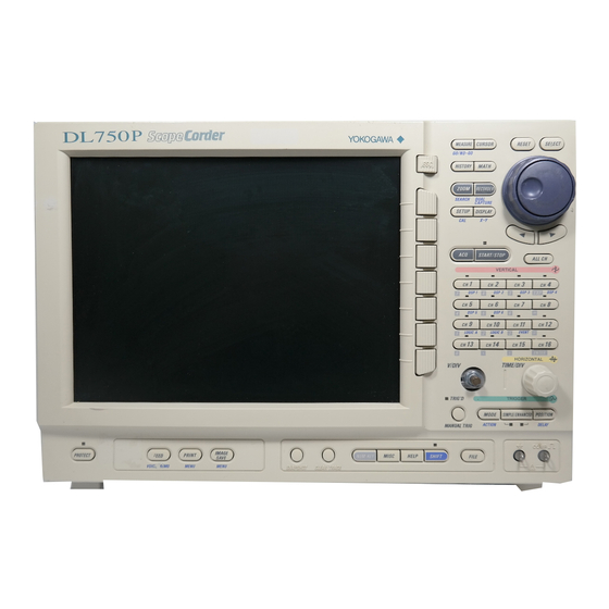
Page 5: Front Panel Controls
(search & zoom function). Section 7.6 DL750: DUAL CAPTURE key Displays a menu related to the dual capture function. Chapter 9 DL750P: RECORDER key On the DL750P Section 8.13 ESC key Displays a menu related to the recorder mode. - Page 6 Pressing the SHIFT key followed by the MODE key displays Displays a menu related to the voice memo function. a menu related to action-on-trigger or action-on-stop. Section 9.1 DL750P: FEED key On the DL750P Executes paper feeding on the DL750P TRIGGER built-in printer. FEED VOICE MEMO Section 6.19...
-
Page 7: Parts Of The Screen
Parts of the Screen Parts of the Screen Parts of the Screen This section describes the menus and symbols that appear on the DL750/DL750P screen. For details on each item, see the chapter or section in the user’s manual indicated by the mark. - Page 8 Screen When Displaying Zoom Waveforms Section 8.5, “Zooming the Waveform” in the User’s Manual Part 1 Display position of the Z1 zoom waveform on the record length T/div of the Z1 zoom waveform display Display position of the Z2 zoom waveform on the record length Z1 zoom range Z2 zoom range T/div of the normal...
-
Page 9: Basic Key & Jog Shuttle Operations
Basic Key & Jog Shuttle Operations Basic Key & Jog Shuttle Operations Basic Key & Jog Shuttle Operations This section describes basic key and jog shuttle operations used to enter settings on the DL750/DL750P. Basic Key Operations Operations When a Setup Menu Is Displayed... - Page 10 Section 4.2, “Entering Values and Strings” in the User’s Manual Part 1 By connecting a USB mouse to the USB PERIPHERAL connector on the side panel, you can use the mouse to perform the same operations as you would using the front panel keys of the DL750/DL750P. DL750/...
-
Page 11: Main Functions Of The Dl750/Dl750P
Main Functions of the DL750/DL750P Main Functions of the DL750/DL750P Main Functions of the DL750/DL750P Main Functions of the DL750/DL750P Trigger Chapter 6, “Triggering” in the User’s Manual Part 1 There are two main types of triggers: simple triggers and enhanced triggers. - Page 12 When waveforms are being measured, the waveform data stored in the acquisition memory is displayed as waveforms on the DL750/ DL750P screen. When waveforms are continuously measured, it is impossible to stop the measurement in time when an abnormal waveform appears (newer waveforms appear on the screen). Normally, past abnormal waveforms cannot be displayed. However, past waveform data stored in the acquisition memory can be displayed using the history memory function while measurement is stopped.
- Page 13 Automatically divides a periodic waveform stored to the acquisition memory into cycles, and measures the waveform parameters. Then, statistical processing is performed on the automated measurement values. The DL750/DL750P screen displays 5 statistical processing parameters (maximum (Max), minimum (Min), average (Avg), standard deviation (sdv), and the number of measured values used in the statistical processing (Cnt)) on the automated measurement parameters of the waveform.
- Page 14 Computation (Standard) & User-Defined Computation (/G2 Option) Section 10.5, “User-Defined Computation (Optional)” in the User’s Manual Part 2 The following types of computation are possible: +, –, ×, /, FFT (power spectrum), and phase shift computation (computation with the phase between channels shifted). On models with the user-defined computation function (/G2 option), up to 8 equations can be defined using abundant functions (such as trigonometric functions, differentiation, integration, square root, digital filter, and 7 types of FFT functions).
- Page 15 Chapter 9, “Recording in Recorder Mode (Realtime Recording)” in the User’s Manual Part 1 The DL750P is equipped with a recorder mode in which waveforms and numeric values can be recorded on a built-in A4-size printer. The recorder mode is set using the RECORDER key on the DL750P front panel. There are two recorder modes.
- Page 16 By connecting a earphone microphone with a PUSH switch to the DL750/DL750P, you can record a comment on the displayed DL750/DL750P, you can record your voice as a memo while waveform using your voice. When saving the screen image data, waveforms are being acquired (when in roll mode display).
-
Page 17: Operating The Dl750/Dl750P
/DL750P The operation explained in this section is used to observe a signal (probe compensation signal) that is generated by the DL750/DL750P. Therefore, there is no need to prepare a separate signal generator. Additionally, this operation guide describes an example in which waveforms are observed using the High-Speed 10 MS/s, 12-Bit Isolation Module (model: 701250, abbreviated name: HS10M12). - Page 18 Section 3.6, “Connecting Probes” and 3.7, “Compensating the Probe (Phase Correction)” in the User’s Manual Part 1 To use the DL750/DL750P in a safe manner, read the warnings given in section 3.6, “Connecting Probes” and the cautions given in section 3.7, “Compensating the Probe (Phase Correction)”...
-
Page 19: Displaying Waveforms On The Screen
The settings made using the front panel keys are reset to factory default. This operation is not necessary if you are using the DL750/ DL750P for the first time after purchase. However, we recommend that you try the operation for future reference. This initialization operation is useful when you wish to redo the settings from scratch according to the input signal. -
Page 20: Changing The Waveform Display Conditions
Changing the Waveform Display Conditions This section explains the operations used to divide the screen into windows and change settings such as the voltage sensitivity and vertical position (vertical axis) and the time axis (horizontal axis). Set the Number of Windows to Single Section 8.1, “Changing the Display Format”... - Page 21 Operating the DL750/DL750P Lower the Vertical Position for Viewing the Entire Waveform Amplitude Section 5.4, “Setting the Vertical Position of Waveforms” in the User’s Manual Part 1 Press the CH 1 key. Turn the jog shuttle counterclockwise to set Position to -2.50 div.
- Page 22 Change the Time Axis Setting from 100 ms/div to 50 µs/div Section 5.2, “Setting T/div” in the User’s Manual Part 1 The display returns from roll mode to update mode, and 5 periods of the waveform are displayed. Turn the TIME/DIV knob clockwise and set the time axis to 500 µs/div. Time axis setting of CH1 Update mode display IM 701210-07E...
-
Page 23: Changing The Trigger Setting
Operating the DL750/DL750P Changing the Trigger Setting Setting the trigger refers to the setting of the time position of the waveform to be displayed of the acquired signal waveform. The main trigger settings are indicated below. Triggers can be classified into simple triggers and enhanced triggers. For details, see page 10. - Page 24 Move the Trigger Position Left by 2 div Section 6.2, “Setting the Trigger Position” in the User’s Manual Part 1 The waveform moves to the left by 2 div showing more of the section after the trigger occurrence (post-trigger section). Press the POSITION key.
-
Page 25: Measuring Waveforms
Operating the DL750/DL750P Measuring Waveforms This section explains the operation for measuring the voltage and period of the displayed waveform using the vertical cursors (V cursors). Automated measurement of waveform parameters, computation, and other functions are also available for measuring pulse and other waveforms. -
Page 26: Zooming The Waveform Along The Time Axis
Zooming the Waveform along the Time Axis This section explains the operation for expanding along the time axis a section of the displayed waveform. Though not explained here, waveforms can also be zoomed along the voltage axis. Set the Zoom Rate Section 8.5, “Zooming the Waveform”... -
Page 27: Printing/Saving Waveforms
Section 12.2, “Printing Using the Built-in Printer” in the User’s Manual Part 2 Waveforms displayed on the screen are printed as shown. Before printing, install a roll paper in the built-in printer according to the procedures given in section 12.1 (9.1 for the DL750P) in the user’s manual. Press the PRINT key. - Page 28 Save the Waveform Data to a Specified Storage Medium Section 13.7, “Saving/Loading the Waveform Data” in the User’s Manual Part 2 Saves the data of the waveform displayed on the screen to the storage medium. When the save operation is executed, the setup data of the vertical axis, horizontal axis, and trigger of the saved waveform are also saved.
-
Page 29: Setup Menu Items
Setup Menu Items Setup Menu Items Setup Menu Items Setup Menu Items For details on each menu, see the chapter or section in the user’s manual Part 1 or Part 2 indicted by the mark. SETUP (CAL) Center position after auto setup Selects whether the center position after auto setup is set to 0 V or the offset value. -
Page 30: Ch1 To Ch16 (Logic, Event, Dsp)
CH1 to CH16 (LOGIC, EVENT, DSP) • The following figure shows the menu for the channels that have Voltage Modules (see Note on this page) installed. Section 5.1 Turn ON/OFF the channel Sections 5.4 and 5.9 Variable/Position Turn Variable ON to set the upper and lower Note limits of the vertical axis according to the Voltage Modules... - Page 31 Select whether to perform reference junction Note compensation by the internal RJC circuit Reference Junction Compensation (RJC) (ON/OFF). The DL750/DL750P normally performs reference junction compensation with the built-in RJC circuit Section 5.16 Burnout when measuring temperature with the thermocouple. Set the behavior when the thermocouple input detects a burnout.
- Page 32 CH1 to CH16 • The following figure shows the menu for the channels that have Strain Modules (see Note on this page) installed. Section 5.1 Turn ON/OFF the channel Section 5.17 Measurement range/unit Set the unit of the measurement range to the unit of strain (µSTR) or the output value of the strain gauge transducer (mV/V).
- Page 33 Gain Set the ratio of the output signal with respect Connecting Acceleration Sensors to the input signal in the range of ×0.1 to ×100. The DL750/DL750P allows built-in amplifier type (low impedance) acceleration sensors to be directly Section 5.7 Bandwidth connected to the acceleration/voltage module.
- Page 34 CH1 to CH16 • The figure below shows the menu of the channel in which the frequency module (701280 (FREQ)) is installed. Section 5.1 Turn ON/OFF the channel Sections 5.4 and 5.9 Variable/Position Turn Variable ON to set the upper and lower limits of the vertical axis according to the displayed waveform and zoom or expand the waveform vertically.
- Page 35 Setup Menu Items CH1 to CH16(LOGIC, EVENT) Turn ON/OFF logic waveforms Section 5.20 Position Set the vertical position of the waveform. Vertical zoom/expand Set the magnification when waveforms are zoomed/expanded vertically. Note Label Set labels for logic inputs A and B using up to Differences in the Bit Display Position 8 characters.
- Page 36 CH1 to CH16(DSP) Section 5.1 Turn ON/OFF the channel Note Variable/Position Sections 5.4 and 5.9 DSP Channel (/G3 Option) Turn Variable ON to set the upper and lo wer DSP (Digital Signal Processor) channels are used to limits of the v ertical axis according to the perform computations between channels and filter displayed w aveform and zoom or e xpand the computations in realtime using the output data of the...
-
Page 37: Acq
• Average Section 7.3 Acquisition mode The DL750/DL750P takes the linear or exponential Select the processing method when waveform average of the waveform data and stores the results into data is stored to the acquisition memory from the acquisition memory. -
Page 38: Simple/Enhanced
SIMPLE/ENHANCED • The following figure shows the menu that appears when the trigger type is set to simple trigger. Chapter 6 Trigger type Select simple trigger. Trigger source Select the trigger source from the input signal (CH1 to CH16, LOGIC A, or LOGIC B, DSP1 to DSP6 (/G3 option)), external input signal Note (Ext), power supply signal (Line), or time. -
Page 39: Mode (Action)
Trigger Mode during DL750P Recorder Mode If Chart Recorder mode (see page 56) is selected on the displayed waveforms are updated. DL750P, select the trigger mode from Auto, Log, Section 7.5 Single (N) count Single, and Repeat. If X-Y Recorder mode is selected, Set the number of waveform acquisitions for the trigger mode cannot be set. - Page 40 Section 6.18 Action on trigger Performing a specified action each time a trigger occurs. Note Action Types Section 6.18 Action on stop Performing a specified action each time a • Print the screen image data (PRINT) trigger occurs. Prints the screen image data to a specified printer. •...
-
Page 41: Position (Delay)
Setup Menu Items POSITION (DELAY) Section 6.2 Trigger position Set the trigger position with respect to the display record length in terms of a percentage (0 to 100%). Note To the 10% position Set the trigger position to the 10% position of the display record length. -
Page 42: Dual Capture
DUAL CAPTURE DL750 DL750P DUAL SHIFT RECORDER CAPTURE DAUL CAPTURE Section 7.6 Turn ON/OFF dual capture Time/div of the sub waveform Specify the acquisition waveform number Specify the number of the sub waveform you wish to display. Sub waveform display frame size and... -
Page 43: Display (X-Y)
Setup Menu Items DISPLAY (X-Y) Section 8.1 Display format Sets the number of divided windows for displaying waveforms. Select from Single (no divisions), Dual, Triad, Quad, Octal, and Hexadecimal. Section 8.2 Display interpolation In areas where less than 1000 points of data exist in the 10 divisions along the time axis (referred to as interpolation areas), a Note... - Page 44 • The following figure shows the menu that appears when the waveform display format is set to T-Y&X-Y. Section 8.6 Waveform display format Select from T-Y&X-Y (both normal waveforms and X-Y waveforms), X-Y (only X-Y waveforms), and T-Y (only T-Y waveforms). Note X-axis mode Select Single in which the X axis is set to a...
-
Page 45: Measure (Go/No-Go)
Setup Menu Items MEASURE (GO/NO-GO) • The following figure shows the menu when the mode is set to ON (automated measurement of waveform parameters). Turn ON/OFF the automated measurement of waveform parameters Note Section 11.6 Select ON when performing automated Voltage-Axis Parameters measurement of waveform parameters. - Page 46 • The following figure shows the menu when the mode is set to Cycle Statistics. Statistical processing mode Note Section 11.7 Select Statistics for normal statistical Statistical Processing processing, Cycle Statistics for cycle statistical Statistical processing is performed on the values processing, or History Statistics for statistical obtained by the automated measurement of waveform processing of history data.
- Page 47 Setup Menu Items • The following figure shows the menu that appears when the GO/NO-GO determination mode is set to the measured values of waveform parameters. GO/NO-GO determination mode Section 11.8 Select the measured values of waveform Note parameters (Parameter). Types of GO/NO-GO Determination Mode Determination condition This function is useful when you want to inspect signals...
-
Page 48: Cursor
CURSOR • The following figure shows the menu that appears when the cursor type is set to V cursor. Note Section 11.5 Cursor type Cursor Types Select from H cursor, V cursor, H&V cursor, • H (Horizontal) cursors marker cursor, and angle cursor. Two broken lines (H cursors) are displayed on the X- axis (horizontal axis). -
Page 49: History
Setup Menu Items HISTORY Select the displayed waveform Section 11.1 Note Specify the waveform data to be displayed Waveform Display Format from the waveform data stored in the history • One memory. Displays the waveform specified by Select Record among the waveforms in the range specified by Start Section 11.1 Waveform display format Select the display format of the waveform data... -
Page 50: Math
MATH Turn ON/OFF the computation function Chapter 10 Set computation Define the computation and set the computation target channel, scaling, unit, Note label, and ON/OFF of Math waveforms. Waveform Computation Example Number of FFT points +Computation waveform Select the number of points used in performing the FFT from 1000 (1 k), 2000 (2 k), 5000 (5 k), 10000 (10 k), 20000 (20 k), 50000 (50 k), Waveform to be... -
Page 51: Zoom (Search)
Setup Menu Items ZOOM (SEARCH) • The following figure shows the menu that appears when the display mode of zoomed waveform is set to Main&Z1&Z2. Select the display mode of zoomed Section 8.5 waveforms Select how the normal waveforms and two zoomed waveforms (Z1 and Z2) are displayed. - Page 52 ZOOM (SEARCH) • The following figure shows the menu that appears when the search type is set to Edge. Section 11.4 Select the search type Select edge search in which search is performed on the number of times the waveform goes above a specified level (rising) or the number of Note times the waveform goes below a specified...
- Page 53 Setup Menu Items ZOOM (SEARCH) • The following figure shows the menu that appears when the search type is set to Voice. Select the search type Section 11.4 Select voice search in which search is performed on the start section of the voice memo recording (rising edge of the voice bit of the event waveform).
-
Page 54: Voice Memo
1. In addition to the voice memo function, a voice comment function is available that allows voice comments to be attached to screen image data. For details on the voice comment function, see section 13.19 in the DL750/DL750P User’s Manual Part 2. -
Page 55: Print
Print destination Select the print destination of the screen image from built-in printer, USB printer, network printer, and PDF (DL750P only). Output format Select the output format from (1) normal size print, (2) fine print in which a specified range... -
Page 56: Image Save
IMAGE SAVE Note Section 13.12 Thumbnail list Example of Thumbnails of the Stored Screen Image Lists the thumbnails of the stored screen images. Section 13.11 Output format Select the storage format of the screen image data from PNG, JPEG, BMP, and PostScript. Section 13.11 Color Select the coloring used when the screen... -
Page 57: Recorder (Only Dl750P)
Then, the recording length from 20 cm, 50 cm, 1 m, 2 m, or OFF (do not shot record). DL750P enters the trigger-wait state. Acquisition Mode during Chart Recorder Mode Section 9.3 Printer output... - Page 58 RECORDER DUAL CAPTURE • The following figure shows the menu that appears only when the recorder mode is set to X-Y. Section 9.2 Recorder mode Select the recorder mode to chart, X-Y, or OFF. Section 9.7 Sample rate Select the sample rate from 5 S/s to 5 kS/s. Section 9.7 Specify the print settings Set the print format, graticule, and detailed...
-
Page 59: Misc
• Save, delete, copy waveform data, screen image data, and setup data to the FTP server on the network. Chapter 16 • Access the DL750/DL750P from an FTP client on the Network Sets TCP/IP parameters that are required when network and retrieve the files on the storage medium... - Page 60 MEMO IM 701210-07E...
- Page 61 MEMO IM 701210-07E...
Need help?
Do you have a question about the DL750P and is the answer not in the manual?
Questions and answers