Table of Contents
Advertisement
Advertisement
Table of Contents

Related Manuals for Simrad IS40


Summary of Contents for Simrad IS40
- Page 1 IS40 Display Operator Manual ENGLISH simrad-yachting.com...
- Page 3 About this manual This manual is a reference guide for operating the IS40 instrument and OP10 Autopilot controller. It assumes that all equipment is installed and ready to use. The manual assumes that the user has basic knowledge of navigation, nautical terminology and practices.
- Page 4 The software This manual is written for Simrad IS40 Release to Market 1 (RTM1). Please check website for details on the current release version. ¼ Note: The menu route shown above is an example only and may not match the software installed on your unit! ¼...
-
Page 5: Table Of Contents
Contents Operation The IS40 Display and OP10 Autopilot controller Pages Default pages Replacing a data page Changing an analog display scale Template pages Customizing a page Auto scroll Timer Alarms Setup Sources Device list Time & Date Units Display mode... - Page 6 Autopilot response Sea state filter Sailing Automatic steering Reset Maintenance General maintenance Specifications Technical specifications Dimensional drawings Display OP10 Autopilot controller Menu flow chart Contents | IS40 Operator Manual...
-
Page 7: Operation
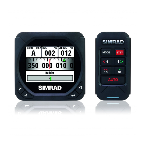
Operation The Simrad IS40 system is a networked multifunction instrument display and OP10 Autopilot controller. The display shows speed, depth, heading, position, wind and environmental data measured by sensors and other equipment connected to the system. Navigational data, engine/battery status and vessel parameters such as accumulated log and rudder angle may also be displayed. -
Page 8: Pages
¼ Note: Only seven pages will be available when in Instrument Only display mode. ¼ Note: Two or more pages need to be enabled for the page key to function. Operation | IS40 Operator Manual... -
Page 9: Default Pages
True wind angle (TWA) Basic Wind / Speed Two line data display. Apparent Wind Angle and True Wind Speed Wind angle indicator - Green arrow right = Starboard tack. Red arrow right = Port tack Beaufort scale indicator Operation | IS40 Operator Manual... - Page 10 Current depth and histogram of recorded depth data. Depth value Boat type - Sail or Motor boat image Depth graphic ¼ Note: You can adjust the time period scale via the up & down keys. Operation | IS40 Operator Manual...
- Page 11 GPS. Highway The Highway page presents the following information: Waypoint name Estimated time of arrival (ETA) Next waypoint Highway graphic Bearing to waypoint (BTW) Cross track error (XTE) Distance to waypoint (DTW) Operation | IS40 Operator Manual...
- Page 12 Current Target Standby Heading Auto Heading Set heading Non FollowUp Heading Rudder Angle Navigation Heading Set heading NoDrift Heading Set heading True Wind Angle (TWA) Wind Set Wind Angle Apparent Wind Angle (AWA) 10 | Operation | IS40 Operator Manual...
-
Page 13: Replacing A Data Page
To make a data page available via the page key you will need to first ensure it has been selected as one of the eight available pages. Once the page has been selected as one of the eight data pages you can enable it as shown below: | 11 Operation | IS40 Operator Manual... -
Page 14: Changing An Analog Display Scale
0° - 180° 0° - 50° 10° increments 5° increments Rudder angle & Heel angle analog displays The rudder angle and heel angle analog displays have an inverted scale with zero at the bottom. 12 | Operation | IS40 Operator Manual... -
Page 15: Template Pages
Displays data as a histogram with a data value Histogram shown above Analog Displays data as an analog display Full Screen Analog Displays data as a full screen analog display Highway Highway graphic with three pieces of data below | 13 Operation | IS40 Operator Manual... -
Page 16: Customizing A Page
If a data type is selected, but there is no sensor on the network providing the information, there will be no data reading on the display. Instead there will be dashes. ¼ Note: Press the page key at anytime to return to the template. 14 | Operation | IS40 Operator Manual... -
Page 17: Auto Scroll
To stop auto scroll, deselect Start auto scroll. ¼ Note: You can set the time interval of the screen transition from this menu, by selecting Scroll time and modifying the interval time. | 15 Operation | IS40 Operator Manual... -
Page 18: Timer
Once a start value has been set, to start the timer, highlight Start timer and press ‘Enter’ . The display will turn to the timer page and begin counting accordingly. To stop the timer from counting, select Timer Setup, highlight Stop Timer and press ‘Enter’ . 16 | Operation | IS40 Operator Manual... -
Page 19: Log
¼ Note: The Log and Date cannot be reset. The date is taken from the global time and date settings. The time can be set to correspond with your global position. | 17 Operation | IS40 Operator Manual... -
Page 20: Alarms
Enabled and select OK once complete. The alarm can be disabled by deselecting Enabled. Below is an example of how to set a shallow water alarm. Select Enabled and set the desired depth. 18 | Operation | IS40 Operator Manual... - Page 21 For True Wind Speed (TWS), and deep and shallow depth alarms a red warning zone will be visible on the analog display to give you a visual indication of alarm zones. Shallow depth alarm Deep water alarm | 19 Operation | IS40 Operator Manual...
- Page 22 RF must be calibrated Single ¼ Note: Alarm type. Single = Single sound alarm, Cont’ = Continuous sound alarm. Both types of alarm will have a notification appear on the display until the alarm is acknowledged. 20 | Operation | IS40 Operator Manual...
-
Page 23: Setup
If more than one source is available for an item, the preferred source may be selected manually. As an example, the following illustrations show how the compass source is changed. Select the preferred data source. The selected source will be indicated by a tick in the check box. | 21 Setup | IS40 Operator Manual... -
Page 24: Device List
For accurate speed and log readings, it is essential that the paddlewheel is calibrated. Boat speed values can be shown in knots, kph or mph. Your preferred unit of measurement can be set in the Units page of the setup menu. 22 | Setup | IS40 Operator Manual... - Page 25 This facility enables the user to calibrate the log accurately and simply. Calculations are performed by the display that works out the boat speed over a known distance. To calibrate the boat speed via a distance reference you will need to complete consecutive | 23 Setup | IS40 Operator Manual...
- Page 26 After the last run is completed and OK has been selected, a pop-up warning will ask you if you wish to replace the current calibration with the new one. Select Yes to complete. 24 | Setup | IS40 Operator Manual...
- Page 27 If a suitable temperature sensor is fitted, the system will monitor the current sea temperature. The offset value to be entered should adjust the temperature reading from the sensor to match a calibrated thermometer when submersed in the water | 25 Setup | IS40 Operator Manual...
- Page 28 GPS. COG will be displayed as heading and used in the calculation of true wind direction. ¼ Note: The autopilot cannot be operated using COG as the heading source. COG cannot be calculated when stationary. 26 | Setup | IS40 Operator Manual...
-
Page 29: Time & Date
If magnetic variation is not available via a GPS an offset can be entered manually. See Magnetic variation for more information, page 30. The same applies if the user wants to read magnetic heading, but only receives true heading from the compass. | 27 Setup | IS40 Operator Manual... -
Page 30: Display Mode
Default setting is Network. Night mode Change the display to Night Mode color pallet. All displays in the selected Lighting Zone will also change to Night Mode. Lighting level Adjust the backlight level from 1-10. 28 | Setup | IS40 Operator Manual... -
Page 31: Show Graphics
The damping rate effects the frequency that the sensor data is updated on the display, the greater the damping value the smoother the number change will be but the slower the response will be to data change. | 29 Setup | IS40 Operator Manual... -
Page 32: Decimal Places
From the system menu there are several options to reset the system, place the display into simulator and get the current software information. Reset options There are a variety of reset options available from the system menu. 30 | Setup | IS40 Operator Manual... - Page 33 The autopilot will need to be commissioned before use. Simulator Simulator mode sends simulated data to the display. Warning: It is not advisable to enter Simulator Mode when using your instrument system as a navigation aid. | 31 Setup | IS40 Operator Manual...
-
Page 34: Diagnostics
We recommend that you use this diagnostic tool as a basic overview of the network status. For more detailed information it is suggested that you check the individual source information via the device list. 32 | Setup | IS40 Operator Manual... -
Page 35: Autopilot
Do not place any magnetic material or equipment near the heading sensor used by the autopilot system Verify at regular intervals the course and position of the vessel Always switch to Standby mode and reduce speed in due time to avoid hazardous situations | 33 Autopilot | IS40 Operator Manual... -
Page 36: Op10 Autopilot Controller
Right 10º: Adjust the set course or wind angle 10 degree / steer to Starboard in NFU mode. When pressed in Standby mode this will enter the autopilot into NFU mode. Engage the autopilot / Acknowledge tack/gybe or navigation course change. 34 | Autopilot| IS40 Operator Manual... -
Page 37: Turning The Autopilot On / Off
Steers the boat to a specific Heading, Speed, & Hold Navigation waypoint location, or along Position, Waypoint, 3 sec + a route Route information Steer the boat manually Non Follow Up using the OP10 Autopilot controller | 35 Autopilot | IS40 Operator Manual... -
Page 38: Autopilot Symbols
Press the ‘Auto’ key to enter Auto mode or accept a tack/gybe or navigation course change. Press the ‘STBY’ key to place the autopilot into Standby mode. Boat Type: 3 SEC Boat Type: ¼ Note: The display will not update until the autopilot engages the new selected mode. 36 | Autopilot| IS40 Operator Manual... -
Page 39: Standby Mode (Manual Helm Steering)
To select Wind mode set the autopilot to Auto mode then press the ‘Mode’ key. The Wind mode symbol (W) is shown on the display and Wind mode is engaged | 37 Autopilot | IS40 Operator Manual... - Page 40 The rate of turn during the tack/gybe is set by the ‘Tack/Gybe Time’ parameter in the Setup/ Sailing menu. The tack/gybe time is also related to the speed of the boat to prevent excessive loss of speed during a tack. 38 | Autopilot| IS40 Operator Manual...
-
Page 41: Nodrift Mode
The autopilot will keep the boat on that course until a new mode is selected. Prior to entering NoDrift mode the autopilot system should be operating in Auto, with valid input from the GPS receiver. | 39 Autopilot | IS40 Operator Manual... -
Page 42: Navigation Mode (Steer To Waypoint)
The Navigation display presents the following information: Response mode Autopilot mode: N = Navigation mode Compass graphic (Heading) Rudder angle graphic Bearing to waypoint Heading Set heading indicator - Green = Starboard / Red = Port 40 | Autopilot| IS40 Operator Manual... - Page 43 Navigation mode prompt. When you arrive at the waypoint, the system will output an audible warning, display an alert screen with the new course information, and automatically change course onto the new leg. | 41 Autopilot | IS40 Operator Manual...
-
Page 44: Non Follow Up Mode
Heading Using the Autopilot in an EVC System When the IS40/OP10 is connected to an EVC system via the SG05, you can take manual control of the steering irrespective of the autopilot mode. The mode indicator on the autopilot pop-up will be replaced by a dash to indicate EVC override. -
Page 45: Autopilot Settings
Setup. Commissioning Before the autopilot can be used, you must first commission it and complete all of the dockside procedures before it is operational. | 43 Autopilot Setup | IS40 Operator Manual... -
Page 46: Dockside
The Max starboard angle is the angle read by the rudder feedback unit before any adjustment is made. If the actual rudder angle is different from the angle displayed, correct the reading with the Up/Down keys. Confirm Rudder feedback calibration to starboard by selecting Next. 44 | Autopilot Setup | IS40 Operator Manual... -
Page 47: Virtual Rudder Feedback
Unless impractical or impossible, a rudder feedback unit should be installed. VRF Calibration / Rudder test To perform the Virtual Feedback rudder test you must be able to view the movement of the engines/drives (“rudder”). | 45 Autopilot Setup | IS40 Operator Manual... -
Page 48: Rudder Drive
Ensure that the rudder information is set correctly before you continue with the Dockside commissioning. Drive voltage (V) Sets the drive voltage to the type installed on the vessel 12 or 24 V. 46 | Autopilot Setup | IS40 Operator Manual... -
Page 49: Sea Trial
If the boat is a sailboat use the Wind mode and engage the autopilot at different wind angles. If the rudder response feels aggressive during the sea trial, you may want to reduce the | 47 Autopilot Setup | IS40 Operator Manual... - Page 50 (i.e. if cruising speed is 10 knots, perform the Autotune at about 5 knots). Select Autotune to begin the tuning process. Select yes to confirm Autotune. 48 | Autopilot Setup | IS40 Operator Manual...
-
Page 51: Autopilot Response
Auto is automatically set by speed input Hi or Lo must be set manually when there is no speed input The sub-headline in the display shows the active parameter set and how it is selected. | 49 Autopilot Setup | IS40 Operator Manual... -
Page 52: Sea State Filter
A turn performed without shifting wind side, will also be made at a controlled turn rate. Range Change per step Default Units 2 - 50 Second 50 | Autopilot Setup | IS40 Operator Manual... -
Page 53: Automatic Steering
These steering parameters can be changed if needed to improve sailing performance. From this menu you can set the Transition speed, high and low boat speed parameters to account for changes in boat speed, rudder angle, wind and compass settings. | 51 Autopilot Setup | IS40 Operator Manual... - Page 54 Counter Rudder is the parameter that counteracts the effect of the boat’s turn rate and inertia. For a short time period it is superimposed on the proportional rudder response caused by the 52 | Autopilot Setup | IS40 Operator Manual...
- Page 55 Turning the Minimum Rudder function on, may improve the course keeping performance on some boats, but will increase the rudder activity. Range Change per step Default Units Off - 5 Off º | 53 Autopilot Setup | IS40 Operator Manual...
-
Page 56: Reset
Units 10 - 30 º Reset Resets the autopilot to factory settings. Warning: all previous Autopilot settings will be lost! Before engaging the Autopilot, the commissioning and calibration process must be completed. 54 | Autopilot Setup | IS40 Operator Manual... -
Page 57: Maintenance
Software upgrade To find out the latest version of software available for your display, go to the Simrad website www.simrad-yachting.com To verify what software you are currently running, go to the software information page on your display. - Page 58 56 | Maintenance | IS40 Operator Manual...
-
Page 59: Specifications
Technical specifications Declarations and conformance This equipment is intended for use in international waters as well as coastal sea areas ad- ministered by countries of the E.U. and E.E.A. For more information refer to the separate IS40 Installation manual. Display Weight 0.28 kg (0.6 lbs) -
Page 60: Dimensional Drawings
Dimensional drawings Display 118 mm (4.65") 17 mm (0.67") 18.9 mm (0.74") OP10 Autopilot controller 18.0 mm (0.71") 60.0 mm (2.36") 88.0 mm (3.46") 15.3 mm (0.60") 58 | Specifications | IS40 Operator Manual... -
Page 61: Menu Flow Chart
SOG reference Distance reference [List] Time & Date Date format Time format Local time Units [List] Language [List] Display mode Instruments only Pilot only Pilot when engaged Boat type Power boat Sail boat | 59 Specifications | IS40 Operator Manual... - Page 62 Counter rudder Auto trim Rate limit Rudder Counter rudder Auto trim Rate limit Minimum rudder Min Wind - Starboard Min Wind - Port Nav change limit Installation Commissioning Dockside Sea trial Rudder drive Reset 60 | Specifications | IS40 Operator Manual...
- Page 64 N2584...
Need help?
Do you have a question about the IS40 and is the answer not in the manual?
Questions and answers