Table of Contents
Advertisement
Quick Links
Download this manual
See also:
Manual
Advertisement
Table of Contents

Related Manuals for Simrad IS20 Combi


Summary of Contents for Simrad IS20 Combi
- Page 1 Manual Simrad IS20 Combi Instrument English Sw. 1.2 www.simrad-yachting.com A brand by Navico - Leader in Marine Electronics...
- Page 2 As we are continuously improving our products we retain the right to make changes to the product and the documentation at any time. Updated manuals are available from our website www.simrad-yachting.com, and are free to download. © Copyright 2008 by Navico Holding AS.
-
Page 3: About This Manual
About this manual This manual is a reference guide for installing and operating the Simrad IS20 Combi instrument. The manual does not include operator or installation procedures for sensors that can be connected to the system. In this manual, names of menu commands, dialog box text and keys are written in boldface (e.g. -
Page 4: Table Of Contents
4 Changing the default settings ....23 General ............. 23 Setting the damping factors ......23 Alarm setup ..........24 Updating the data sources ......26 Changing the display settings ....... 28 Language selection ........29 IS20 Combi instrument | 3... - Page 5 First time start-up ........47 Calibration ..........48 SimNet groups ..........52 8 Maintenance ..........53 General maintenance ........53 Service information ........53 Resetting the instrument system ....54 Displaying instrument information ....55 4 | IS20 Combi instrument...
- Page 6 9 Spare parts ..........57 Spares and auxiliaries ........57 SimNet cables and accessories ..... 58 10 Specifications ......... 59 Technical specifications ........ 59 Dimensional drawings ........60 Menu flow chart .......... 61 IS20 Combi instrument | 5...
- Page 7 Blank page 6 | IS20 Combi instrument...
-
Page 8: Introduction
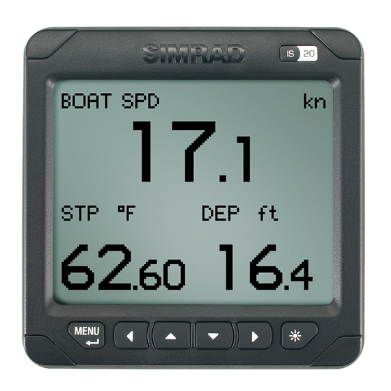
1 Introduction General information The IS20 Combi is an instrument that displays speed, depth and temperature data measured by sensors con- nected to the system. Accumulated log and trip log as well as race log and timer are implemented. Instrument layout The IS20 has a 130 * 104 pixels LCD. -
Page 9: Screen Symbols
Softkeys When the basic operation of the keys is changed, soft key symbols will be displayed right above the keys to indicate the alternate function. The softkey symbols are illustrative, and they are de- scribed under the functions as these appear in this manual. - Page 10 IS20 Combi, Basic system IS20 Combi, Basic system with 2 sensors Introduction | 9...
- Page 11 IS20 Expanded system 10 | Introduction...
-
Page 12: Operation
2 Operation It is required to read and understand the content in this chapter. The remaining descriptions and illustrations in this manual assumes that the user is familiar with how to operate keys and how to navigate in the menus! Turning the IS20 on IS20 has no power key, and will be running as long as power is connected. -
Page 13: Backlighting
Backlighting The display backlight may be adjusted at any time. Press the light key The Light level overlay window will be displayed on top of the current view. Press one of the keys as described below to change the display backlight: Light key to increase the light level by one step Up/Down softkeys to increase/decrease... -
Page 14: Scrolling Through Data Pages
Scrolling through data pages The IS20 Combi is pre-configured with 4 instrument pages. The instrument will scroll through the pages by using the Up and Down keys . Default page at first time turn-on Operation... -
Page 15: Operating The Menu System
Operating the menu system All functions and settings in the IS20 are available from the menu system, activated by pressing the Menu/Enter key. The main menu items give further access to sub menus and various settings. The set values are usually presented in the window’s right column, but could also be listed in an overlay window. - Page 16 When the basic operation of a key is changed, a softkey symbol will be displayed right above the key to indicate the alternate function. Menu illustrations In this manual, the first steps in a menu operation are illustrated by overlapping menu windows.
-
Page 17: Locking And Unlocking The Keys
Locking and unlocking the keys The IS20 keys may be locked to prevent any unintended operation. The key lock function is enabled by pressing the Menu/ Enter and the Light keys simultaneously. A locked instrument has a padlock symbol in the upper left corner. -
Page 18: The Log/Timer Functions
3 The log/timer functions The timer function The timer function is used to measure time and distance after a race start. When a timer page is displayed, basic key operation is replaced by functions indicated by softkeys. The timer is by default shared between interconnected SimNet units, and all timer values will be identical. -
Page 19: Starting The Race Timer
Starting the race timer The race timer will continue to run until the Stop softkey is pressed even if the race timer page is replaced by another page! When the counter turns zero, the race log starts to log the distance, the Synchronize softkey is removed and the timer function will work as a race timer! - Page 20 Stopping and restarting the timer Stop the timer by pressing the Stop softkey. The timer will stop counting, and the softkeys will change status Restart the race timer from the stopped time by pressing the Start softkey. The race timer and race log can be stopped when counting down or counting up! Resetting the timer A stopped or paused timer is reset to the pre-set...
-
Page 21: Trip Logging
Freezing the display The timer display may be frozen at any time while the timer is running. When the display is frozen, the timer remains counting in the background. Freeze the timer display by pressing the Freeze softkey. The Freeze softkey will appear as depressed Re-press the Freeze softkey to return to the countdown view. -
Page 22: Speed Logging
Speed logging The speed log display shows: Current speed Max and average speed since the speed log was reset Resetting the speed log The speed log will automatically reset when the race timer function is active and turns zero. The speed calculation is manually reset to zero by pressing the Reset softkey. - Page 23 Blank page The log/timer functions...
-
Page 24: Changing The Default Settings
4 Changing the default settings General The factory default settings may all be changed from the User setup command in the Main menu. Updating the settings will affect all instruments in the SimNet group. Refer to SimNet group function, page Setting the damping factors The damping factors determine how fast the display will respond to changes. -
Page 25: Alarm Setup
Alarm setup The IS20 may be set up to sound an alarm if vessel or environmental parameters exceeds preferred values. The alarm monitoring is disabled by setting the value to Off. Boat speed alarm Used to give alarm if the boat speed goes beyond a selected value. - Page 26 Depth alarm The depth alarm can be set up for deep and shallow water limits. An anchor alarm can be activated to warn if the boat is drifting. The alarm will sound when during a 40 seconds time period there is a change in depth of 2-3 meters (6–10 ft).
-
Page 27: Updating The Data Sources
Updating the data sources A data source can be a sensor or a device connected to SimNet, providing information and commands to other SimNet devices. The data sources are normally configured at first time turn on. It should only be necessary to update this data if a new source is added, if a source is missing (sensor failure), or if a source has been switched off/on. - Page 28 Manual source selection If more than one source is available for each item, the preferred source may be selected manually. As an example, the following illustrations show how the compass source is changed. The position source provides Speed Over Ground (SOG). Select the preferred data source and confirm with the OK softkey.
-
Page 29: Changing The Display Settings
Changing the display settings The display is controlled by two user profiles that can be individually adjusted. The profiles are Day profile and Night profile. The profiles can be optimized for readability under different light conditions, and you can quickly switch between the two using the Light key. -
Page 30: Language Selection
Language selection The language is usually selected when the instrument is turned on for the first time. Refer to First time start- up, page 47. It is, however, possible to change the language at any time. The following languages may be selected: Deutch (German) English (English) Español (Spanish) -
Page 31: Changing The Units Of Measure
Changing the units of measure Parameter Options Default value Boat speed - kn - km/h - mph Distance - nm - mi - km Depth - ft Temperature - °C °F - °F Changing the SimNet group setup The SimNet groups are normally configured during installation, but may be changed at any time. - Page 32 Alarm Simrad, None, 1-6 Simrad Power save Simrad, None, 1-6 None Simrad: Default group for IS20 None: Not assigned to a group 1–6: Group numbers The figures on next page illustrates how the instruments on a flybridge and in a cockpit are assigned to separate language, damping and display groups, and how this affects the setup for the different instruments.
- Page 33 FLYBRIDGE LANGUAGE = NONE BACKLIGHT = 1 DAMPING = 1 COCKPIT BACKLIGHT = 2 Changing the default settings...
-
Page 34: Is20 Alarm System
5 IS20 Alarm system Alarm indication The alarm system in IS20 Combi is activated if any alarm settings are exceeded. Refer to Alarm setup, page 24. When an alarm is notified, the alarm will be indicated with an alarm text and with an audible alarm. -
Page 35: Acknowledging An Alarm
Acknowledging an alarm An alarm is acknowledged by pressing any key. This will remove the alarm notification (text, light and sound) from all units that belongs to the same alarm group. Refer to SimNet group function, page 30. A reminder will reappear at given intervals for as long as the alarm condition exists. - Page 36 Alarm ID Alarm Shallow water Deep water Anchor alarm Wind shift True wind speed too high True wind speed too low Boat speed too low Voltage too high Voltage too low Depth data missing Wind data missing Nav data missing Compass data missing Off course Rudder data missing (RF25)
- Page 37 Blank page IS20 Alarm system...
-
Page 38: Installation
6 Installation Location of the unit The IS20 should be mounted with special regard to the unit’s environmental protection, temperature range and cable length. Refer to page 59. Avoid mounting the control unit(s) where it is easily exposed to sunlight, as this may shorten the lifetime of the display. -
Page 39: Bracket Mounting
Bracket mounting An optional bracket is available for the IS20. The illustration below shows the mounting details for the bracket. Installation... -
Page 40: Cable Connection
Cable connection The IS20 Combi may be connected to SimNet network using SimNet cables. SimNet The SimNet cable system with very small plugs in both ends makes it easy to run the cables. Only 10 mm (3/8”) holes are required through panels and bulkheads. - Page 41 41, 42 and 43 SimNet must be properly terminated, i.e. unless it is a small system (see the figure on page 41) there must be terminations at each end of the Simrad backbone The SimNet network has to be terminated according to the number and type of products connected.
- Page 42 SimNet network, small system Installation...
- Page 43 SimNet network, medium system Installation...
- Page 44 SimNet network, expanded system Installation...
- Page 45 Maximum total length of SimNet cables is 150 m (500 ft.) Drop cables must not exceed 6 m (19 ft) of length and the total length of drop cables must not exceed 60 m (200 ft). Equipment should not be daisy-chained in a drop cable.
-
Page 46: Demo Mode
Demo mode The IS20 includes a demo mode, useful for demonstrations and on show. Active demo mode is indicated with flashing DEMO text in the upper right corner of the page. The demo indication will flash more frequently on the demo source than on units that are reading the demo values. - Page 47 Blank page Installation...
-
Page 48: Configuration
7 Configuration First time start-up When the IS20 is powered on for the first time, the instrument will run through an automatic start-up sequence, presenting: Product name, serial number, software version, release date Language selection Automatic data source selection Press the Menu/Enter key when the start-up procedure is completed. -
Page 49: Calibration
Calibration After installation, certain functions in the system must be calibrated to adapt to the physical position and type of sensors installed. All calibration is initiated from the CALIBRATION sub menu. Boat speed The hull shape or the location of the speed sensor may cause incorrect speed readings, and calibration is required to ensure that correct speed and log readings are displayed. - Page 50 Calibrate by speed over ground With a GPS connected to the system, the speed may be automatically set identical to the speed over ground value. This adjustment should be made in calm sea with no effect from wind or tidal current. Bring the boat up to cruising speed (above 5 knots) Select Calibrate w/SOG and press the Menu/...
- Page 51 Depth The default value for the depth offset is 0.0, which indicates the displayed depth from the transducer to the seabed (b). Refer to the illustration on the next page. The value should be increased or decreased, depending on whether the depth reading should be from the water line or from the keel, respectively: A negative offset equal to the vertical distance from the transducer to the keel will display the...
- Page 52 The symbol in front of the depth reading will change to indicate that the depth is measured from: the keel the water line Range Change per step Default value Units -10 - +10 m, ft Configuration...
-
Page 53: Simnet Groups
SimNet groups The SimNet group function is used to globally control parameter settings in groups of units. The function is used on larger vessels where several units are connected via the SimNet network. By assigning several units to the same group, a parameter update on one unit will have the same effect on the rest of the group members. -
Page 54: Maintenance
8 Maintenance General maintenance The IS20 instruments are “repair by replacement” units, and the operator is therefore required to perform only a very limited amount of preventive maintenance. If the unit requires any form of cleaning, use fresh water and a mild soap solution (not a detergent). It is important to avoid using chemical cleaners and hydrocarbons such as diesel, petrol etc. -
Page 55: Resetting The Instrument System
System data The System data screen provides status information about the different NMEA messages used by the system. Resetting the instrument system The reset options will reset the instrument to default settings. The Installation and Setup procedures must be repeated after a reset has been performed! Two different reset options are available: Local reset: Resets the selected instrument... -
Page 56: Displaying Instrument Information
Displaying instrument information By selecting the About IS20 menu item, an information window will display instrument model, software version number (1.0.), software release (02) and date of release. The shown readout is only an example! Maintenance | 55... - Page 57 Blank page 56 | Maintenance...
-
Page 58: Spare Parts
9 Spare parts Spares and auxiliaries Part no. Description 22098784 IS20 Graphic instrument head IS20 mounting kit including: - 4 screws 22096630 - 6 corners - 1 SimNet blocking plug 22096515 IS20 Weather cover 22096820 IS20 Mounting bracket 24006355 SimNet blocking plug 22098495 NMEA0183 Interface cable 2.5 m (8’) Spare parts | 57... -
Page 59: Simnet Cables And Accessories
SimNet cables and accessories Art. no. Description 24005829 0.3 m (1’) SimNet cable (SDC:0.3M) 24005837 2 m (6.6’) SimNet cable (SDC:02M) 24005845 5 m (16.6’) SimNet cable (SDC:05M) 24005852 10 m (33’) SimNet cable (SDC:10M) 24005860 SimNet T-joiner (SDJ) (3p) 24006298 SimNet Multijoiner (7p) 24006306... -
Page 60: Specifications
10 Specifications Technical specifications Weight: ............0.3 kg (1.1 lbs) Power consumption: ............. 1.3 W SimNet Network load (NL) ..........2 NL Color: ................Black Display: Type: .........Backlit LCD matrix display Resolution: ..........130 x 104 pixels Illumination (Red or white): ....Adjustable in 10 steps Environmental protection: Front: .............. -
Page 61: Dimensional Drawings
Dimensional drawings 60 | Specifications... -
Page 62: Menu Flow Chart
Menu flow chart Specifications | 61...
Need help?
Do you have a question about the IS20 Combi and is the answer not in the manual?
Questions and answers