
Subscribe to Our Youtube Channel
Related Manuals for Sindoh DP201 Series


Summary of Contents for Sindoh DP201 Series
- Page 1 DP201 Series USER MANUAL Read the User Manual before operating the product, and keep the manual at a convenient place near the product. 3dprinter.sindoh.com...
-
Page 2: Safety Instructions
Safety Instructions Be sure to observe the followIng instructions when using the device. Warning: Failure to observe the instructions may lead to death or serious injury. Directly plug the power cord in the receptacle on the wall. Do not use extension cord. If the power cable or plug is worn or damaged, pull out the power plug. - Page 3 Before use Firstly we at Sindoh truly thank you for your purchase of our product. In this user manual, there will be detailed descriptions of the correct use of device and the simple preparations of the device, maintaining the optimal state of the product at all times and contributing to the rationalization and efficiency of the office work of your company.
-
Page 4: Table Of Contents
Contents Before using the Machine Preface -------------------------------------------------------------------------------------------------------------------------- 1 How to Read This Manual ------------------------------------------------------------------------------------------------ 2 2.1 Symbols ------------------------------------------------------------------------------------------------------------------------ 2 Safety Information ---------------------------------------------------------------------------------------------------------- 3 Precautions ------------------------------------------------------------------------------------------------------------------- 5 4-1 Installation ---------------------------------------------------------------------------------------------------------------------- 5 4-2 Moving the Machine ---------------------------------------------------------------------------------------------------------- 6 Consumables Handling --------------------------------------------------------------------------------------------------- 7 Instructions for Use -------------------------------------------------------------------------------------------------------- 8 Ventilation --------------------------------------------------------------------------------------------------------------------- 9 Notices ----------------------------------------------------------------------------------------------------------------------- 10... - Page 5 View Mode Selection Button ------------------------------------------------------------------------------------------1-14 Model Maneuvering ------------------------------------------------------------------------------------------------------1-15 Adjusting Model Size ----------------------------------------------------------------------------------------------------1-16 Model Rotation ------------------------------------------------------------------------------------------------------------1-16 Print ------------------------------------------------------------------------------------------------------------------------1-16 Basic Menu Bar -----------------------------------------------------------------------------------------------------------1-16 5.3 Printing (basic functions) -----------------------------------------------------------------------------------------------1-21 Loading 3D Model Files ------------------------------------------------------------------------------------------------1-21 Basic Parameter Setting ------------------------------------------------------------------------------------------------1-21 Slicing -----------------------------------------------------------------------------------------------------------------------1-22 Print ------------------------------------------------------------------------------------------------------------------------1-23 5.4 Advanced Features ------------------------------------------------------------------------------------------------------1-23 Support Edit Function ---------------------------------------------------------------------------------------------------1-23 3D Model Analysis Function -------------------------------------------------------------------------------------------1-27 Function to Calculate Optimal Printing Direction -----------------------------------------------------------------1-29...
- Page 6 LANGUAGE ---------------------------------------------------------------------------------------------------------------2-36 E-MAIL ----------------------------------------------------------------------------------------------------------------------2-38 UNIT ------------------------------------------------------------------------------------------------------------------------2-42 TIME SETTING -----------------------------------------------------------------------------------------------------------2-43 TIME ZONE ---------------------------------------------------------------------------------------------------------------2-45 WEB ------------------------------------------------------------------------------------------------------------------------2-46 SOFTWARE UPDATE --------------------------------------------------------------------------------------------------2-48 1.3 Information -----------------------------------------------------------------------------------------------------------------2-50 Chapter 3 Printing Printing ---------------------------------------------------------------------------------------------------------------------- 3-2 1.1 Printing with USB Flash Drive ------------------------------------------------------------------------------------------ 3-2 1.2 Printing Via PC ------------------------------------------------------------------------------------------------------------- 3-6 1.3 Next print job -------------------------------------------------------------------------------------------------------------- 3-6 Chapter 4 Printable Verification Printable Verification ---------------------------------------------------------------------------------------------------- 4-2...
- Page 7 Methods of Exchanging consumables -------------------------------------------------------------------------- 5-8 4.1 Exchanging Bed ----------------------------------------------------------------------------------------------------------- 5-8 Removing Flexible Bed -------------------------------------------------------------------------------------------------- 5-8 Installing Flexible Bed ---------------------------------------------------------------------------------------------------- 5-8 4.2 Exchanging Cartridge --------------------------------------------------------------------------------------------------- 5-8 4.3 Exchanging Nozzle ------------------------------------------------------------------------------------------------------- 5-9 Methods of Detaching Nozzle ------------------------------------------------------------------------------------------ 5-9 Assembling the Nozzle -------------------------------------------------------------------------------------------------5-11 Chapter 6 Appendix Consumables Category (Material, Color) ----------------------------------------------------------------------- 6-2 ⅳ...
-
Page 9: Before Using The Machine
- The content of the User Manual is subject to change without any prior notification. Sindoh shall not be responsible for any consequent damages or losses, indirect, special, contingent handling or operations of the machine in whatsoever. -
Page 10: How To Read This Manual
Before using the Machine How to Read This Manual Symbols This manual uses the following symbols and meanings. - Indicates importance safety notes. Ignoring these notes could result in serious injury or death. Be sure to read these notes carefully for your safe operations of the machine. - Indicates important safety notes. -
Page 11: Safety Information
Before using the Machine Safety Information Plug the power cord into a properly grounded outlet which is near and quickly accessible from the machine. Do not use or place the machine in wet or humid environment. Hot Surface - The inside of the machine may be hot. To reduce the risk of injury from a hot component, allow the surface to cool before touching it. - Page 12 Before using the Machine Injuries - To prevent personal injuries or damages to the machine, you need to follow the below instructions before moving the machine. Do not open the front and top door during machine operation. When the power is on, do not let any of your body touch the machine except the bed.
-
Page 13: Precautions
Before using the Machine Precautions Please comply with the following instructions and the “Safety Information” provided with the purchase of this product. Installation - Install the machine in a well ventilated area. Odor may be emitted during machine operation. It should not be harmful; however, if the area of where the machine is located is not ventilated, make sure to ventilate the area appropriately time to time. -
Page 14: Moving The Machine
Before using the Machine Moving the Machine - Before moving the machine, be sure to unplug the power cord from the outlet. When moving the printer, it is recommended that two people lift and move the printer for safety. - Hold the bottom handles of the machine when moving it. Bend your knees enough to protect your spine when lifting the machine. -
Page 15: Consumables Handling
Before using the Machine Consumables Handling - Do not burn the Cartridge unit or filament. It may be a cause of big fire or burn by ignition. - Keep them out of the reach of children. - If skin irritation occurs after touching the filament, please see a doctor. - Do not keep the cartridge unit in a place. -
Page 16: Instructions For Use
Before using the Machine Instructions for Use - The nozzle inside the machine is very hot during machine operation. Please be cautious not to touch the nozzle during removal of the printed objected or during inspection of the machine inside. It may become the cuase of injuries or burns. - Never make the Machine operated in the way of not being specified in this USER MANUAL. -
Page 17: Ventilation
Before using the Machine Ventilation - Use the machine in a place with good ventilation. If the machine is used in a place without good ventilation, this may be harmful for your health. Ventilate it at regular basis. - Do not block vents. Inappropriate cooling may lead to high temperatures inside the machine, - In general, a new machine may produce small amount of gaseous components, so provide good ventilation for the first period of use. -
Page 18: Notices
Before using the Machine Notices Noise Emission Level The following are measured in accordance of ISO 7779 and reported to meet ISO 9296. Some modes may not be available in your purchased products. Average Sound Pressure at 1 Meter Away Printing 53dBA(Normal Print Condition - Printing speed 40 mm/s, Travel speed 150 mm/s) Standby... - Page 19 Before using the Machine Wireless LAN Specifications The competent wireless device may be affected by electromagnetic interference so it should not be used for life saving services. WLAN Notice Exposure to radio frequency radiation The following notice is applicable if your printer has a wireless network card installed. The radiated output power of this device is far below the FCC radio frequency exposure limits.
- Page 20 Before using the Machine...
-
Page 21: Disposal Of Used Battery
Before using the Machine Disposal of Used Battery Control board consists of Lithium Batteries which are located within the machine. Please discard used batteries following the environmentally friendly procedure stated on the manufacturer guidelines. To replace batteries, please contact manufacturer service engineer. - Page 22 Before using the Machine 10. Wifi Module Disclaimer This Product contains the Wi-Fi module that is only compatible with below Sindoh models DP201, DP202 Wifi module is here(inside). Precautions This Wifi module can cause radio interference, therefore it should not be used for any purposes related to human lives.
- Page 23 Before using the Machine Precautions IEEE 802.11b : 2400MHz ~ 2484MHz IEEE 802.11g : 2400MHz ~ 2484MHz Frequency IEEE 802.11n(20MHz) : 2400MHz ~ 2483MHz IEEE 802.11n(40MHz) : 2400MHz ~ 2483MHz Antenna Power Density IEEE 802.11b : 10mW(10dbm)/MHz IEEE 802.11g : 10mW(10dbm)/MHz IEEE 802.11n(20MHz) : 10mW(10dbm)/MHz IEEE 802.11n(40MHz) : 10mW(10dbm)/MHz No.
-
Page 24: 11. Usb Memory Disclaimer
Before using the Machine 11. USB Memory Disclaimer FCC COMPLIANCE STATEMENT This device complies with part 15 of the FCC Rules. Operation is subject to the following two conditions: (1) this device may not cause harmful interference, and (2) this device must accept any interference received, including interference that may cause undesired operation. - Page 25 (1) this device may not cause harmful interference, and (2) this device must accept any interference received, including interference that may cause undesired operation. RESPONSIBLE PARTY Name : Sindoh America, Ltd. Address : 6047 Tyvola Glen Circle, Suite #115, Charlotte, NC 28217 Phone No. : 1-704-414-6690...
-
Page 27: Chapter 1 Preparations For Machine Operation
DP201 Series USER MANUAL Preparations for Machine Operation... -
Page 28: Machine Specifications
Supported Connection Port USB, Wifi, Ethernet Cartridge Auto Load / Unload Software/Support Supported Software Sindoh Exclusive Slicer Supported File Format *.stl, *.ply, *.obj Supported Operating System Windows 7 or above, Mac OSX 10.10 or above Recommended Memory Requirements 4GB + DRAM - Graphic card must support OpenGL 2.0 or above. -
Page 29: Basic Components
Preparations for Machine Operation Basic Components Please check all basic components are in the box. - Box is required for making exchanges / A/S. Do not dispose of box. 3D Printer Cartridge Power Cable USB Cable USB Drive Simple Installation Guide Ferrite Core... -
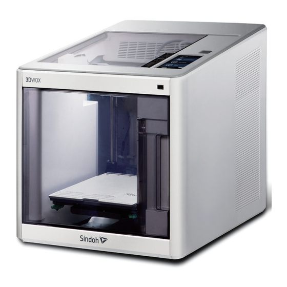
Page 30: Designation Of Parts
Preparations for Machine Operation Designation of Parts <Front> <Rear> Designation Explanation Front hatch handle Use front door hatch handle to open the front door. USB flash drive port Connect USB flash drive containing printing information and print directly from USB flash drive. LCD Control panel Screen used to control printer. - Page 31 Preparations for Machine Operation <Interior> Designation Explanation Bed height adjustment handle Handles used to control levelling of bed. Removable bed handle Handles used to assemble and dismantle bed. Flexible Bed Seating space for Printable. <Nozzle> Designation Explanation Main Body Main Body. Transparent Screen A transparent screen through which user can watch the printing.
-
Page 32: Installation (Product Connection, Cartridge Setup And Includes Software Installation)
Preparations for Machine Operation Installation (Product connection, Cartridge Setup and Software installation) Device Connection On the rear side of the machine, connect the power cable to the power socket. Next, connect the power cable to the power outlet. Press the power button, located on top of the machine. After main menu is displayed on the LCD screen, install the cartridge (Refer to UI manual “LOAD”... - Page 33 Preparations for Machine Operation Select language, press “Next” program will start installation. Saving files and installing. Install additional files required by the program.
- Page 34 Preparations for Machine Operation After installation, “3DWOX Desktop” icon should be available on your desktop.
-
Page 35: Slicer Program Manual (Usage)
Preparations for Machine Operation Slicer Program Manual (Usage) - E-mail feature must be selected on the UI menu before being used. Standard Screen Manual After installation is complete, double click on the icon created on your desktop, screen like below will appear. Explanation are the following. -
Page 36: Functions And Information
Preparations for Machine Operation Designation Explanation Print button Connect to printer, using the network print will print already sliced model. 3D model Using the import button, Import and open model data. Printer frontal Indicates direction of printable, illustrating user which direction object will be indication printed. -
Page 37: Profile Value Setting
Preparations for Machine Operation Profile Value Setting Printing, slicing requires variety of parameter values. From filament accuracy to material, Slicing angle on each level and printing speed, are parameter values needing to be set. Detail description Click located on left bar. According to selected mode a window will pop up, user can input desired profile calue. - Page 38 Preparations for Machine Operation Advanced Settings (1) Advanced Settings (2) Advanced Settings (3) - OK button: Saves all values on menu and closes window. - Apply button: Save all values on menu does not close menu window. - Cancel button: Does not save values and closes menu window.
- Page 39 Preparations for Machine Operation When the printer in use is DP102, The settings screen of DP102 is same as the above. When the printer in use is DP201, For 3DWOX DP201, the settings screen would change as below. <Easy Mode> - The material is fixed to be PLA and other materials are unavailable.
-
Page 40: Filament Condition Indicator
Preparations for Machine Operation Advanced(2) - The Printer controls the cooling settings automatically. Besides the changes above, other settings screens would be the same as DP200’s. Filament Condition Indicator Printer automatically reads condition of filament in printer and displays on screen. Detail description Current default printer name Current quantity, condition and material of filament inside the printer... -
Page 41: Model Maneuvering
Preparations for Machine Operation Detail description 3D Model View This mode renders the 3d model imported by user and displays on screen. In this mode user is able to change position, angle and size of the 3D model. Support Edit View In any case if printable model featured a slant, to counter this attribute a support has to be inserted on the lower half of the model, allowing a prefect print. -
Page 42: Adjusting Model Size
Preparations for Machine Operation Adjusting Model Size Scale and length of selected model on screen can be adjusted. Size of scale can controlled in direction of 3 axis. Size of length can controlled in direction of 3 axis Creates adjustments fit to original scale. Adjust model to maximum size available. - Page 43 Preparations for Machine Operation Detail description File Loads 3D model (equivalent to load button) Imports external G-code files and display the path. After slicing model saves created G-code. MODE 3DWOX offers users two types of different modes for slicing. “EASY MODE” offers an already set profile setting for a fast and easy print, “ADVANCED MODE” allows users to set each and every detailed value for user preference, to achieve desired print.
- Page 44 Preparations for Machine Operation - Maximum Printing Size: Insert maximum printable size of the connected printer. - E-mail : Feature that sends the printing status to the entered e-mail address. Under ‘email’, input the recipient email address(es) and select the number times that you wish to send the notification emails.
- Page 45 Preparations for Machine Operation <Start/End G-code> Check standard settings for start/end code, text can be also modified which can also be applied to sliced model. <Import/Export Profile> This function allows user to import ready made profile parameter values or export made values for slicing. File format for profile are *.ini editing is available through “notepad”.
- Page 46 Preparations for Machine Operation <Add Network Printer> Automatically searches and finds available printers in network. Select from the found printers and press “add”, then selected printer will be added to “My Printer”. <Find Printer by IP Address> Add by inserting specific printer ip address. After typing the IP address, press “add”.
-
Page 47: Printing (Basic Functions)
Preparations for Machine Operation Analysis This function analyzes the 3D model and pre-calculates and notifies user of any problems that might arise. (refer to Advanced Functions) Help User can gain access to information on Language, Keyboard Shortcuts, Online FAQ and Program Updates. Printing (basic functions) Explanation of the steps to printing 3D model using base functions. -
Page 48: Basic Parameter Setting
Preparations for Machine Operation Basic Parameter Setting Click on the [SETTING] button to change any parameter values. eg) change the slicing layer height value which does determine the quality of the printable or adjust the support application. Slicing After checking 3D model is positioned on top of the bed, selecting layer mode will apply the parameter values and execute the slicing. -
Page 49: Print
Preparations for Machine Operation Print There are 3 different procedures to print a sliced model. <Usage of Removable USB flash drive> After model has been sliced on the menu bar select “save G-code” Save the created G-code into user USB flash drive. On the front of the printer, the USB port is available. - Page 50 Preparations for Machine Operation Conversion to Support Editing View Mode Click View conversion button located left hand side of screen. Edit mode will change to Support edit view (look under setting - advanced mode - support type) either “Touching Buildplate” or “Everywhere” has to be selected for support to be created.
- Page 51 Preparations for Machine Operation <Removing Support> To remove support, hold the Ctrl key and with the mouse click on the active area of the edit cross section. The area that has been selected will turn black (inactive), Supports that have been created will be removed. Support Edit Cross Section Maneuvering Length of Support is determined by having the cross section as the center and creating a support vertically both ways until a shape is created.
- Page 52 Preparations for Machine Operation Support Edit Maneuvering Slider Current Support edit palette size Minimum size of editing palette Maximum size of editing palette To edit the support inside, the model user has to move the edit cross section. Use the support edit slider to maneuver around.
-
Page 53: 3D Model Analysis Function
Preparations for Machine Operation 3D Model Analysis Function 3DWOX has the function where before printing the program analyses the shape of the 3D model and informs user of any problems that might occur. Analyses the layers of the slicer directed cross sections, and analyses the countergra dient of the shape in the z axis direction. - Page 54 Preparations for Machine Operation Analysis Control Window Controls the thickness. Display Overhang function on/off. Controls the angle of Overhang. Thickness Analysis Function This function will indicate to user of any layers that are thinner than the set minimum thickness value. If minimum thickness layer was set to 0.4mm, any layers that are thinner than 0.4mm, (in the order of BLUE, GREEN and RED) will be indicated, and user will be notified with any problems that might arise.
-
Page 55: Function To Calculate Optimal Printing Direction
Preparations for Machine Operation Function to Calculate Optimal Printing Direction 3DWOX Desktop has a feature which caculates and recommends the user the most optimal direction for printing. On the basis of pre set standards,this feature caculates 6 different printing directions having the Bed as the base and shows the optimal direction to the user. - Page 56 Preparations for Machine Operation In Analysis menu, select “Optimal Printing Direction” and a window coherent to below will appear, Parameter Settings Calculate Graph for each evaluation criteria Calculation for each 6 different direction would be initiated once the user clicks on the Caculate button. Results of 6 different directions of the model will be displayed, and each direction will be ranked on the evaluation results.
- Page 57 Preparations for Machine Operation Select the preferred direction by pressing the “select” button, and the corresponding model will have changed into the direction selected. (Rank 2 had been selected in coherent image)
-
Page 59: Ui Menu Function Description
DP201 Series USER MANUAL UI Menu Function description... - Page 60 UI Menu Function description UI Menu Function description CARTRIDGE LOAD UNLOAD UNLOCK SETTING X,Y,Z ALL,X,Y,Z X, Y, Z EXTRUDER BED LEVELING Z OFFSET Move Save NOZZLE CLEANING CLEANING CASE NETWORK Wifi (SELECT SETTING) *ALWAYS SELECT NETWORK LIST DHCP Static Clear SSID Wired (SELECT SETTING) DHCP...
-
Page 61: Cartridge
UI Menu Function description LANGUAGE *한국어 中文 English EMAIL SETTING E-mail Address E-mail Server Info Address Port UNIT Celsius(˚C) Fahrenheit(˚F) meter(m) feet(ft) TIME SETTING YYYY, MM, DD, HR, MIN TIME ZONE SETTING SOFTWARE UPDATE INFORMATION Name Change Name & PW Name Confirm PW Cancel... -
Page 62: Load
UI Menu Function description LOAD This function automatically loads filament to the Nozzle. From the HOME screen press the [CARTRIDGE] button. Press [LOAD] to activate Cartridge load. -
Page 63: Unload
UI Menu Function description After confirming to user for cartridge load by pressing [OK], cartridge load will automatically proceed. The filament is then fed to the nozzle. Next step is the nozzle reaching its target temperature with the fixing of the filament into the heated nozzle. After the process has finished, screen will automatically return to the [HOME] screen. - Page 64 UI Menu Function description Press [UNLOAD] to activate Cartridge unloading. After confirming on user Cartridge unload action by pressing [OK] Cartridge unloading will automatically procceed. To remove the filament from the nozzle target temperature has to be reached, then after the removing procedure will being.
-
Page 65: Unlock
UI Menu Function description UNLOCK This Function is to remove the cartridge from the printer. To activate the unlock function there are two ways, after filament has been [UNLOAD] automatically moving on, or user optionally navigates to the function. In the case of coming to the [UNLOCK] screen after [UNLOAD] as finished. For 10 seconds [LOCK] states will be deactivated, user can detach cartridge from printer. - Page 66 UI Menu Function description After [UNLOAD], user will view the [UNLOCK] screen to unlock and remove the cartridge; however, if user would like to unlock cartridge for removal at a preferable time, follow the below steps. From home screen press [CARTRIDGE] button. Press [UNLOCK] to activate UNLOCK function.
- Page 67 UI Menu Function description For 10 seconds [LOCK] states will be deactivated, user can detach cartridge from printer. ※If the cartridge can’t be pulled out even after “unlock”, gently push it forward and then try to pull out again. After 10 seconds printer will automatically change to [LOCK] states, to activate [UNLOCK] a button will appear.
-
Page 68: Settings
UI Menu Function description Settings SETTING X, Y, Z ALL,X,Y,Z X, Y, Z EXTRUDER BED LEVELING Z OFFSET Move Save NOZZLE CLEANING CLEANING CASE NETWORK Wifi (SELECT SETTING) *ALWAYS SELECT NETWORK LIST DHCP Static Clear SSID Wired (SELECT SETTING) DHCP Static LAMP (SELECT SETTING) -
Page 69: X, Y
UI Menu Function description EMAIL SETTING E-mail Address E-mail Server Info Address Port UNIT Celsius(˚C) Fahrenheit(˚F) meter(m) feet(ft) TIME SETTING YYYY, MM, DD, HR, MIN TIME ZONE SETTING SOFTWARE UPDATE X, Y, Z Use to change the position of the X, Y, and Z axis of the Nozzle. From home screen press [SETTING] to approach the settings menu. - Page 70 UI Menu Function description Press the [X,Y,Z] button to enter X, Y, Z. Press [0.1], [1], [10], [100] to select the distance user wants to move. [All][X][Y][Z] press these buttons to set each axis to home location.
-
Page 71: Extruder
UI Menu Function description EXTRUDER Function is to fine control the filament to its right position. From home screen press [SETTING] to approach the settings menu. Press the [EXTRUDER] button to enter EXTRUDER settings. - Page 72 UI Menu Function description To Control [EXTRUDER] temperature must be high, Nozzle temperature will be raised. Press (1, 10, 50, 100) to select amount of distance user desires. Like the picture below press on the direction user wants to move the filament.
-
Page 73: Bed Leveling
UI Menu Function description BED LEVELING Function used to set the level of the bed. From home screen press [SETTING] to approach the settings menu. Press the [BED LEVELING] button to enter BED LEVELING settings. - Page 74 UI Menu Function description On the SETTING page, user is able to perform bed leveling. There are 3 steps. From the center level to the top level will be measured then both sides of the bottom level will be measured. If the height of the bed is perfect then levelling process will be finished but if the bed and nozzle is not in the correct fix, screws will appear informing user the direction and the number of click(angle) of the fix.
-
Page 75: Z Offset
UI Menu Function description When all works are done return to before page. Z OFFSET ※ After bed leveling, it is highly recommended to check the z-offset. This Menu allows user to control the GAP in between Nozzle and BED. Standard is 0.25mm, User adjustment can be made to fit condition. - Page 76 UI Menu Function description Press the [Z OFFSET] button to access Z Offset screen. Default value is 0.25mm, Use [+], [-] buttons to move 0.05mm...
-
Page 77: Nozzle Cleaning
UI Menu Function description Use the [MOVE] and [SAVE] button to see the nozzle move, and save user settings . Saved changes of GAP settings values will be applied in the beginning of a print. These values will be reset if bed leveling is initiated. NOZZLE CLEANING Function used when nozzle needs cleaning of left over filament debris. - Page 78 UI Menu Function description Press the [NOZZLE CLEANING] button to access NOZZLE CLEANING. In order to get rid of all left over filament debris, nozzle will raise its temperature. when reached it target temperature printer will go on to the next step and remove the filament debris. Once finished message will appear press [OK], printer will return to the settings screen.
-
Page 79: Cleaning Case
UI Menu Function description CLEANING CASE Function used to clean out the case for the collected filament debris. From home screen press [SETTING] to approach the settings menu. Press the [CLEANING CASE] button to enter CLEANING CASE settings. -
Page 80: Network
UI Menu Function description Entering Cleaning Case, the nozzle will automatically position itself to the left side to give vision and reach of the case. Like shown in the image, empty the CASE, press [OK] when done and user will be returned to the settings screen. - Page 81 UI Menu Function description Press the [NETWORK] button to access network configuration screen. Network Settings default screen will show Wired (connection using LAN line). Press [DHCP] for automatic loading of the user IP address; however, if user would like to manually input a fixed IP address press [Static] and fill in the information required.
- Page 82 UI Menu Function description In any case to use Wifi press the [Wifi] button on top. User can select the usage of Wifi [ON/OFF]. In cases of using Wifi click on [Choose a network…] text, printer will load all available Wifi connections.
- Page 83 UI Menu Function description Select user Wifi from the list and attempt to connect printer through Wifi. For Wifi with password locks, type in the correct password in the dialog box and enable the connection. After successful connection printer may ask for [DHCP], [Static] similar to WIRED. When all settings are finalized press [OK] to save settings.
-
Page 84: Lamp
UI Menu Function description LAMP Menu to configure settings for machine lamp. From home screen press [SETTING] to approach the settings menu. Press [Next] button to move to the next page and enter [LAMP] . - Page 85 UI Menu Function description Settings available for [LAMP] are [ALWAYS TURN ON LAMP, UI control & PRINTING TURN ON LAMP, TURN ON ONLY DURING PRINTING, TURN ON DURING UI CONTROL, ALWAYS TURN OFF LAMP]. Using the ar rows select the favored setting and press [OK] button.
-
Page 86: Bed Lowering
UI Menu Function description BED LOWERING Use this function, in times of moving printer to a different location. Bed will be lowered to the bottom and will be fixated into position. Enter the menu by tapping on the [SETTING] button from the home screen. Tap on the [Next] button to move to next page, where the [BED LOWERING] button is located. -
Page 87: Test Print
UI Menu Function description After confirming activation of bed lowering, press the [OK] button, printer will initiate bed lowering. TEST PRINT This function allows the user to test print a sample model already programmed in the printer. From home screen press [SETTING] to approach the settings menu. - Page 88 UI Menu Function description Press [Next] button to move to the next page and enter [TEST PRINT] . Select the test file wanting to print.
-
Page 89: Power Saving Mode
UI Menu Function description POWER SAVING MODE Function to set timer for printer energy saver mode. From home screen press [SETTING] to approach the settings menu. Press [Next] button to move to the next page and enter [POWER SAVING MODE] . -
Page 90: Beep Sound
UI Menu Function description Currently available energy save mode options are [0 ~ 100 min] . Time variation is in 5mins, select the desired time using the [ +, - ] then press [OK] button to save changes. BEEP SOUND In this menu, user is able to select settings for the Beep sound, user can set sounds louder or turn it off completely. - Page 91 UI Menu Function description Tap on the [Next] button to move to next page, where the [BEEP SOUND] button is located. Currently available sound settings are [Off, Cancel, Soft, Loud] . Select the desired setting and press the [OK] button to save settings.
-
Page 92: Nozzle Setting
UI Menu Function description NOZZLE SETTING Use this menu only when you have exchanged the nozzle.(Refer to P.5-9 4.3 Exchanging Nozzle ) Enter the menu by tapping on the [SETTING] button from the home screen. Tap on the [Next] button to move to next page, where the [NOZZLE SETTING] button is located. - Page 93 UI Menu Function description “NOZZLE SETTING” menu is a function that should be used after replacement to a new nozzle. Entering the menu, a notification message will pop up press [OK] button to move on to the next menu. Press the white section of the numbers to insert the values for the new nozzle. Each nozzle has its specific value, this value will influence the GAP between nozzle and bed after bed leveling.
-
Page 94: Language
UI Menu Function description LANGUAGE Menu to set language for machine. From home screen press [SETTING] to approach the settings menu. Press [Next] button to move to the next page and enter [LANGUAGE] . - Page 95 UI Menu Function description Currently supported languages are [Korean, Chinese, English] . Using the arrows select the favored language and press [OK].
-
Page 96: E-Mail
UI Menu Function description E-MAIL The printer takes an image of the current printing status and sends the information to the set email. Printer will send information of completion (%) based on the PC program standard settings. Maximum of 10 emails can be sent. - Page 97 UI Menu Function description Configure the setting for email notification to be sent out on 3DWOX. Only the information that is required for sending the email is set up on the printer and the recipient information has be set up on the slicer program. Catergory Details Email Address...
- Page 98 UI Menu Function description To check the detailed setting values, please refer to the setup information from your email service provider. For the set up to use the outgoing email service, please find information from internet search or your email service provider’s instructions.
- Page 99 UI Menu Function description Under "Sign-In&Secruity" click "Device activity & notifications" Scroll down and there is a "Allow less scure apps" criteria. Set it to "On" and you will be enble for use. Printer Setting Set "smtp.google.com" for the settings of the email address. For Google, 25587 ports are compatible.
-
Page 100: Unit
UI Menu Function description UNIT Settings for the units of measurments displayed on the printer. From the home screen, enter the settings menus by pressing the [SETTING] button. Press the [Next] and enter the [UNIT] menu. -
Page 101: Time Setting
UI Menu Function description User is able to change the measuring units for temperature and length. TIME SETTING Displays the current time, and user is able to change time to user preference. From the home screen, enter the settings menus by pressing the [SETTING] button. - Page 102 UI Menu Function description Press the [Next] and enter the [TIME SETTING] menu. If YYYY, MM, DD, HH, MM is not correct, user is able to set it to the correct date/time.
-
Page 103: Time Zone
UI Menu Function description TIME ZONE Displays the current time and time zone, user is able to change and set to user preference. From the home screen, enter the settings menus by pressing the [SETTING] button. Press the [Next] and enter the [TIME ZONE] menu. -
Page 104: Web
UI Menu Function description Displays the current time and time zone, user is able to select and set to user preference. Once Time Zone has been set, the printer will restart to apply the new settings. 3dprinter homepage for the user to view. From the home screen, enter the settings menus by pressing the [SETTING] button. - Page 105 UI Menu Function description Press the [Next] and enter the [WEB] menu. The 3dprinter homepage will be opened and user can view the information of user preference. The company website address is http://3dprinter.sindoh.com/...
- Page 106 UI Menu Function description S/W UPDATE With the printer connected to the internet user is able to download the latest software. From the home screen, enter the settings menus by pressing the [SETTING] button. Press the [Next] and enter the [S/W UPDATE] menu.
- Page 107 UI Menu Function description Press the [Start Update] button, and printer will start updating. After it has finished, restart the printer and updates will be applied.
-
Page 108: Information
UI Menu Function description Information INFORMATION Name Change PW & Name Name Confirm PW Cancel Model Name Serial No. Version Company Website HISTORY Guide In this menu user is able to view the detail information of the printer, and is able to set name and PW. Moreover in the [HISTORY] menu user is able to view all the records of past works. - Page 109 UI Menu Function description To set password and name for printer enter [NAME AND PIN change…]. Type in user password to enter menu, type in new name and password after finishing press [OK] to save changes. - *Initial password is ‘0000’.
- Page 110 UI Menu Function description Under [Information] , press the [Guide] button on the screen and user will have access to the "quick guide" for the printer. In the outside [INFORMATION] screen all the information of the printer can be viewed.
-
Page 111: Printing
DP201 Series USER MANUAL Printing... -
Page 112: Printing With Usb Flash Drive
Printing Printing User can print printables via USB flash drive, PC Lan or Wireless networking. After booting the printer, if printer screen displays like below then it is ready to print. Printing with USB Flash Drive Connecting USB flash drive to machine. In order to print using an USB flash drive, insert the flash drive into the USB port. - Page 113 Printing Printing Files Select the file user wants to print in the USB list. Preview Printing Model Once selected, a preview of the model this is planed to the be printed will appear.
- Page 114 Printing Printing Once [ ] is pressed nozzle will raise temperature, once target temperature is reached printer will begin printing. Pausing Print Pressing [ ] during a print will pause the entire operation. Press [ ] again and nozzle temperature will raise again, reaching its target temperature printer will continue printing.
- Page 115 Printing Terminating Printing During print pressing [ ] button a message will emerge confirming user’s action to cancel printing, once confirm ing action it will immediately cancel all printing. Another message requesting the removable of left print will popup press [OK] and screen will return to home screen.
-
Page 116: Printing Via Pc
Printing Printing Via PC Prepare PC connected to concurrent network of the printer. Run PC printing program. Press the “Print” button. Following Steps (Same as steps 3~7 of printing via USB) - For fan speed configuration, Pause, operation termination, please refer to "USB printing" section. Next print job You can check the print jobs on queue and delete them. - Page 117 Printing The print jobs on queue are listed. You may click the list to look at the information of the print job and delete it if necessary.
-
Page 119: Printable Verification
DP201 Series USER MANUAL Printable Verification... -
Page 120: Detaching Printable
Printable Verification Printable Verification Detaching Printable Lowering the Bed After printing is finished, wait until the bed is lowered to the bottom of the printer. Detaching Bed The Flexible Bed is detached if you hold the bed handle and lift it. You can easily detach a large output if you insert a plastic hera in a direction of lower left corner of the bed as shown in the picture. - Page 121 Printable Verification Detaching Printed Detach the object from the Flexible Bed. The object can be easily detached by bending the Flexible Bed up and down. - Please do not use any tools with sharp edges as those can damage the surface of the bed. Bed Installation After a period of time bed locking will automatically deactivate itself, if bed is unlocked, before installation press the lock button again to fix the bed into position.
-
Page 122: Improving Printing Quality
Printable Verification Improving Printing Quality Nozzle, Bed temperature Environmental factors (temperature, humidity) can affect the quality of the printed product. There is no absolute value for optimum temperature, Testing various temperatures and finding the optimum temperature is the only process. Material Nozzle Optimum Temperature 190℃... - Page 123 Printable Verification When printing a model with thin leaves on its surface When printing a model with a thin rib shaped part as shown in the picture below, go to [Advanced Mode] → [Advanced Mode (3)] and then activate [Print Only Follow Mesh Surface] option to improve the printing quality.
-
Page 124: Case Of Power Outage
Printable Verification Case of Power Outage Open the Front door like the image below turn the belt counter-clockwise motion. Bed will decline, remove printing product and turn the power on. -
Page 125: If Problems Persist
Printable Verification If problems persist. Please visit http://3dprinter.sindoh.com... -
Page 127: Chapter 5 Maintenance
DP201 Series USER MANUAL Maintenance... -
Page 128: Machine Cleaning
Maintenance Machine Cleaning Cleaning Case Maintenance On the LCD, if a message requesting for the cleaning of the cleaning case pops up, detach the cleaning case and clean all the filament debris inside the case. - If in need for further cleaning, on the menu, under settings, select cleaning case. Printer will set to cleaning position. -
Page 129: Error Message And Solutions
Maintenance Error Message and Solutions Message Message definition Solution Booting Waiting for Message means on the first boot Once booting as finished and is able to Booting this machine. user must wait until booting as function message will disappear. finished. EC301~308 (Nozzle) Message appears due to Reboot the printer, if problem presist then... - Page 130 Maintenance Message Message definition Solution EC 432 Occurs when printer is able [OK] button will appear press the button to Unable to read SMART CHIP. to sense filament inside but is merge to UNLOAD screen. Reinstall car- Unload cartridge and reinstall unable to detect cartridge.
- Page 131 Maintenance Message Message definition Solution EC 1001 Press the [OK] button, and the pop up This error code will appear if the Model has exceeded the printing model has exceeded the message will disappear. minimum print range of the minimum print range. "X"...
-
Page 132: Problems And Solutions
Maintenance Problems and Solutions 3.1 If filament is not excreted from the nozzle (Fix for EC 401) Follow the UI instructions and start the auto recovery process, after the recovery process if problem persists follow the below steps. Initiate cartridge unlock. → Remove the cartridge from the printer.→ Use the extruder jog mode to remove the filament. -
Page 133: In Cases Where Filament Between Extruder And Nozzle Is Disconnected
Maintenance In Cases where Filament between Extruder and Nozzle is Disconnected Remove the Snap-Ring on the fitting in the nozzle and pull out the tube. Use Extruder mode and move the filament towards the nozzle to push out the disconnected filament. When you see the other end of the disconnected filament, pull out with your hand gently. -
Page 134: Methods Of Exchanging Consumables
Maintenance Methods of Exchanging consumables Exchanging Bed Flexible Bed is consumable. Although the Flexible Bed’s surface has been processed for attachment of an output without using glue or tape, it can lose adhesive strength due to user’s habits or shape of the output or numerous number of printings. In such cases, please replace the Flexible Bed with a new one. -
Page 135: Exchanging Nozzle
Maintenance Exchanging Nozzle Methods of Detaching Nozzle Initiate [Cartridge] - [Unload] in the UI Initiate detaching process ONLY after power of machine is turned OFF, and after all power cables are disconnected. Remove Snap-Ring. SNAP-RING Press the tube holder and pull the tube to remove. TUBE TUBE HOLDER... - Page 136 Maintenance Push the hook on the top, and lift open the cover. HOOK COVER Push the 2 hooks on the harness connector to disengage the connector. To remove the left hand side connector, press on the hook and once you hear a click sound. Then you can safely disconnect.
-
Page 137: Assembling The Nozzle
Maintenance Assembling the Nozzle Initiate process ONLY after power of machine is turned OFF, and after all power cables are disconnected. With the cover lifted up attach the nozzle. The Nozzle will attach with power of the magnets, granting this please check the condition of the attachment. NOZZLE Insert the 2 connectors. - Page 138 Maintenance - Please be careful not to position the harness near the left, right and center section of the cover. The harness can get caught in between covers when closing. Caution Harness Insert Tube. - Approx. 30mm of the tube is inserted. Push the tube in until the black indicator is unable to be seen. TUBE...
- Page 139 Maintenance Slightly lifting the tube insert the Snap-Ring. Insert the Snap-Ring in between the Fitting and Holder. SNAP-RING SNAP-RING INSERTION Finally, push tube til the end and verify the insertion - Approximately 1.5mm can be additionally inserted. TUBE Use the “CARTRIDGE-LOAD” command to finish the cartridge loading process.
-
Page 141: Chapter 6 Appendix
DP201 Series USER MANUAL Appendix... -
Page 142: Consumables Category (Material, Color)
Appendix Consumables Category (Material, Color) Material: PLA Color: white, black, gray, green, blue, yellow, red... - Page 143 Notice to Users Type Notice Please acknowledge that equipment is Class A equipment Class A EMC (commercial telecast (electromagnetic compatible) equipment) equipment, and should not be used in household locations Equipment is Class B EMC Class B equipment (electromagnetic compatible) (domestic telecast equipment, for household purposes, equipment)
Need help?
Do you have a question about the DP201 Series and is the answer not in the manual?
Questions and answers