
Related Manuals for Wiener VM-USB

Summary of Contents for Wiener VM-USB
- Page 1 VM-USB User Manual WIENER, Plein & Baus GmbH www.wiener-d.com Rev. 3.4.1, December 28, 2007...
- Page 2 No part of this product, including the product and the software may be reproduced, transmitted, transcribed, stored in a retrieval system, or translated into any language in any form by any means with the express written permission of W-I VM-USB and CC-USB are designed by JTEC Instruments. WIENER, Plein & Baus GmbH www.wiener-d.com...
-
Page 3: Table Of Contents
Installation for Windows Operating Systems ............ 9 Installation for Linux Operating Systems............12 Firmware upgrades .................... 12 General Architecture of VM-USB and its User Interface .........14 Action Register (Address = 1 / 0x1)..............14 VME Command Generator / EASY-VME (Address = 4 / 0x4) ....15 VME Command Stacks.................. - Page 4 Guide to List Mode Data Acquisition with VM-USB..........35 LIBXXUSB Library for Windows and Linux ............36 xxusb_devices_find ..................... 36 xxusb_device_open ..................... 36 xxusb_serial_open....................37 xxusb_device_close ..................... 37 xxusb_reset_toggle....................38 xxusb_register_write ..................38 xxusb_register_read ................... 39 xxusb_stack_write ....................39 xxusb_stack_read ....................40 6.10...
-
Page 5: General Description
PC or USB activity, other than reading out suitably formatted data buffers. The VM-USB can be also programmed to act as a VME slave with respect to a master crate controller, while performing master operations on other data acquisition modules. For example, it can be programmed via the VME bus to perform the readout of multiple VME modules, with data buffering in a 24-kByte FIFO. -
Page 6: Data Transfer Modes
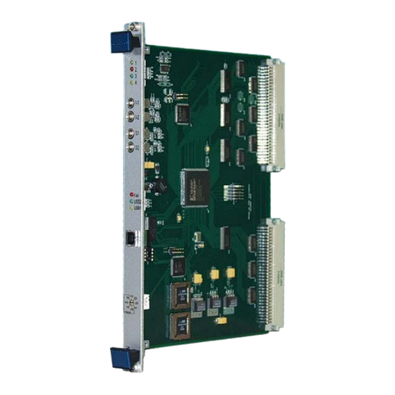
Long USB2 bulk transfers of up to 4 MByte, both write and read. • Highly customizable. • 1.3 VM-USB Front panel 4 user LED’s 2 user inputs Lemo / NIM 2 user outputs Lemo / NIM Failure LED / USB 1 or 2 indicator USB port Firmware selector (1 –... -
Page 7: Technical Data
1.6 Slave Module Base Address Jumper Settings The VM-USB module can be used as a VME slave in A32, A24 or A16 mode. For this purpose the base address BADR can be selected via 5 jumpers, which define bits 27- 31(A32), 20-24(A24) or 12-16 (A16) (always 5 most significant bits of the VME address). -
Page 8: Block Diagram
- Three-Stage Pipelined FIFO array(22 kBytes) Master - Control Unit USB Controller - FX2 CY7C68013 IC OUT FIFO - USB Out FIFO (Relative to Host) IN FIFO - USB In FIFO (Relative to Host) WIENER, Plein & Baus GmbH www.wiener-d.com... -
Page 9: Vm-Usb And Usb Driver Installation
2.1 Installation for Windows Operating Systems 1. Switch off the VME crate and remove the power cord. Plug in the VM-USB on the first left slot 1 if needed as system controller and secure it with the front panel screw. Switch on the VME crate. - Page 10 Press Enter to select this driver and to close the window. 7. The WIENER VM-USB driver should be listed and highlighted in the driver list. The driver is not digitally signed which however does not have any effect on it’s functionality. Press Next to finish the installation.
- Page 11 8. The “New Hardware Wizard” should copy all driver files into the Windows System32 folders and report a successful installation. WIENER, Plein & Baus GmbH www.wiener-d.com...
-
Page 12: Installation For Linux Operating Systems
Linux specific details are located in the readme file on the software CD that you received with your module. 2.3 Firmware upgrades The VM-USB is shipped with the latest firmware for the FPGA loaded however, new versions of it may be available on the web. Please occasionally check at www.wiener-d.com ->... - Page 13 Select “Yes” or go to the Flash ROM Operations page and click program. Open the file of the latest firmware (xxx.bit) When done one has to reset the controller or switch the selector switch to the corresponding run location (C1-C4) and power cycle the crate. WIENER, Plein & Baus GmbH www.wiener-d.com...
-
Page 14: General Architecture Of Vm-Usb And Its User Interface
NIM input I1, detection of a valid VME IRQ, or a USB trigger of scaler readout. When bit 0 of the Action Register is set, VM-USB is in data acquisition mode; otherwise it is in interactive mode. -
Page 15: Vme Command Generator / Easy-Vme (Address = 4 / 0X4)
VM-USB issues VME commands, reads the data received in response to them, and buffers the data in a data buffer. When the buffer (up to 26kB) is full, VM-USB dumps it to the FIFO of the USB controller IC for the retrieval by the host. It is this data buffering that allows one to take advantage of the superior band width of the USB2 interface in bulk transfer mode and to achieve throughputs in excess of 30 Mbytes/s. -
Page 16: Internal Register File
Offset = 4 / 0x4 The global mode register has the following 16-bit structure: Bits 15 14 13 12 11 - 9 3 - 0 Value BusReq HeaderOpt EvtSepOpt B u f f O p t WIENER, Plein & Baus GmbH www.wiener-d.com... - Page 17 The BusReq bits identify the VME Bus Request level (0 to 4) to be used by VM-USB, when not operated as a slot 1 controller (bus arbiter). BusReq=1,2,3, and 4 cause BR0, BR1, BR2, and BR3 lines to be used, respectively.
-
Page 18: Data Acquisition Settings Register - Read/Write
VME DTACK VME BERR VME BERR VME BERR VME BERR VME Bus Request VME Bus Request VME Bus Request VME Bus Request VME Bus Granted VME Bus Granted VME Bus Granted VME Bus Granted WIENER, Plein & Baus GmbH www.wiener-d.com... -
Page 19: User Devices Source Selector - Read/Write
3.4.5 User Devices Source Selector - Read/Write Offset = 16 0x10 There are six user devices set up within the FPGA resources of the VM-USB – two NIM outputs, O1 and O2, two delay and gate generators or pulsers, DGG_1/P_1 and DGG_B/P_1, and two 32-bit scalers, SCLR_A and SCLR_B. -
Page 20: Delay And Gate Generator / Pulser Registers - Read/Write
Pulser repetition period = Gate + Delay DGG_A 16-31 DGG_A 0-15 Gate Delay_fine DGG_B Offset = 24 / 0x18 DGG_B 16-31 DGG_ B 0-15 Gate Delay_fine DGG_ Ext Offset =56/0x38 DGG_B Ext (16-31) DGG_A Ext 0-15 Delay coarse Delay coarse WIENER, Plein & Baus GmbH www.wiener-d.com... -
Page 21: Scaler Registers Slr_A And Sclr_B - Read
Stack ID can be shared by many interrupts. Upon detection of a valid interrupt, VM-USB executes the stack linked to this particular interrupt. The Interrupt Service Vectors are stored in four registers at VM-USB register addresses 0x28 to 0x34 in arbitrary order and contain two vectors per register. -
Page 22: Usb Bulk Transfer Setup Register - Read/Write
Therefore, one must strive to reduce the number of transfers by extending the length of bulk transfers. VM-USB, by default closes USB buffer (generates a “packet end”) either at the end of the data buffer or at the end of event. This guarantees bulk transfer lengths of only 26 kBytes for short events and lengths equal to event lengths, in the case of long events. - Page 23 Because of the architecture of the VM-USB, writing of the IRQ mask and reading it back is not as easy as writing to other registers. This is because the mask resides in the Interface CPLD (top XC95144XL CPLD, named U7) and there are no dedicated connections for this purpose.
-
Page 24: Communicating With Vm-Usb
USB2 port of the VM-USB using bulk-transfer mode. Borrowing from the USB language, the buffers to be written to the VM-USB will be called Out Packets, and they are sent to pipe 0 of the USB port. The buffers to be read will be called In Packets, and they are read from pipe 2 of the USB port. -
Page 25: Writing Data To The Register Block
VME Command Generator (VCG) have identical structure, differing only in the Target Address and in the allowed length. Writing a stack to the VM-USB the first line of the USB out packet contains the Target Address (see table below). The following stack data define first the length (number of following lines) as well as the starting address (0 –... -
Page 26: Structure Of The Vme Stack
The VME Command Generator (VCG) is an internal module that interprets the information found either in the VME Stacks (when VM-USB is in data acquisition mode) or in the Out Packet received from the USB port (when VM-USB is in interactive mode / EASY-VME mode). - Page 27 MRK MRK=1 indicates writing of a marker word directly into the output data stream. DLY DLY=1 indcicates that the VM-USB should pause for a specified amount of time before executing the rest of the out packet. The delay time is specfied in microseconds in the BLT bits (24-31).
-
Page 28: Single Transfer Commands
Since the stack can be quite complex, it is advisable to write a proper routine or macro to set it up. As a convenient option, one may utilize the XXUSBWin Windows application to build the stack and save it to disk. 4.5.11 Single Transfer Commands WIENER, Plein & Baus GmbH www.wiener-d.com... -
Page 29: Block Transfer Commands
Mode Word identifies in its bit 13 (value 0x2000) the command as a Write Marker command. This Mode Word may be simply 0x2000 (the AM code is disregarded) and must be followed by a 32-bit marker data data specifying the desired marker WIENER, Plein & Baus GmbH www.wiener-d.com... -
Page 30: Use Of Hit Registers For Conditional Execution Of Stack Commands
No address word is to be inserted. 4.5.15 Use of Hit Registers for Conditional Execution of Stack Commands VM-USB allows one to use hit registers (coincidence registers) to perform conditional execution of any stack commands. To perform such a conditional execution, one must first define a module to be read as a hit register module and then identify any of the subsequent commands as conditional ones, while specifying the conditions. -
Page 31: Using Xxusbwin Application To Handle Stacks
0x78000120, both with AM=0x09. Please note that the VME command stack is based on 32-bit words but arrange in 16-bit lines, i.e. 2 consequent lines belong to one 32-bit word. Explanations are added in blue color: VM-USB Command Stack Generated on 8/29/2005 at 5:56:57 PM WIENER, Plein & Baus GmbH www.wiener-d.com... -
Page 32: Structure Of The In Packets
(up to 26 kBytes) compatible with the VM-USB functionality. All data supplied by the VM-USB is to be read from the Endpoint 6. While reading, it is important to specify the length of the buffer not shorter than the length of the actual data buffer written by the VM-USB into this endpoint. - Page 33 VM-USB has dedicated 2kWords-long event FIFO to compile events. To handle longer events, VM-USB splits the long event into parts, each of which appears as a separate event in the output buffer. The partial events are tagged by setting bit 12 of the Event Length word, except for the last part.
- Page 34 VME 32-bit Read: returns 2 words, with data bits 0-15 and 16-31, respectively: Bits D15 D14 D13 D12 D11 D10 D9 D31 D30 D29 D28 D27 D26 D25 D24 D23 D22 D21 D20 D19 D18 D17 D16 WIENER, Plein & Baus GmbH www.wiener-d.com...
-
Page 35: Guide To List Mode Data Acquisition With Vm-Usb
4. Set the trigger delay (time from the receipt of an event to the commencement of the stack execution). 5. If VM-USB is not the slot 1 controller, set up the bus request level, by writing the bus request level code into bits 12-14 of the Global Register. -
Page 36: Libxxusb Library For Windows And Linux
LIBXXUSB LIBRARY FOR WINDOWS AND LINUX A dedicated library of functions was developed to facilitate the utilization of VM-USB and its CAMAC counterpart, CC-USB. This library is called libxxusb and requires the libusb0.sys driver to be installed. It is in fact a wrapper library for the general-use libusb- win32 library available via www.sourceforge.net... -
Page 37: Xxusb_Serial_Open
While all xxusb functions rely on the libusb (www.sourceforge.net) functions while communicating with XX-USB, xxusb_device_open and xxusb_handle_close are simply macros creating aliases to usb_open and usb_close functions of the libusb library. 6.3 xxusb_serial_open Opens a xxusb device (CC-USB or VM-USB) whose serial number is given * xxusb_serial_open{ USB_DEV_HANDLE char *SerialString... -
Page 38: Xxusb_Reset_Toggle
WORD xxusb_register_write{ HANDLE hDevice, WORD wRegisterAddress, DWORD dwRegisterData Parameters hDevice [in] Handle to the XX-USB device. wRegisterAddress [in] Address of the XX-USB register. For a list of XX-USB addresses, see Remarks dwRegisterData WIENER, Plein & Baus GmbH www.wiener-d.com... -
Page 39: Xxusb_Register_Read
The xxusb_stack_write function sends a buffer to XX-USB, causing the latter to store this content in a dedicated block RAM, for use when data acquisition mode is active. This content can be read back using xxusb_stack_read function. WORD xxusb_stack_write{ HANDLE hDevice, WORD wStackType, LPDWORD lpStackData WIENER, Plein & Baus GmbH www.wiener-d.com... -
Page 40: Xxusb_Stack_Read
The physical length of the periodic (scaler) stack is 256 16-bit words for CC-USB and 256 32-bit words for VM-USB. While the stack is expected to contain properly encoded sequence of VME (VM-USB) or VME (VM-USB) commands to be performed by XX-USB, it can store any sequence of numbers. -
Page 41: Xxusb_Stack_Execute
On success, the function returns the number of bytes read from XX-USB. The valid value is twice the number of 16-bit data words returned plus 2 (CC-USB) or 4(VM-USB). The latter “overhead” bytes contain event terminator word (0xFF for VM-USB, and 0xFFFF for VM- USB). -
Page 42: Xxusb_ Longstack_Execute
DataBuffer(2) = (unsigned short)StackLength bits 16-20 DataBuffer(3 - StackLength +2) (unsigned short) stack data StackLength represents the number of words following DataBuffer(1) word, thus the total number of words is StackLength+2 Structure upon return: WIENER, Plein & Baus GmbH www.wiener-d.com... -
Page 43: Xxusb_Usbfifo_Read
6.13 xxusb_bulk_read The xxusb_bulk_read function reads the content of the USB port FIFO of XX-USB or times out whenever this FIFO has not set the “FIFO Full” flag. WORD xxusb_bulk_read{ WIENER, Plein & Baus GmbH www.wiener-d.com... -
Page 44: Xxusb_Bulk_Write
6.14 xxusb_bulk_write The xxusb_bulk_write function writes a character array to the USB port FIFO of XX-USB. WORD xxusb_bulk_write{ HANDLE hDevice, xxxx *pData, WORD wDataLen, WORD wTimeout Parameters hDevice [in] Handle to the XX-USB device. WIENER, Plein & Baus GmbH www.wiener-d.com... -
Page 45: Xxusb_Flashblock_Program
30ms between consecutive calls and incrementing the pointer to the data array by 256 on each consecutive call. The device must be in programming mode with the rotary selector in one of the 4 “P” positions and with the red “Fail” LED on. WIENER, Plein & Baus GmbH www.wiener-d.com... -
Page 46: Vm_Usb Specific Functions
The configuration file of a XC3S200 FPGA of VM-USB will occupy 512 sectors of flash memory (512 calls to the xxusb_flashblock_program). The XC3S400 FPGA of VM-USB will occupy 830 sectors of flash memory. VM_USB SPECIFIC FUNCTIONS The following functions are specific to the VM_USB. They are built on top of the general purpose functions described in section 6 and provide users with an easier and more transparent way of communicating with the controller. -
Page 47: Vme_Dgg
Data [out] Data read from the specified register Return Values On success, the function returns the number of bytes read from the VM-USB Function returns a negative number on a failure 7.3 VME_DGG The VME_DGG function allows the user to setup the characteristics of the Delay and Generator channels of the VM_USB. -
Page 48: Vme_Led_Settings
[in] Determines whether or not the LED is inverted. Valid values are: 0 – Not inverted 1 – Is inverted latch [in] Determines whether or not the LED is latched. Valid values are: WIENER, Plein & Baus GmbH www.wiener-d.com... -
Page 49: Vme_Output_Settings
1 – Is latched Return Values On success, the function returns the number of bytes from from the VM_USB. Function returns a negative number on a failure 7.6 VME_scaler _settings Configures the internal VM-USB scaler (SelSource register) WIENER, Plein & Baus GmbH www.wiener-d.com... -
Page 50: Vme_Write_32
LONG VME_Address, LONG Data Parameters hDevice [in] Handle to the XX-USB device. Address_Modifier [in] VME Address modifier VME_Address [in] VME address to write Data to Data [in] data written to the VM_USB Return Values WIENER, Plein & Baus GmbH www.wiener-d.com... -
Page 51: Vme_Read_32
On success, the function returns the number of bytes written to VM-USB Function returns a negative number on a failure. 7.8 VME_read_32 The VME_read_32 function reads a 32 bit word from a VME address. short VME_read_32{ HANDLE hDevice, USHORT Address_Modifier,... -
Page 52: Vme_Read_16
Data [in] data written to the VM_USB Return Values On success, the function returns the number of bytes written to VM-USB Function returns a negative number on a failure 7.10 VME_read_16 The VME_read_16 function reads a 16 bit word from a VME address. - Page 53 [out] pointer to an array where Data can be stored read from the VM_USB Return Values On success, the function returns the number of bytes read from VM-USB Function returns a negative number on a failure WIENER, Plein & Baus GmbH...
- Page 54 The design of the VM-USB allows one to reprogram any of the four segments of the flash memory via the USB interface. The programming and reprogramming is possible only in the...
- Page 55 Next i ‘Releasing or setting the FPGA reset: ll=xxusb_reset_toggle(EZHandle) In the above two samples, EZHandle represents the USB handle of the VM-USB and bytes() is an array storing the desired FPGA configuration file (220 kB). WIENER, Plein & Baus GmbH...
-
Page 56: Appendix B: Use Of Multiplexed User Devices
VME-like commands. The latter commands address the VME address space allocated to the VM-USB and do not generate any activity on the VME bus. Both scalers are asynchronous with respect to the VM-USB clock, each using a dedicated fast clock network driven by the selected clock signal. -
Page 57: Appendix D: Enhancments Implemented In Firmware 16000503
(in addition to bit 0). As in earlier versions, the stack ID is sent to VM-USB in the first word (2 bytes) of the USB out packet, with bit 0 of the ID mapped to bit 0 of the address word and bits 1 and 2 to bits 4 (value 16) and 5 (value 32) of the address word, respectively. - Page 58 With this option selected, the DGG will produce a train of pulses of width equal to the set gate width and the period equal to the sum of set delay and gate widths. WIENER, Plein & Baus GmbH www.wiener-d.com...
Need help?
Do you have a question about the VM-USB and is the answer not in the manual?
Questions and answers