Table of Contents
Advertisement
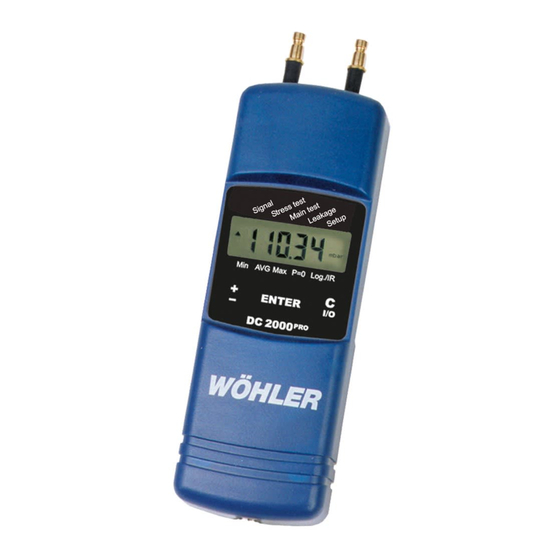
Pressure Computer Wöhler DC 2000
Contents
1.
Specifications ...........................................2
2.
Controls and connections ........................5
3.
Signal menu .............................................8
4.
Stress test (DVGW-TRGI) .......................12
5.
Main test menu (DVGW-TRGI) ...............14
6.
Leakage rates & utility life
measurements ........................................20
7.
Min, Max, AVG menu .............................21
8.
9.
Logger / data transfer ............................27
10. Changing the batteries ...........................29
11. Accessories .............................................30
12. Information on disposal ...........................30
13. Declaration of conformity .......................31
14. Warranty and service..............................33
Quick reference ........... loose leaf at the centre
The Measure of Technology
PRO
Advertisement
Table of Contents

Related Manuals for Wohler DC 2000PRO


Summary of Contents for Wohler DC 2000PRO
-
Page 1: Table Of Contents
Pressure Computer Wöhler DC 2000 Contents Specifications ...........2 Controls and connections ......5 Signal menu ..........8 Stress test (DVGW-TRGI) .......12 Main test menu (DVGW-TRGI) ....14 Leakage rates & utility life measurements ........20 Min, Max, AVG menu ......21 Setup menu for basic settings and logo 22 Logger / data transfer ......27 10. -
Page 2: Specifications
1. Specifications DC 2000 Specifications Important information Before using this instrument, carefully read and observe all notes contained in these operating instructions. Fundamentally, skilled personnel only should use the Wöhler DC 2000 the purpose that it is intended and within the specified data range. No liability is accepted under any circumstances or guarantee given for results deter- mined in conjunction with this instrument nor for any damage that may arise when using this instrument. - Page 3 1. Specifications DC 2000 1. 2 Application The Pressure Computer DC 2000 is a high-precision multifunctional meter for registering differential pressures, flow rates, temperatures, and humidities (optional). From the basic version on, this device exhibits an extremely wide dynamic range that not only takes highly sensitive measurements of mini- mum draughts and gas pressures in the pascal range, but also lets the user measure leakage rates and examine sealing properties for main assessments as per DVGW-TRGI and conduct measurements for load tests during pre-...
- Page 4 1. Specifications DC 2000 Measured values Differential pressure measurements (temperature-compensated piezo bridge) Measuring range: ±2 bar 1 Pa resolution in measuring range -125.00 hPa to +125.00 hPa, otherwise 10 Precision: < 3% of measured value, better than ±6 Pa within a range of ±200 Internal temperature measurements (NTC) Measuring range: -20 °C to 60 °C Precision: <...
-
Page 5: Controls And Connections
2. Controls and connections DC 2000 Statistical characteristics – minimum, average, maximum of all measured and calculated values in the respective measurement units Date and time – output to measurement records. Logger mode Scope – 4680 measurements each with measured pressure and humidity values and two measured temperature values (when external sensor atta- ched), i.e. - Page 6 2. Controls and Connections DC 2000 Unit of measurement assessment”) to “Main assessment” on the right. The cursor is returned to “Pre-assessment” when the key is first double- then single-tapped (see 2, the dot “•” indicates active reverse mode). Figure 2.1 - Display and controls on the DC 2000 The ENTER key at the centre of the control panel confirms the entered value or activates the program selected at the cursor position.
- Page 7 2. Controls and Connections DC 2000 The right C I/O key has two functions. Pressing it once cancels the current menu option or an incorrectly entered value. Keeping it pressed switches OFF the device after about three seconds. printer - underpressure + overpressure IrDA interface Bluelink...
-
Page 8: Signal Menu
3. Signal menu DC 2000 Signal menu Before the device is used, a visual check must ensure each and every time that all functions work properly. When the device is then switched ON it con- ducts a self-test. Afterwards the time and date are output. When the device’s logger mode has been activated, the text “Log”... - Page 9 3. Signal Menu DC 2000 to fast measuring mode. This can be ended with the C I/O key. The device returns to the normal (battery-saving) measuring mode with the unit chosen last. Signal AUTO alternately displays pressure, temperature, and air humidity values in the pressure and temperature units chosen last.
- Page 10 3. Signal Menu DC 2000 total pressure static pressure temperature sen- sor (optional) Figure 3.2 – Prandtl’s tube order no. 9487 with combustion air temperature probe A 500 order no. 9611 for automatic density correction When the temperature T of the measured air flow deviates from the ambient temperature of the DC 2000, the combustion air temperature probe can be inserted over its 2 m cable into the flow parallel to the Prandtl’s tube.
- Page 11 3. Signal Menu DC 2000 temperatures and humidities are constantly measured the housing should not be exposed to direct sunlight or heat radiation. Humidity measurements Humidity measurements are activated when the ± key in the Singal menu is repeatedly pressed until the text “Humidity” appears with the unit of measurement “%”.
-
Page 12: Stress Test (Dvgw-Trgi)
4. Stress test DC 2000 Figure 3.4 – Calibration record for a humidity sensor Automatically alternating display The program item Measuring Mode AUTO causes the display to alternate between pressure, temperature, and air humidity values in the pressure and temperature units chosen last. Stress test (DVGW-TRGI) Lines with operating pressures up to 100 hPa can be pre-assessed in accor- dance with DVGW-TRGI worksheet G 600 and the findings documented very... - Page 13 3. Stress test DC 2000 ended or been cancelled with the C I/O key the cursor flashes at Pre-assess- ment on the display and the results can be viewed in turn at each press of the ± key as follows: Difference: 54.4 hPa ±...
-
Page 14: Main Test Menu (Dvgw-Trgi)
5. Main test menu DC 2000 Main test menu (DVGW-TRGI) Lines with operating pressures up to 100 hPa can also be main-assessed in accordance with DVGW-TRGI worksheet G 600 and the findings also docu- mented very easily with the DC 2000 Fig. - Page 15 5. Main test menu DC 2000 etc. These results are stored in the DC 2000 and can also be printed out or transferred to a PC at a later time under the menu item Print or Log/IR respectively. The record is not deleted until the logger is started or another TRGI test is conducted.
-
Page 16: Leakage Rates & Utility Life Measurements
6. Leakage rates and utility life measurements DC 2000 Leakage rates and utility life measurements as per DVGW works- heet G 624 Leakage rates can be determined in accordance with DVGW worksheet G 624 and the findings documented very easily with the DC 2000 Cursorposition: Utility life/Leaka- ge rate... - Page 17 6. Leakage rates and utility life measurements DC 2000 lumes a manual test pump can be used. The choice should be such that the pressure change is at least 5 hPa. Boyle’s law returns the following equation for the wanted volume V pipe: pipe sample...
- Page 18 6. Determining the leakage rate DC 2000 Volume of the nozzle max. pipe volume (DC 2000 20 ml 10 l 50 ml 25 l 100 ml 50 l 163 ml (1 stroke with the test pump) 80 l 489 ml (3 strokes with the test pump) 240 l The entire printout for this determination of leakage rate specifies and also documents permanently all interim results for determining the volume.
- Page 19 6. Determining the leakage rate DC 2000 with DIN 2440” of 10 m length has a pipe volume of 2 l. 6.3.3 Determining the leakage rate Once the pipeline volume has been measured or entered the DC 2000 prompts the user to enter the test pressure, the test time, and the opera- ting pressure of the gas line.
-
Page 20: Measurements
6. Determining the leakage rate DC 2000 The leakage rate is calculated automatically with the following equations (4) and (5) and so complies with the procedure under DVGW-TRGI worksheet G 624: • • Bmax • f • Start • Start Rohr •... -
Page 21: Min, Max, Avg Menu
7. Min, Max, AVG menu DC 2000 Min, Max, AVG menu The three cursor positions on the left side of the bottom display edge return the statistical characteristics of all measured and calculated values. The detected minima and maxima and the calculated averages (AVG) can be reset with the P=0 function. -
Page 22: Setup Menu For Basic Settings And Logo
8. Setup Menu DC 2000 Figure 8.1 ALPHA weighting factor for current measured value (0.01–0.99) Setup menu for basic settings and company logo In the Setup menu a number of settings can be configured. All configurations will be kept after switching off the device or changing the battery. 8.1 Basic configurations When the Setup menu is open, the ±... - Page 23 8. Setup Menu DC 2000 Table 1 – Relative viscosity of various gases in accordance with Equation (4) based on DVGW-TRGI 3. Setup —> Air pressure Here you enter the current air pressure pcur in situ (QFE) in hPa for calcula- ting the flow rate with Equation (2) and for determining the leakage rate with Equation (5).
- Page 24 8. Setup Menu DC 2000 the setpoint pressure, the measurement of the pressure loss starts automa- tically. The position within this tolerance range and therefore the start of the stabilisation period is marked on the display with the trend symbols v measurement of the pressure loss can also be initiated manually at any time at the push of a button (1–300 min, default 10 min).
- Page 25 8. Setup Menu DC 2000 18. Setup->Graph ON/OFF Under this item you can select if a graph of the pressure porcess shall be printed out after the pre-assessment menu, main assesment menu and after the leakage rates and utility life measurements. Default is „on“. 19.
- Page 26 8. Setup Menu DC 2000 Table 3: Tamplate for own conversions Hotline +49 29 53/73 100 Fax: 029 53/73 96 100...
-
Page 27: Logger/Data Transfer
9. Logger/data transfer DC 2000 Logger / data transfer Fig. 9.1 Fig. 9.2 The menu item Log/IR initiates subprograms that control the long-term data registration (logging) and its infrared output or transfer. Data transfer to a PC The menu item Log/IR —> IrDA is used to transfer stored measured values and records to a PC. - Page 28 9. Logger/data transfer DC 2000 Table 4 shows an excerpt from a transfer sequence read into the Microsoft HyperTerminal program via the IrDA receiver connected to the serial port COM1 (9600, 8, 1, 0, Xon/Xoff). The data from the last measurement record (leakage rates, etc.) are transferred after the measured values.
-
Page 29: Changing The Batteries
9. Logger/data transfer DC 2000 Data transfer to a pocket PC The contents stored in the DC 2000 can be transferred with the appro- priate software to a pocket PC. This software can be downloaded from the internet (http:\\mgkg.woehler.de). Printing out measurement records Log/IR —>... -
Page 30: Accessories
11. Accessories DC 2000 11. Accessories -battery (1.5 V AA) order no. 2999 -combustion air sensor, plug typ order no. 9605 -combustion air temperature sensor, order no. 9611 280 mm -combustion air temperature sensor, order no. 9651 100mm -magnet for securing sensors order no. -
Page 31: Declaration Of Conformity
13. Declaration of conformity DC 2000 Declaration of conformity The manufacturer: WÖHLER Messgeräte Kehrgeräte GmbH Schützenstr. 38, 33181 Bad Wünnenberg declares that the product: product name: Pressure Computer model number: Wöhler DC 2000, version 05 and later device class: D, in accordance with VP 952 under DVGW has been certified and approved by TÜV SÜD Industrie Service zur Gasleck- mengenmessung in accordance with the DVGW requirements under VP 952 for low-pressure gas lines complying with DVGW worksheets G 600 and G... - Page 32 12. DVGW type examination certificate DC 2000 Hotline +49 29 53/73 100 Fax: 029 53/73 96 100...
-
Page 33: Warranty And Service
Warranty and service 14.1 Warranty Every WÖHLER Pressure Computer DC 2000PRO has been subjected to full functional tests and does not leave our production plant until after extensive quality control. The details of the final inspection are set down in an inspec- tion report and stored on our premises. - Page 34 80992 München Tel.: +49 89 1589223-0 Fax: +49 89 1589223-99 sued@woehler.de International Czech Republic Wohler USA Inc. Wöhler Bohemia s.r.o. 5 Hudchinson Drive Za Naspern 1993 Danvers, MA 01923 393 01 Pelhrimov Tel.: +1 978 750 9876 Tel.: +420 5653 49019 Fax.: +1 978 750 9799...
Need help?
Do you have a question about the DC 2000PRO and is the answer not in the manual?
Questions and answers