Table of Contents
Advertisement
Quick Links
Owner's Manual
Before using this unit, carefully read the sections entitled: "USING THE UNIT
SAFELY"(p. 4) and "IMPORTANT NOTES" (p. 7). These sections provide
important information concerning the proper operation of the unit.
Additionally, in order to feel assured that you have gained a good grasp of
every feature provided by your new unit, owner's manual should be read in
its entirety. The manual should be saved and kept on hand as a convenient
reference.
Copyright © 2011 ROLAND CORPORATION
All rights reserved. No part of this publication may be reproduced in any form
without the written permission of ROLAND CORPORATION.
* Roland is either registered trademark or trademark of Roland Corporation
in the United States and/or other countries.
* All product names mentioned in this document are trademarks or
registered trademarks of their respective owners.
Advertisement
Table of Contents

Related Manuals for Roland VC-30HD


Summary of Contents for Roland VC-30HD
- Page 1 All rights reserved. No part of this publication may be reproduced in any form without the written permission of ROLAND CORPORATION. * Roland is either registered trademark or trademark of Roland Corporation in the United States and/or other countries. * All product names mentioned in this document are trademarks or...
- Page 2 For the U.K. IMPORTANT: THE WIRES IN THIS MAINS LEAD ARE COLOURED IN ACCORDANCE WITH THE FOLLOWING CODE. BLUE: NEUTRAL BROWN: LIVE As the colours of the wires in the mains lead of this apparatus may not correspond with the coloured markings identifying the terminals in your plug, proceed as follows: The wire which is coloured BLUE must be connected to the terminal which is marked with the letter N or coloured BLACK.
-
Page 3: Check The Included Items
Refer to “About the Rubber Foot“ (p. 10). fig.PSB1U.eps Owner’s Manual (this document) fig.owners-manual.eps MMP (Moore Microprocessor Portfolio) refers to a patent portfolio concerned with microprocessor architecture, which was developed by Technology Properties Limited (TPL). Roland has licensed this technology from the TPL Group. -
Page 4: Using The Unit Safely
Refer all servicing to your retailer, the ........................nearest Roland Service Center, or an autho- 008e rized Roland distributor, as listed on the “Infor- • Use only the attached power-supply cord. Also, mation” sheet. the supplied power cord must not be used ........................ - Page 5 Immediately turn the power off, remove the AC adaptor from the outlet, disconnect all the cables and request servicing by your retailer, the nearest Roland Service Center, or an autho- rized Roland distributor, as listed on the “Infor- mation” sheet when: •...
- Page 6 USING THE UNIT SAFELY 101b 118e • The unit and the AC adaptor should be located • If you remove the screw from the ground so their location or position does not interfere terminal, be sure to replace it; don't leave it with their proper ventilation.
-
Page 7: Important Notes
354a • Do not expose the unit to direct sunlight, place it near • With the factory settings, the VC-30HD's power will devices that radiate heat, leave it inside an enclosed automatically be switched off four hours after the unit vehicle, or otherwise subject it to temperature stops receiving input signals. - Page 8 • Never use benzine, thinners, alcohol or solvents of any contents of data that was stored on internal memory kind, to avoid the possibility of discoloration and/or once it has been lost. Roland Corporation assumes no deformation. liability concerning such loss of data.
-
Page 9: Table Of Contents
Contents Before Using the VC-30HD............ 10 Supported Formats ....................10 About Rubber Feet ..................... 10 Turning the Power On and Off..........11 Connecting the AC Adapter..................11 Turning the Power On....................12 Turning the power off ....................12 About AUTO OFF......................13 Names of Things and What They Do ........ -
Page 10: Before Using The Vc-30Hd
* The output frame rate will be the same as the input frame rate. The VC-30HD does not support up/down scalling, interlace/progressive (I/P) conversion, or frame rate conversion. The [OUTPUT FORMAT] indicators flash when the input and output formats are not compatible, such as the scenarios shown below. -
Page 11: Turning The Power On And Off
Turning the Power On and Off Connecting the AC Adapter Place the AC adaptor so the side with the indicator (see illustration) faces upwards and the side with textual information faces downwards. * The indicator will light when you plug the AC adaptor into an AC outlet. fig.connect-PSB1U.eps Indicator About Cord Hook... -
Page 12: Turning The Power On
If you are unsure of the connection method, contact the nearest Roland Service Center, or an authorized Roland distributor, as listed on the "Information" sheet. -
Page 13: About Auto Off
Turning the Power On and Off About AUTO OFF The power to the VC-30HD is switched off automatically when four hours have elapsed with no input of video or audio signals (factory default). When this happens, the VC- 30HD does not function even though the POWER switch is at [ON]. To turn on the power again, first slide the POWER switch back to [OFF], then slide it to [ON] again. -
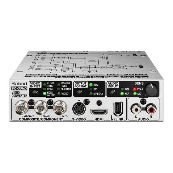
Page 14: Names Of Things And What They Do
Names of Things and What They Do Front Panel fig.front-panel.eps 3. AUDIO INPUT indicators For information on button operations, refer to These set and display the audio source. “Button operations” (p. 17). Use the button to switch the audio source. For information on source and output-format settings, refer to “Converting Signals”... -
Page 15: Hdmi Connector
Connect an i.LINK source here. * If you plan on connecting a video deck or a computer to capture the output of the VC-30HD, use the rear i.LINK connector. The front i.LINK connector is reserved for i.LINK input sources only. -
Page 16: Rear Panel
Names of Things and What They Do Rear Panel fig.rear-panel.eps 1. POWER switch 5. AUDIO IN selector switch This turns the VC-30HD’s power on and off. This switches the mode of the AUDIO IN connectors. • ANALOG 2. DC IN connector... -
Page 17: About Button Operations
Names of Things and What They Do About Button Operations The buttons switch the modes for [VIDEO INPUT], [OUTPUT FORMAT], and [AUDIO INPUT]. If the buttons are difficult to press, use a pen tip or the like to press them. Check the current mode. -
Page 18: Connecting External Equipment
Connecting External Equipment You can connect external equipment as shown below. * To prevent malfunction and/or damage to other devices, always turn off the power on all devices before making any connections. fig.connection-example.eps This unit is equipped with balanced XLR type jacks. Wiring diagrams for these jacks are shown below. -
Page 19: Connecting Video Sources
Connecting External Equipment Connecting Video Sources Use appropriate cables and plugs to connect your video sources. For information on source selection, refer to “Converting Analog Input” (p. 26). Making a Component Connection When making a component connection, use all three [COMPOSITE/COMPONENT] connectors. -
Page 20: Making A Composite/S-Video Connection
Connecting External Equipment Making a Composite/S-Video Connection Making a Composite Connection Connect composite output from a video camera or video mixer to the [COMPOSITE/ COMPONENT] connector on the front panel. * When making a composite connection, use only the [VIDEO/Y] connector. * When BNC/RCA conversion is needed, use an adapter plug. -
Page 21: Making An Hdmi Connection
Connect a video camera or other device provided with HDMI output to the [HDMI] connector on the front panel. For information on the source selection, refer to “Converting HDMI Input” (p. 27). HDCP (High-bandwidth Digital Content Protection) is not supported for HDMI input on the VC-30HD. fig.HDMI-connection.eps Making an i.LINK Connection Connect a video camera or other device provided with i.LINK output to the [i.LINK]... -
Page 22: Connecting Audio Sources
Making an XLR Connection Connect analog output from an audio mixer such as the Roland V-Mixer to the [AUDIO IN] connectors on the rear panel. fig.connect-M300.eps At this time, use the AUDIO IN selector switch to select [ANALOG]. -
Page 23: Making A Digital Connection
Use [AES/EBU] connector on the rear panel for your digital audio source. For information on the source selection, refer to “Audio Source Settings” (p. 28). * The standard supported by the VC-30HD is AES3 (16 to 24 bits, 32 to 48 kHz, 2 channels). fig.connect-AES-EBU.eps At this time, set the [AUDIO IN] selector switch to [AES/EBU TIMECODE]. -
Page 24: Connecting Output Equipment
A short while after making the connection, communication between the VC-30HD and the computer starts, and the standard driver for the operating system is loaded. The VC- 30HD is recognized as a USB video device or audio device. -
Page 25: Connecting A Timecode Source
You can input a timecode from a source device simultaneously with digital audio. Use an XLR cable to connect the source device to the [TIMECODE] connector on the rear panel. * The standard supported by the VC-30HD is SMPTE 12M (LTC). fig.connect-TC-source.eps Audio At this time, use the [AUDIO IN] selector switch to select [AES/EBU TIMECODE]. -
Page 26: Converting Signals
Converting Signals Signals input to the VC-30HD are output from the i.LINK connector and USB connector on the rear panel. Use the button at [OUTPUT FORMAT] to select the output format. The VC-30HD does not support up/down scalling, interlace/progressive (I/P) conversion, or frame- rate conversion. -
Page 27: Converting Hdmi Input
30HD. i.LINK Thru-Out When two i.LINK devices cannot communicate (such as two computer i.LINK ports), you can connect them using the VC-30HD. In this case, you use [VIDEO INPUT] to select [i.LINK THRU]. fig.iLINK-thuru.eps Depending on the i.LINK device, in rare instances, the audio may contain noise, or the picture may... -
Page 28: Audio Source Settings
Converting Signals Audio Source Settings Use the button in the [AUDIO INPUT] section on the front panel and the selector switch on the rear panel to select the audio source. Possible selections are shown below. fig.audio-source-select.eps [RCA] + [ANALOG] The [AUDIO (L/R)] connectors on the front panel are enabled. [RCA] + [AES/EBU TIMECODE] The [AUDIO (L/R)] connectors on the front panel are enabled. -
Page 29: Appendices
Appendices Main Specifications fig.specification-e1.eps Codec MPEG-2 Video, 8 bits, 4:2:0 Video Format 1440 x 1080/59.94i, 50i, 23.98p (25Mbps) 1280 x 720/59.94p, 50p (18.3Mbps) 720 x 480/59.94p, 720 x 576/50p (18Mbps) Audio Format MPEG-1 Audio Layer 2, 16 bits/48kHz, 2ch (384Kbps) Video Format 720 x 480/59.94i (NTSC), 720 x 576/50p (PAL) Audio Format... - Page 30 Appendices fig.specification-e2.eps Input Connectors and Signals i.LINK Connector 6 pins type (S100) x 1 (front) Video Format HDV, DV (IEC61883-2), MPEG-2 TS (IEC61883-4) Max Bit Rate 50 Mbps Analog Connector RCA pin type x 1 pair (L/R) Audio Signal Level -20 to -6 dBu (front) Impedance...
-
Page 31: About Remote Control
USB output to the connected computer is possible even while receiving remote control from the computer. You can select the output bit rate of VC-30HD from your computer from below using this dedicated remote control software. By default, the output bit rate is set to 25 Mbps. -
Page 32: Dimensions
Appendices Dimensions fig.dimension.eps Unit : mm * When using the holes in the side panel to secure the unit in place, use screws measuring 3 mm in diameter and whose length is no more than 8 mm from the surface of the side panel. -
Page 33: Troubleshooting
Use a connection cable that does not contain a resistor. Cannot input from an i.LINK device Has communication been established between the VC-30HD and the i.LINK source device? Input from i.LINK equipment is not possible unless communication has been established. -
Page 34: Radio Frequency Interference Statement
Cet appareil num rique de la classe B respecte toutes les exigences du R glement sur le mat riel brouilleur du Canada. For C.A. US ( Proposition 65 ) WARNING This product contains chemicals known to cause cancer, birth defects and other reproductive harm, including lead. VC-30HD Video Converter... - Page 35 For EU Countries For China...
Need help?
Do you have a question about the VC-30HD and is the answer not in the manual?
Questions and answers