Table of Contents
Advertisement
Quick Links
Owner's Manual
Before using this unit, carefully read the sections entitled "USING THE UNIT
SAFELY" (p. 3) and "IMPORTANT NOTES" (p. 6). These sections provide important
information concerning the proper operation of the unit. Additionally, in
order to feel assured that you have gained a good grasp of every feature of
your new unit, read Owner's Manual in its entirety. This manual should be
saved and kept on hand as a convenient reference.
Copyright © 2013 ROLAND CORPORATION
All rights reserved. No part of this publication may be reproduced in any form without the
written permission of ROLAND CORPORATION.
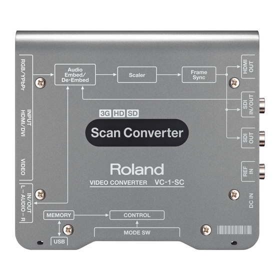
Scan Converter
Advertisement
Table of Contents

Subscribe to Our Youtube Channel
Related Manuals for Roland VC-1-SC


Summary of Contents for Roland VC-1-SC
- Page 1 Owner’s Manual in its entirety. This manual should be saved and kept on hand as a convenient reference. Scan Converter Copyright © 2013 ROLAND CORPORATION All rights reserved. No part of this publication may be reproduced in any form without the written permission of ROLAND CORPORATION.
- Page 2 For the U.K. IMPORTANT: THE WIRES IN THIS MAINS LEAD ARE COLOURED IN ACCORDANCE WITH THE FOLLOWING CODE. BLUE: NEUTRAL BROWN: LIVE As the colours of the wires in the mains lead of this apparatus may not correspond with the coloured markings identifying the terminals in your plug, proceed as follows: The wire which is coloured BLUE must be connected to the terminal which is marked with the letter N or coloured BLACK.
-
Page 3: Using The Unit Safely
Otherwise, you risk causing malfunction. the unit toppling over or dropping down. Do not repair or replace parts by yourself Refer all servicing to your retailer, the nearest Roland Service Center, or an authorized Roland distributor, as listed on the “Information.”... - Page 4 Doing so Do not use overseas may cause short circuits, faulty operation, or other malfunctions. Before using the unit in overseas, consult with your retailer, the nearest Roland Service Center, or an authorized Roland distributor, as listed on the “Information.”...
- Page 5 USING THE UNIT SAFELY CAUTION CAUTION Place in a well ventilated location Disconnect all cords/cables before moving the unit The unit and the AC adaptor should be located so their location or position does Before moving the unit, disconnect the not interfere with their proper power plug from the outlet, and pull out ventilation.
-
Page 6: Important Notes
• Noise may be produced if wireless communications content may be impossible. Roland assumes no devices, such as cell phones, are operated in the liability concerning the restoration of any stored vicinity of this unit. - Page 7 Technology Properties Limited (TPL). Roland has licensed this technology from the TPL Group. • Roland is an either registered trademark or trademark of Roland Corporation in the United States and/or other countries. • Company names and product names appearing in this document are registered trademarks or trademarks of their respective owners.
-
Page 8: Check The Included Items
Check the Included Items The following items are included. Please make sure that all items are present. If anything is missing, please contact your dealer. VC-1-SC itself Owner’s Manual AC adaptor and power cord Rubber feet * The rubber feet are arranged onto one pad. -
Page 9: Table Of Contents
Contents USING THE UNIT SAFELY ....................IMPORTANT NOTES ........................ Check the Included Items ....................About the Power Supply ..................... Connecting the AC Adaptor................... About Securing the Power Cord................. Turning the Power On and Off................About AUTO OFF...................... -
Page 10: About The Power Supply
When the unit is grounded, a slight hum may occur, depending on the particulars of your installation. If you are unsure of the connection method, contact the nearest Roland Service Center, or an authorized Roland distributor, as listed on the “Information” leaflet. Unsuitable places for connection •... -
Page 11: About Securing The Power Cord
About the Power Supply About Securing the Power Cord You can use either of the two methods described below to secure the power cord in place. Doing this can prevent inadvertent disruption of power to your unit (should the plug be pulled out accidentally) and avoid applying undue stress to the DC IN jack. -
Page 12: Turning The Power On And Off
Turn on the power to the VC-1-SC. Inserting the power cord starts the VC-1-SC. Turn on the power to external equipment. Turn on the power to the external devices connected to the VC-1-SC. Turning the power off Turn off the power to external equipment. -
Page 13: Panel Descriptions
Panel Descriptions Front Panel For information on what the colors and the lighted and flashing states of the indicators mean, refer to “Indicator Colors/Operation” (p. 16). RGB/YPbPr INPUT connector/indicator Connect RGB signals from a computer, analog-component signals from a video camera, or other such equipment. -
Page 14: Rear Panel
Panel Descriptions Rear Panel DC IN jack/indicator Connect the included AC Adaptor. The indicator lights up when the VC-1-SC is receiving power. REF IN connector/indicator Connect a clock source device for synchronization. * It is possible to use this unit as a frame synchronizer when supported sync signal is input. -
Page 15: Side Panel
* If the switch is difficult to press, use the tip of a pen or other narrow object to press it. Mode switches (MODE SW) These set the VC-1-SC’s operation mode. Refer to “Setting the Operation Mode” (p. 25). * Use the tip of a pen or similar object to change the setting of a switch. -
Page 16: Indicator Colors/Operation
Panel Descriptions Indicator Colors/Operation SDI IN/OUT SD-SDI input/output Orange HD-SDI input/output Green 3G-SDI input/output Lighted Proper input SDI IN Flashing Input connector selected (no input) Lighted Proper output SDI OUT Flashing Cannot output properly HDMI IN/OUT RGB input/output Orange YCC 444 input/output Green YCC 422 input/output Cannot input/output properly because of no HDCP support... - Page 17 Panel Descriptions RGB/YPbPr IN RGB input Green YPbPr input Lighted Input connector selected (no input) Unlighted Input connector unselected VIDEO IN Lighted Signal input Flashing Input connector selected (no input) Unlighted Input connector unselected...
-
Page 18: About Input/Output Formats
About Input/Output Formats Input Formats RGB/YPbPr IN connector 1920 x 1080 60p, 59.94p, 50p, 60i, 59.94i, 50i, 24PsF, 23.98PsF 1280 x 720 60p, 59.94p, 50p YPbPr 720 x 480 59.94p, 59.94i 720 x 576 50p, 50i 640 x 480 60, 72, 75, 85 Hz 800 x 600 56, 60, 72, 75, 85 Hz 1024 x 768... - Page 19 Audio Linear PCM, 24 bits/48 kHz, 8 channels * The VC-1-SC supports HDCP (High-bandwidth Digital Content Protection system). When an HDCP-applied signal is input, output is possible from only the HDMI OUT connector. Output from the SDI OUT connector and AUDIO OUT connectors is stopped.
-
Page 20: Output Formats
About Input/Output Formats Output Formats SDI OUT connectors 1920 x 1080 59.94p, 50p, 59.94i, 50i 1280 x 720 59.94p, 50p Video 720 x 487 59.94i 720 x 576 Audio Linear PCM, 24 bits/48 kHz, 2 channels HDMI OUT connector 1920 x 1080 59.94p, 50p, 59.94i, 50i 1280 x 720 59.94p, 50p... -
Page 21: Connecting External Equipment
Connecting External Equipment For information on operation modes refer to “Setting the Operation Mode” (p. 25). Connecting Source Equipment Connecting SDI equipment Connect a video camera or other device capable of SDI output to the SDI IN connector. Connecting HDMI equipment Connect a video camera or other device capable of HDMI output to the HDMI INPUT connector. - Page 22 Connecting External Equipment Connecting RGB equipment Connect a computer or other equipment capable of RGB output to the RGB/YPbPr INPUT connector. Connecting component equipment Using a conversion cable, connect equipment capable of component output to the RGB/YPbPr INPUT connector. Female connector ----------- ----------- 1 : Pr...
-
Page 23: Connecting Output Equipment
Connecting External Equipment Connecting a clock source Connect a clock source to the REF IN connector. The VC-1-SC supports the following external clocks. • Black burst • Bi-level/Tri-level synchronization Never input a signal that includes video. Doing so might cause synchronization to be lost. -
Page 24: Connecting A Computer For Remote Control
Connecting a Computer for Remote Control Connect a computer for remote control to the USB port. * Operating the VC-1-SC by remote control requires downloading of the dedicated software (VC-1 RCS) and installing it on a computer. You can download the dedicated software from the following Roland website. -
Page 25: Setting The Operation Mode
Setting the Operation Mode Use the mode switches (MODE SW) on the side panel to set the operation mode of the VC-1-SC. By default, only switch 10 is set to “ON. ” Before making any setting changes, first set switch 10 to “OFF. ”... - Page 26 Setting the Operation Mode MODE SW 5 This specifies the frame rate of output. 59.94 Hz 50 Hz MODE SW 6/7 This specifies the output resolution. Output at SD resolution Output at 1280 x 720 progressive resolution Output at 1920 x 1080 interlaced resolution Output at 1920 x 1080 progressive resolution MODE SW 8 This specifies the setup level for composite input and SD component input.
-
Page 27: Appendices
Appendices Main Specifications Input/Output formats Refer to “About Input/Output Formats” (p. 18). Input connectors BNC type x 1 (combined use with one output connector) HDMI/DVI Type A (19 pins) x 1 RGB/YPbPr 15-pin mini D-Sub type x 1 VIDEO RCA phono type x 1 AUDIO RCA phono type x 1 pair (L/R) (combined use with output jacks) Output connectors... - Page 28 Appendices Signal level/impedance Nominal Input Level -6 dBV Analog Audio Maximum Input Level +6 dBV Input Impedance 22 kΩ Reference (REF IN) Output Impedance 75 Ω Others Power Supply DC 9 V (AC Adaptor) Power Consumption 18 W 150 (W) x 130 (D) x 30 (H) mm Dimensions 5-15/16 (W) x 5-1/8 (D) x 1-3/16 (H) inches 500 g...
-
Page 29: Dimensions
Appendices Dimensions Unit: mm... -
Page 30: Troubleshooting
No audio from the HDMI IN connector is output. Does the connected HDMI source device support linear PCM output? The VC-1-SC supports linear PCM at only 48 kHz. Accordingly, if a different format is input, audio might not be output. -
Page 31: Radio Frequency Interference Statement
For the USA DECLARATION OF CONFORMITY Compliance Information Statement Model Name : VC-1-SC Video Converter Type of Equipment : Responsible Party : Roland Systems Group U.S. Address : 5100 S.Eastern Avenue, Los Angeles, CA 90040-2938, U.S.A. (323) 890 3700 Telephone :... - Page 32 For EU Countries For China...
Need help?
Do you have a question about the VC-1-SC and is the answer not in the manual?
Questions and answers