Seaward Apollo 400 Operating Instructions Manual
Hide thumbs
Also See for Apollo 400:
- Manual (33 pages) ,
- How to configure (3 pages) ,
- How to update firmware (3 pages)
Table of Contents
Advertisement
Quick Links
Advertisement
Table of Contents

Related Manuals for Seaward Apollo 400


Summary of Contents for Seaward Apollo 400
-
Page 1: Operating Instructions
Apollo Operating Instructions Apollo Operating Instructions Bracken Hill South West Industrial Estate Peterlee County Durham SR8 2SW Co Durham SR8 2SW England Tel: (+44) 191 5863511 Part Number 380A5531 Revision 2 November 2015 © 2015 Seaward Electronic Ltd... -
Page 2: Table Of Contents
5. Safety Notes ....................6 6. Accessories ....................7 6.1 Standard Accessories ................7 6.2 Optional Accessories ................7 7. Introduction to the Apollo 400 ..............8 8. Getting Started .................... 8 8.1 Charging New Batteries ................. 8 8.2 Power On ....................8 9. - Page 3 15. Environmental Conditions ................ 27 16. Maintenance .................... 27 16.1 Charging the battery pack..............27 16.2 Securing the Apollo 400 ..............27 16.3 Cleaning the Apollo 400 ..............27 16.4 Replacing the battery pack..............28 17. Support ....................28...
-
Page 4: Limited Warranty & Limitation Of Liability
Operating Instructions 1. Limited Warranty & Limitation of Liability SEAWARD Electronic Limited guarantees this product to be free from defects in material and workmanship under normal use and service for a period of 2 years (subject to product registration) provided that the instrument is serviced and calibrated by a Seaward approved agent in accordance with the manufactures instructions. -
Page 5: Certificate Of Conformity
Performance: The instrument operates within specification when used under the conditions in the above standards EMC and Safety Standards. The product identified above conforms to the requirements of Council Directive 89/336/EEC and 73/23 EEC. Seaward Electronic Ltd is registered under BS EN ISO9001:2000 Certificate No: Q05356. -
Page 6: User Notes
4. User Notes These operating instructions are intended for the use of adequately trained personnel. The following symbols are used in these operating instructions and on the Apollo 400. Warning of electrical danger! Indicates instructions must be followed to avoid danger to persons. -
Page 7: Accessories
Do not open the Apollo 400, no user serviceable parts. Where safe operation of the Apollo 400 is no longer possible it should be immediately shut down and secured to prevent accidental operation. It must be assumed that safe operation is no longer possible:... -
Page 8: Introduction To The Apollo 400
8. Getting Started 8.1 Charging New Batteries Before using Apollo 400 for the first time please ensure that you fully charge the unit using the Seaward black power lead plugged into the mains inlet socket on the top of the tester. -
Page 9: User Interface Navigation
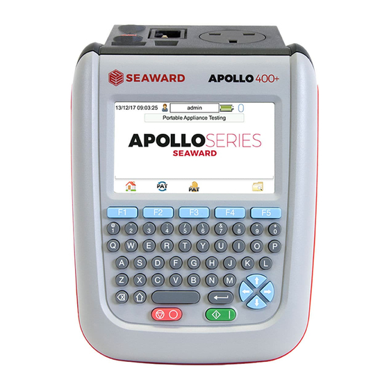
Apollo Operating Instructions 9. User Interface Navigation 9.1 Screen Layout 1. Information bar 2. Function key icons 3. Test interface sequence table 4. Test interface details 5. Main area Information Bar This area of the screen shows the Date, Time, Current User, Battery Status and Connection Status. -
Page 10: Battery Status
9.3 Battery Status While the Apollo 400 is powered on there are periodic checks of the batteries. The Apollo 400 will show the status of the batteries This symbol indicates that the batteries are at 100% capacity. -
Page 11: Main Menu
10.1 View Saved Data This will allow you to view any data that you have saved in the Apollo 400. By selecting this icon in the Main Menu you can view a list of all saved Asset IDs by site and location. -
Page 12: Bluetooth Setup
10.3 Bluetooth Setup Select this icon to setup your Bluetooth accessories to work with the Apollo 400. Switch on the Bluetooth device you wish to pair with and ensure it is discoverable. This will Bluetooth Search button will search the area for Bluetooth discoverable devices and return to the previous menu. -
Page 13: Download
You then need to select one of 2 options from the using dropdown: USB-PC cable Connect the USB download cable to the USB type B port on the Apollo 400 and to a USB port on your PC. Press Save. -
Page 14: Portable Appliance Testing
11. Portable Appliance Testing 11.1 Automatic Test Sequence The Apollo 400 comes with a number of pre-defined test sequences (see Factory Set Test Sequences). These test sequences can include any combination of electrical tests. These test sequences are performed on equipment to ensure that it meets the safety requirements outlined in the IET Code of Practice for In-service Inspection and Testing of Electrical Equipment. -
Page 15: The Electrical Tests
Notes screen by default but this can be changed, see 11.5 PAT Settings. 11.1.4 Printing a Label If you have a TnT Bluetooth printer configured with the Apollo 400 you can print a label after each test. See 10.3 Bluetooth Settings to set up a printer. -
Page 16: Test Functions
Apollo Operating Instructions 11.3 Test Functions Earth Continuity Always ensure that the circuit under test is electrically isolated. Note that measurements can be adversely affected by parallel resistances of additional circuits or by transient currents. Connecting a test probe to a hazardous voltage when a point to point measurement is active will result in that voltage being present on the other test probe. -
Page 17: Nulling Out The Earth Continuity Test Lead(S) Resistance
The feature can be used with both the EUT Continuity and Point to Point measurement modes. The null facility remains active, even if the Apollo 400 is powered off, until the feature is deactivated by pressing the null key again or the Test Type is changed e.g. if a pair of test leads are nulled for point to point measurement, the null will be deactivated if the Test Type is changed to EUT Continuity test. - Page 18 Apollo Operating Instructions insulation resistance between two test probes – Point to Point Insulation to ensure that the test points are adequately insulated from one another. The measurement is displayed in MOhms. There are three possible connection methods for the Insulation test. Insulation The test is performed between the EUT test socket live and neutral and the EUT...
-
Page 19: Substitute Leakage
Apollo Operating Instructions Select Insulation Resistance (2) and press the setup key (F3). In the Test Type field, select the required test. During automatic sequences, the test type will be as per the test type programmed in the test sequence. In manual mode once the correct connections have been made for the selected test type press the Start button, in automatic mode the test will proceed automatically. -
Page 20: Protective Earth (Pe) Conductor Current
Failure to do so may result in incorrect measurements being recorded. This test is applicable on Class I Equipment. The Apollo 400 should be connected to a mains supply. The EUT should be connected into the EUT test socket. In manual mode once the correct... -
Page 21: Rcd Trip Time
Start button. The RCD will be powered and you will be prompted to reset the RCD. When you have reset the RCD the Apollo 400 will count down and then perform the RCD test, the RCD trip time will be displayed. The measurement will be displayed in milli seconds. -
Page 22: Checkbox Verification
EUT. 11.4 Checkbox Verification A checkbox for the Apollo 400 is available as an optional accessory. This can be used to verify that the Apollo 400 test functions are working correctly. When selecting the Checkbox function follow the onscreen instructions. -
Page 23: Electrical Specification
Apollo Operating Instructions 13. Electrical Specification Earth Continuity Output Current (Load 2Ω ): +/- 200mA DC with ZAP Test Voltage (o/c) : > 4VDC 0.05 Ω– 19.99 Ω Measuring Range: 0.01 Ω – 19.99 Ω Display Range: 0.01 Ω Resolution: Operating Error: +/-5% + 4 counts Number of tests as per IEC61557-... - Page 24 Apollo Operating Instructions Load Power/Current Test Voltage: Supply Voltage, maximum load current 16A Display Range: 0.00 - 16.00A Measurement Range: 0.50 - 16.00A Resolution: 0.01A Operating Error: +/-10% of reading +/- 5 digits Lead Test Test Voltage: 5V DC nominal Test: Live / Neutral checks for o/c, s/c and crossed...
-
Page 25: Useful Information
Apollo Operating Instructions 14. Useful Information - 14.1 Factory Set Test Sequences PE Conductor Substitute Visual Earth Continuity Insulation Touch Current Wiring Trip Current Leakage Test Time Duration Limit Limit Duration Limit Duration Limit Duration Limit Limit Duration (s) Voltage (ΩΩ... -
Page 26: Other Information
Apollo Operating Instructions 14.2 Other Information Parameter Default Earth Continuity P/F limit (Ω ) 0.01 19.99 Earth Continuity Duration (s) Insulation Resistance P/F limit (MΩ ) 0.01 19.99 Insulation Resistance Duration (s) Substitute Leakage P/F limit (mA) 0.75 0.25 Substitute Leakage Duration (s) IEC Cord Earth Continuity P/F limit (ohms) 0.01... -
Page 27: Environmental Conditions
16. Maintenance 16.1 Charging the battery pack. The battery pack will be charged whenever the Apollo 400 is connected to the mains supply regardless of whether it is switched on or off. The typical charging current is set to 500mA but this may vary as the instrument also includes pre-charge and top up charge modes. -
Page 28: Replacing The Battery Pack
ONLY USE A REPLACEMENT BATTERY PACK THAT HAS BEEN SUPPLIED BY SEAWARD OR A SEAWARD APPROVED DISTRIBUTOR. 17. Support The Apollo 400 must be registered with Seaward before support will be made available. For Technical Support contact: Tel: (+44) 191 587 8718... - Page 29 Apollo Operating Instructions 17.1 Register your product here:- www.seaward.co.uk 17.2 Calibration Services www.calibrationhouse.co.uk Bracken Hill South West Industrial Estate Peterlee County Durham SR8 2SW Co Durham SR8 2SW England Tel: (+44) 191 5863511 Some icons provided by Fat Cow (http://www.fatcow.com/free-icons/)
- Page 30 Point to point testing* (earth continuity and insulation resistance) makes data management easy and efficient. Insulation resistance IEC lead test The Apollo 400 is ideal for mid-volume PAT testing where detailed records are Protective conductor current required. Touch current Load power/current...
- Page 31 Apollo 400 simple to grasp. Lightweight and small in size, with battery or mains power modes, the Apollo 400 is good to go in seconds; allowing more appliances to be tested without downtime for boot-up or a battery re-charge.
- Page 32 Greater efficiency through useful accessories As with many Seaward PAT testers, the Apollo 400 is compatible with a range of printers and barcode scanners, further speeding up the process of asset recognition, testing and labelling. Optional accessory bundles available:...
- Page 33 Apollo Series Comparison Chart Apollo 400 Apollo 500 Apollo 600 Battery & mains powered Colour Screen & QWERTY keypad 2000 records 10,000 records 50,000 records Large internal memory Scanner & printer compatible Password controlled user accounts General Features Set up multiple user accounts with varying...
-
Page 34: Technical Specifications
Apollo 400 standard package 380A920 Apollo 400 with Elite accessory bundle 380A978 for high loads. Apollo 400 with Elite accessory bundle & PATGuard 3 one year licence Display Range: 0.00kVA – 4.00kVA 380A979 0.00A –...
Need help?
Do you have a question about the Apollo 400 and is the answer not in the manual?
Questions and answers