
Related Manuals for Seaward HALO II


Summary of Contents for Seaward HALO II
- Page 1 HALO II Hook-On Ammeter Operating Instructions Bracken Hill, South West Industrial Estate, Peterlee, Co. Durham. SR8 2SW. England. Tel: +44 (0)191 586 3511 Fax: +44 (0)191 586 0227 www.seaward.co.uk sales@seaward.co.uk service@seaward.co.uk...
- Page 2 HALO II Operating Instructions Limited Warranty & Limitation of Liability SEAWARD Electronic Limited guarantees this product for a period of 1 year. The period of warranty will be effective at the day of delivery. © Copyright 2003 All rights reserved. Nothing from this edition may be...
- Page 3 HALO II Operating Instructions Disposal of Old Product This product has been designed and manufactured with high quality materials and components that can be recycled and reused. When the crossed out wheelie bin symbol is attached to a product it means the product is covered by the European Directive 2002/96/EC.
-
Page 4: Table Of Contents
User Notes These operating instructions are intended for the use of competent personnel. The HALO II hook on ammeter has been designed to make measurements in a dry environment. The following symbols are used in these operating instructions and on the HALO II. -
Page 5: Safety Notes
HALO II Operating Instructions Safety Notes The HALO II hook on ammeter has left the factory in a perfectly safe state. To maintain this state and ensure safe operation of the unit, all notes and warnings in these instructions must be observed at all times. -
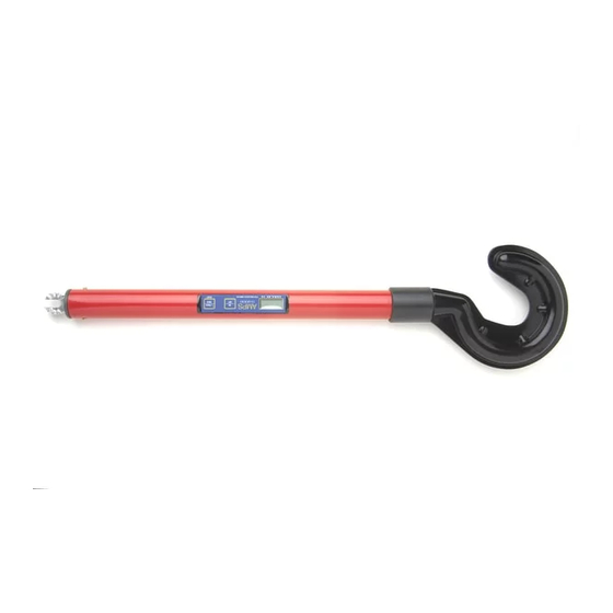
Page 6: Description
3.5” LCD display module. A membrane type tactile response control panel allows an operator to switch the HALO II On / Off and select between Hold and Track modes. Hold Mode allows the display to store the peak reading of the R.M.S. -
Page 7: Electrical Specifications
Battery 9VDC Alkaline MN1604 6LR61 Operation Press and release the On / Off button on the HALO II control panel. If a battery symbol appears on the LCD display then the battery within the unit must be replaced (see section 6). -
Page 8: Battery Installation And Replacement
Using a new battery the HALO II can monitor a conductor current for approximately 30 hours before the battery needs replacing. For best results the hook of the HALO II should be positioned such that it faces away from any other energised line conductor. -
Page 9: Maintenance
HALO II must be appropriately secured to prevent any further use. Cleaning Clean the external case of the HALO II with a clean dry cloth. Avoid using solvents and abrasive scouring agents to clean the external case of the HALO II. - Page 10 205A551 Rev 2...
Need help?
Do you have a question about the HALO II and is the answer not in the manual?
Questions and answers