Table of Contents
Advertisement
Quick Links
Advertisement
Table of Contents

Related Manuals for Vacon nxp/c


Summary of Contents for Vacon nxp/c
- Page 1 ® ac drives user manual...
-
Page 3: Table Of Contents
Power ratings........................15 4.1.1 Vacon NXC – Mains voltage 380-500 V ..............15 4.1.2 Vacon NXC low harmonic drives – Mains voltage 380-500 V .......16 4.1.3 Vacon NXP/C 6 – Mains voltage 500-690 V............17 4.1.4 Vacon NXC low harmonic drives – Mains voltage 525-690 V .......18 Technical data ........................19... - Page 4 • 2 6.2.5 Control cable ......................44 6.2.6 Cable and fuse sizes, 380-500 V units..............45 6.2.7 Cable and fuse sizes, 500/525-690 V units............48 LOW HARMONIC CABINET DRIVE ..............51 NXC Low-Harmonic Cabinet Pre-Charging and MCCB Operating Instructions....51 7.1.1 Manual operation (MAN)..................52 7.1.2...
- Page 5 9. Follow the commissioning instructions, see Chapter 10. 10. The Vacon NX_ Frequency Converter is now ready for use. Vacon Plc is not responsible for the use of the frequency converters against the instructions. 24-hour support +358 (0)201 212 575 • Email: vacon@vacon.com...
-
Page 6: Safety
Do not perform any measurements when the frequency converter is connected to the mains. 13006.emf Do not perform any voltage withstand tests on any part of Vacon NX. There is a certain procedure according to which the tests shall be performed. Ignoring this procedure may result in damaged product. -
Page 7: Safety Instructions
9000.emf The motor terminals U, V, W and the DC-link/brake resistor terminals –/+ and all other mains devices are potentially live when Vacon NX is connected to mains, even if the motor is not running. 9000.emf After disconnecting the frequency converter from the mains, wait until the fan stops and the indicators on the keypad go out (if no keypad is attached see the indicators on the cover). -
Page 8: Running The Motor
13006.emf NOTE! You can download the English and French product manuals with applicable safety, warning and caution information from www.vacon.com/downloads. REMARQUE Vous pouvez télécharger les versions anglaise et française des manuels produit contenant l’ensemble des informations de sécurité, avertissements et mises en garde applicables sur le site www.vacon.com/downloads. -
Page 9: Introduction
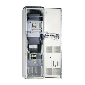
• 7 INTRODUCTION The Vacon NXC is a product range of free standing enclosed frequency converters for the high power range. The NXC is a modular product intended for use in all applications where reliability and high availability is appreciated. -
Page 10: Manufacturer's Declaration Of Conformity
• 8 INTRODUCTION Manufacturer's declaration of conformity Below you can find the Manufacturer's Declarations of Conformity assuring the compliance of Vacon NXP/C frequency converters with the EMC-directives. Tel. +358 (0) 201 2121 • Fax +358 (0)201 212 205... -
Page 11: Receipt Of Delivery
• 9 RECEIPT OF DELIVERY Vacon NX frequency converters have undergone scrupulous tests and quality checks at the factory before they are delivered to the customer. However, after unpacking the product, check that no signs of transport damages are to be found on the product and that the delivery is complete (compare the type designation of the product to the code below). -
Page 12: Nxc Additional Option Codes
• 10 RECEIPT OF DELIVERY NXC additional option codes The NXC enclosure solution contains additional pre-engineered hardware options. These options are appended to the basic type code by using “+” codes. The most common NXC options are listed below: 3.2.1... -
Page 13: General (G-Group)
+DAM Analogue meter (AO1) 48 mm, std scale 0-100% +DCM Analogue meter + current 48 mm, std scale 0-600 A transformer +DVM Analogue vltg meter with sel.switch 0, L1-L2, L2-L3, L3-L1 24-hour support +358 (0)201 212 575 • Email: vacon@vacon.com... -
Page 14: Storage
• 12 RECEIPT OF DELIVERY Storage If the frequency converter is to be kept in store before use make sure that the ambient conditions are acceptable: ° Storing temperature –40…+70 Relative humidity <95%, no condensation The environment should also be free from dust. If there is dust in the air the converter should be well protected to make sure dust does not get into the converter. -
Page 15: Maintenance
RECEIPT OF DELIVERY vacon • 13 Maintenance In normal conditions, Vacon NX frequency converters are maintenance-free. However, we recommend to keep the converter clean, e.g. by cleaning the heatsink with compressed air whenever necessary. In IP54 units, the air filters in the door and in the roof should be cleaned or replaced regularly. -
Page 16: Warranty
(Vacon Warranty Terms). The local distributor may grant a warranty time different from the above. This warranty time shall be specified in the distributor's sales and warranty terms. Vacon assumes no responsibility for any other warranties than that granted by Vacon itself. -
Page 17: Technical Data
(IL) Table 2. Power ratings and dimensions of Vacon NX 6- and 12-pulse drives supply voltage 380-500V Mains voltage 380-500 V, 50/60 Hz, 3~... -
Page 18: Vacon Nxc Low Harmonic Drives - Mains Voltage 380-500 V
(IL) Table 3. Power ratings and dimensions of Vacon low-harmonic drives, supply voltage 380-500V Mains voltage 380-500 V, 50/60 Hz, 3~... -
Page 19: Vacon Nxp/C 6 - Mains Voltage 500-690 V
(IL) Table 4. Power ratings and dimensions of Vacon NX 6- and 12-pulse drives, supply voltage 500—690V Mains voltage 500-690 V, 50/60 Hz, 3~... -
Page 20: Vacon Nxc Low Harmonic Drives - Mains Voltage 525-690 V
(IL) Table 5. Power ratings and dimensions of Vacon low-harmonic drives, supply voltage 525-690V Mains voltage 525-690 V, 50/60 Hz, 3~... -
Page 21: Technical Data
Resolution 0.1% (10-bit), accuracy ±1% Panel reference Resolution 0.01 Hz Field weakening point 8…320 Hz Acceleration time 0.1…3000 sec Deceleration time 0.1…3000 sec Braking DC brake: 30% * T (without brake option); flux braking 24-hour support +358 (0)201 212 575 • Email: vacon@vacon.com... - Page 22 • 20 TECHNICAL DATA Table 6. Technical data Ambient operating tem- –10 °C (no frost)…+40 ºC perature Storage temperature –40 °C…+70 °C Relative humidity 0 to 95% RH, non-condensing, non-corrosive, no dripping water Air quality: chemical vapours IEC 721-3-3, unit in operation, class 3C2...
- Page 23 ** System software version NXP00002V186 (or newer) must be used for the motor thermal memory and memory retention functionality to conform to UL 508C requirements. If an older system software version is used, motor overtemperature protection is required at installation to comply with UL requirements. 24-hour support +358 (0)201 212 575 • Email: vacon@vacon.com...
-
Page 24: Mounting
• 22 MOUNTING MOUNTING Dimensions The table below shows the dimensional drawing of the basic cabinet. It is allowed to install NXC drives side by side. Please note that certain NXC options will further affect the total width or height of the cabinet. - Page 25 * the options +GPL or +GPH (Plinth) increase the height by 100mm or 200mm respectively ** some options, e.g. +CIT (Top input cabling +400mm), +COT (Top output cabling +400mm) and +ODU (output du/dt filter +400mm) affect the width of the cabinet 24-hour support +358 (0)201 212 575 • Email: vacon@vacon.com...
-
Page 26: Lifting The Unit Out Of The Transport Packaging
• 24 MOUNTING Lifting the unit out of the transport packaging The unit is delivered either in a wooden box or a wooden cage. The box may be transported either horizontally or vertically, while transportation of the cage in a horizontal position is not allowed. -
Page 27: Fixing The Unit To The Floor Or To The Wall
In converters consisting of more than one cabinet section, fix all sections in the same way. 11485_00 Figure 4. Fixing the cabinet to the floor and to the wall 24-hour support +358 (0)201 212 575 • Email: vacon@vacon.com... -
Page 28: Fixing To The Floor Only
• 26 MOUNTING 5.3.2 Fixing to the floor only NOTE! This option is not available for FR13 and bigger units. For fixing FR13 and bigger units see delivery specific documentation. If bottom-only fixing is used, additional fixing brackets (Rittal part.nr. 8800.210) or equivalent are necessary. -
Page 29: Ac Choke Connections
NOTE! The NXC low-harmonic drive incorporates an LCL filter instead of AC chokes and this instruction can be ignored. The AC input choke carries out several functions in the Vacon NX 6- and 12-pulse frequency converter. The input choke is needed as an essential component for motor control, to protect the input and DC-link components against abrupt changes of current and voltage as well as to function as a protection against harmonics. -
Page 30: Auxiliary Voltage Transformer Tappings
• 28 MOUNTING Auxiliary voltage transformer tappings NOTE! An auxiliary voltage transformer is always included as standard in NXC low-harmonic drives. If the drive is ordered with an auxiliary voltage transformer for 230V auxiliary voltage supply (+ATx option) the tappings of the transformer have to be set according to the mains voltage. -
Page 31: Cooling
Cooling air required [m 0261—0300 5 1000 0125—0208 6 0385—0520 5 2000 0261—0416 6 0590—0730 5 3000 0460—0590 6 0820—1030 5 4000 0650—0820 6 1300—1450 5 (6-p) 6000 1300—1450 6 (12-p) 7000 24-hour support +358 (0)201 212 575 • Email: vacon@vacon.com... - Page 32 • 30 MOUNTING Table 10. Required cooling air for NXC 6- and 12-pulse drives Type Cooling air required [m 1150 5 5000 0920—1180 6 1500 6 (6-p) 9000 1770—2150 5 10000 1900—2250 6 Table 11. Required cooling air for NXC low-harmonic drives...
-
Page 33: Power Losses
Heat losses of NXC low-harmonic drives are roughly 1,5...2 times more compared to 6-p and 12- pulse. Additional information on heat losses for specific frame size and current class is available on request. 24-hour support +358 (0)201 212 575 • Email: vacon@vacon.com... -
Page 34: Cabling And Connections
• 32 CABLING AND CONNECTIONS CABLING AND CONNECTIONS Understanding the power unit topology Figure 9 and Figure 10 show the principles for mains and motor connections of the basic 6-pulse drive in frame sizes FR10 to FR14. Some units built in frame size FR11 have double input devices and require an even number of supply cables but an uneven number of motor cables can be used. - Page 35 Figure 10. Topology of mechanical sizes NXC low-harmonic drives AF9 – AF14 NOTE! Some options affect the wiring direction and principle for power cables; always check delivery specific documentation for exact information. 24-hour support +358 (0)201 212 575 • Email: vacon@vacon.com...
-
Page 36: Power Connections
-C2.1 -C2.2 -C3.1 -C3.2 -C6.1 -C6.2 11181_emf Figure 11. Vacon LCL filter wiring diagram 6.2.1.1 Removing HF capacitors If a PWM modulated rectifier of another manufacturer is connected to the same input transformer, the capacitors must be removed. Otherwise the capacitors must not be removed. - Page 37 Figure 12. HF capacitors in NXC low-harmonic drive mechanical sizes AF9, AF10 and AF12 LCL filter Remove Remove 11493_uk Figure 13. HF capacitors in NXC low-harmonic drive mechanical sizes AF13-AF14 LCL filter 24-hour support +358 (0)201 212 575 • Email: vacon@vacon.com...
-
Page 38: Mains And Motor Cables
• 36 CABLING AND CONNECTIONS 6.2.2 Mains and motor cables The mains cables are connected to terminals L1, L2 and L3 (12-pulse units 1L1, 1L2, 1L3, 2L1, 2L2, 2L3) and the motor cables to terminals marked with U, V and W, see Figure 15. - Page 39 Table 13 and show the minimum dimensions of Cu- and Al-cables and the recommended aR fuse sizes. If the motor temperature protection of the drive (see Vacon All in One Application Manual) is used as an overload protection, the cable should be chosen accordingly. If three or more cables are used parallelly (per block) in bigger units each cable requires a separate overload protection.
- Page 40 • 38 CABLING AND CONNECTIONS Connect motor cables to terminals U, V and W on Connect mains cables to converter using cable terminals L1, L2 and L3 lugs on the input device (if used] or to power terminals on the...
- Page 41 Connect the PE conductor to the EMC-earthing clamp for PE bar motor cable screen 11498_uk Figure 18. Routing of power cables, bottom cabling, frame AF10 24-hour support +358 (0)201 212 575 • Email: vacon@vacon.com...
- Page 42 • 40 CABLING AND CONNECTIONS Connect Connect mains cables to motor cables terminals L1, L2 and L3 to terminals on AC drive U, V and W on converter Connect the PE conductor to the PE bar 7019.emf Figure 19. Routing of power cables, bottom cabling, frame AF12 +ODU (optional)
- Page 43 Figure 22. To conform to the EMC requirements, a particular cable gland shall be used. The cable glands are designed to be used together with screened cables when electromagnetic compatibility (EMC) is required. 11501_00 Figure 22. Routing of supply and power cables 24-hour support +358 (0)201 212 575 • Email: vacon@vacon.com...
- Page 44 • 42 CABLING AND CONNECTIONS Cable tie Fastening spring Metal sock PE(N) screen Assembly plate Cable Bush ring Rubber sealing 11502_uk Figure 23. Components of the cable gland set Installing the cable gland Unless the cable gland is already installed by the manufacturer, follow the procedure below to do this: Assemble the rubber sealing in the narrow groove of the bush ring.
- Page 45 Vacon's delivery consists of fixed sets of ferrite rings (option). When ferrite rings are used to attenuate the risk of bearing damages, use always two ferrite ring sets per motor cable.
-
Page 46: Thermal Supervision Of Option +Odc
6.2.4 DC supply and brake resistor cables Vacon 6- and 12-pulse frequency converters can optionally be equipped with terminals for DC supply and with an external brake resistor. These terminals are marked with B-, B+/R+ and R-. The DC bus connection is made to terminals B– and B+ and the brake resistor connection to R+ and R–... -
Page 47: Cable And Fuse Sizes, 380-500 V Units
The table below shows typical cable sizes and types that can be used with the converter. The final selection should be made according to local regulations, cable installation conditions and cable specification. 6.2.6.1 6-pulse drives Table 13. Cable and fuse sizes for Vacon NX_5, 6-pulse supply No. of No. of Bussmann/Ferraz Fuse I... - Page 48 • 46 CABLING AND CONNECTIONS 6.2.6.2 12-pulse drives Table 14. Cable and fuse sizes for Vacon NX_5, 12-pulse supply No. of No. of Bussmann / Ferraz Fuse I Mains and motor Frame Type supply motor Shawmut fuse type cable...
- Page 49 CABLING AND CONNECTIONS vacon • 47 6.2.6.3 Low-harmonic drives Table 15. Cable and aR fuse sizes for Vacon NX_5 low-harmonic drive No. of No. of Bussmann/Ferraz Fuse I Mains and motor Frame Type supply motor Shawmut fuse type cable cables...
-
Page 50: Cable And Fuse Sizes, 500/525-690 V Units
The table below shows typical cable sizes and types that can be used with the converter. The final selection should be done according to local regulations, cable installation conditions and cable specification. 6.2.7.1 6-pulse drives Table 16. Cable and aR fuse sizes for Vacon NX_6, 6-pulse supply Mains and motor Bussmann/ No of No of... - Page 51 CABLING AND CONNECTIONS vacon • 49 6.2.7.2 12-pulse drives Table 17. Cable and aR fuse sizes for Vacon NX_6, 12-pulse supply Bussmann Mains and motor No of No of Fuse I Frame Type /Ferraz Shawmut cable supply motor fuse type...
- Page 52 • 50 CABLING AND CONNECTIONS 6.2.7.3 Low-harmonic drives Table 18. Cable and aR fuse sizes for Vacon NX_6 low-harmonic drive Mains and motor No of No of Bussmann / Ferraz Fuse I Frame Type cable supply motor Shawmut fuse type...
-
Page 53: Low Harmonic Cabinet Drive
• REM – Remote operation with signals to the control terminals • AUTO – Automatic operation which automatically pre-charges and closes the MCCB when the supply voltage is energized 11506_00 Figure 25. MCCB Control selector switch (-S6) 24-hour support +358 (0)201 212 575 • Email: vacon@vacon.com... -
Page 54: Manual Operation (Man)
• 52 LOW HARMONIC CABINET DRIVE 7.1.1 Manual operation (MAN) The operator can control the circuit-breaker (MCCB) and the charging circuit manually from the 0–1-Start cabinet while the MCCB control switch –S6 is in position. The switch is used for the local operation of the MCCB and pre-charging circuit. -
Page 55: Remote Operation (Rem)
(terminal name can vary depending on the frame size). The Run command has to be given to the AFE unit from the keypad, I/O signal or bus communication before the inverter INU can be started (operated). 24-hour support +358 (0)201 212 575 • Email: vacon@vacon.com... -
Page 56: Automatic Operation (Auto)
• 54 LOW HARMONIC CABINET DRIVE MCCB Open MCCB Close (Charging pulse) 11509_uk Figure 28. Circuit diagram of remote contacts for the control of the MCCB and pre-charging circuit (NXC low-harmonic FR12) In case of a voltage drop of <0.7xU... -
Page 57: Circuit-Breaker Trip Due To Overload Or Short-Circuit
This will reset the circuit-breaker and, at the same time in FR9, FR10 or FR12 solution, recharge the spring system of the motor operators. After this it is possible to pre-charge and close the circuit-breakers by methods described in previous chapters. 24-hour support +358 (0)201 212 575 • Email: vacon@vacon.com... -
Page 58: Installation Instructions
• 56 INSTALLATION INSTRUCTIONS INSTALLATION INSTRUCTIONS Before starting the installation, check that none of the components of the frequency converter is live. Make sure that the space where the converter is installed, and the converter itself, is clean and free from particles, dust or humidity that could harm the converter when it is powered on. - Page 59 IMPORTANT! If an output filter (+ODU, +ODC or +OSI) is used, note that the switching frequency of the converter (parameter 2.6.9, ID601) must be set according to the specification of the output filter. Setting too high/low a switching frequency may damage the filter. 24-hour support +358 (0)201 212 575 • Email: vacon@vacon.com...
-
Page 60: Cable Installation And The Ul Standards
• 58 INSTALLATION INSTRUCTIONS Cable installation and the UL standards To meet the UL (Underwriters Laboratories) regulations, a UL-approved copper cable with a ° minimum heat-resistance of +60/75 C must be used. The cable must be suitable for use on a circuit capable of delivering not more than 100,000 rms symmetrical amperes, 600V maximum. -
Page 61: Cable And Motor Insulation Checks
Disconnect the brake resistor cable and measure the insulation from the power terminals to the ground terminal. The measurement voltage must equal at least the motor nominal voltage but not exceed 1000 V. The insulation resistance must be >1MΩ. 24-hour support +358 (0)201 212 575 • Email: vacon@vacon.com... -
Page 62: Control Unit
The I/O boards mounted at the factory are indicated in the type code. For more information on the option boards, see Vacon NX option board manual (ud741). The control board can be powered externally (+24 V, ±10%) by connecting the external power source to either of the bidirectional terminala #6 or #12, see page 63. -
Page 63: Control Connections
<2k VA/2 50Vac Co ntin uo us ly: TI1+ <2A rm s TI1- Basic relay board Basic relay board OPT-A2 OPT-A3 11517_uk Figure 35. General wiring diagram of the basic relay boards (OPT-A2/OPT-A3) 24-hour support +358 (0)201 212 575 • Email: vacon@vacon.com... - Page 64 • 62 INSTALLATION INSTRUCTIONS 8.2.1.1 Control cables The control cables shall be at least 0.5 mm screened multicore cables, see Table 12. The maximum terminal wire size is 2.5 mm for the relay terminals and 1.5 mm for other terminals.
-
Page 65: Control Terminal Signals
AO1– Analogue output Voltage 0—10 V, R >1 kΩ common Selection with jumper block X6 (see page 66): Open collector output Maximum U = 48 VDC Maximum current = 50 mA 24-hour support +358 (0)201 212 575 • Email: vacon@vacon.com... - Page 66 • 64 INSTALLATION INSTRUCTIONS Table 22. Control I/O terminal signals on basic relay board OPT-A2 Terminal Signal Technical information OPT-A2 RO1/1 Relay output 1 Switching capacity 24 VDC/8 A 250 VAC/8 A RO1/2 125 VDC/0.4 A RO1/3 Min.switching load...
- Page 67 On the A1 basic board, there are four jumper blocks X1, X2, X3 and X6 each containing eight pins and two jumpers. The selectable positions of the jumpers are shown in Figure 39. 11520_00 Figure 38. Jumper blocks on OPTA1 24-hour support +358 (0)201 212 575 • Email: vacon@vacon.com...
- Page 68 • 66 INSTALLATION INSTRUCTIONS Jum per block X 1 : Jum per block X 2 : AI1 m ode AI2 m ode AI1 mode: 0...20mA; Current input AI2 mode: 0...20mA; Current input AI1 mode: Voltage input; 0...10V AI2 mode: Voltage input; 0...10V AI1 mode: Voltage input;...
-
Page 69: Connecting Power Supply And Internal Control Cables
Fix the cable bundle at two or more points, at least one at each end, to prevent damages to the cables. Fasten the protective cover on the power unit when the work is finished. 24-hour support +358 (0)201 212 575 • Email: vacon@vacon.com... -
Page 70: Optic Fibre Cables, Signal Listing And Connections
• 68 INSTALLATION INSTRUCTIONS Optic fibre cables, signal listing and connections Star coupler board on control unit Terminals on ASIC board of power module 1 Trip signal from power module 1 Gate control enable VaconBus data from ASIC 1 to control board... -
Page 71: Control Keypad
• 69 CONTROL KEYPAD The control keypad is the link between the Vacon frequency converter and the user. The Vacon NX control keypad features an alphanumeric display with seven indicators for the Run status (RUN, , READY, STOP, ALARM, FAULT) and three indicators for the control place (I/O term/ Keypad/ BusComm). -
Page 72: Control Place Indications
• 70 CONTROL KEYPAD 9.1.2 Control place indications The symbols I/O term, Keypad Bus/Comm (see Figure 42) indicate the choice of control place made in the Keypad control menu (M3) (see Chapter 9.3.3). I/O term = I/O terminals are the selected control place; i.e. START/STOP commands or reference values etc. -
Page 73: Keypad Push-Buttons
CONTROL KEYPAD vacon • 71 Keypad push-buttons The Vacon alphanumeric control keypad features 9 push-buttons that are used for the control of the frequency converter (and motor), parameter setting and value monitoring. 11525_00 Figure 43. Keypad push-buttons 9.2.1 Button descriptions = This button is used to reset active faults (see Chapter 9.3.4). -
Page 74: Navigation On The Control Keypad
• 72 CONTROL KEYPAD Navigation on the control keypad The data on the control keypad are arranged in menus and submenus. The menus are used for example for the display and editing of measurement and control signals, parameter settings (Chapter 9.3.2), reference values and fault displays (Chapter 9.3.4). - Page 75 Change 13.95 Hz Browse value RU N R EADY READY I/O te rm I/O term No editing! Monitor Output frequency 13.95 Hz 11527_uk Figure 44. Keypad navigation chart 24-hour support +358 (0)201 212 575 • Email: vacon@vacon.com...
-
Page 76: Monitoring Menu (M1)
• 74 CONTROL KEYPAD 9.3.1 Monitoring menu (M1) You can enter the Monitoring menu from the Main menu by pushing the Menu button right when the location indication M1 is visible on the first line of the display. How to browse through the monitored values is presented in Figure 45. -
Page 77: Parameter Menu (M2)
Once in the last parameter of a parameter group, you can move directly to the first parameter of Browser button up that group by pushing the See the diagram for parameter value change procedure on page 76. 24-hour support +358 (0)201 212 575 • Email: vacon@vacon.com... -
Page 78: Keypad Control Menu (M3)
• 76 CONTROL KEYPAD Keypad Input signals G1 G8 READY READY READY Keypad Keypad Keypad Parameters Basic parameters Min Frequency 13.95 Hz READY READY Keypad Keypad Min Frequency Min Frequency 13.95 Hz 14.45 Hz enter 11529_uk Figure 46. - Page 79 See Figure 47 for how to change the rotation direction. NOTE! Additional information on controlling the motor with the keypad is given in Chapters 9.2.1 and 10.2. 24-hour support +358 (0)201 212 575 • Email: vacon@vacon.com...
-
Page 80: Active Faults Menu (M4)
• 78 CONTROL KEYPAD 9.3.3.4 Stop button activated By default, pushing the STOP button will always stop the motor regardless of the selected control place. You can disable this function by giving parameter 3.4 the value 0. If the value of this parameter is 0, the STOP button will stop the motor only when the keypad has been selected as the active control place. - Page 81 If the drive is unable to restart the motor after an AR fault (Fault Trip) an FT fault occurs. The effect of the 'FT fault' is basically the same as that of the F fault: the drive is stopped. 24-hour support +358 (0)201 212 575 • Email: vacon@vacon.com...
- Page 82 • 80 CONTROL KEYPAD 9.3.4.2 Fault time data record When a fault occurs the information described above in 9.3.4 is displayed. By pushing the Menu button right Fault time data record menu here you will enter the indicated by T.1T.13. In this menu, some selected important data valid at the time of the fault are recorded.
-
Page 83: Fault History Menu (M5)
Operation hours 13:25:43 R EADY READ Y READ Y I/Oterm I/Oterm I/Oterm Operation days Fault history 11 Output phase PUSH to reset enter 11533_uk Figure 49. Fault history menu 24-hour support +358 (0)201 212 575 • Email: vacon@vacon.com... -
Page 84: System Menu (M6)
• 82 CONTROL KEYPAD 9.3.6 System menu (M6) System menu can be entered from the main menu by pushing the Menu button right when the location indication M6 is visible on the display. The controls associated with the general use of the frequency converter, such as application... - Page 85 Info: Power unit type I6.8.5.1 code I6.8.5.2 Info: Unit voltage I6.8.5.3 Info: Brake chopper I6.8.5.4 Info: Brake resistor S6.8.6 Expander boards For Application programming S6.8.7 Debug menu only. Contact factory for more details 24-hour support +358 (0)201 212 575 • Email: vacon@vacon.com...
- Page 86 • 84 CONTROL KEYPAD 9.3.6.1 Language selection The Vacon control keypad offers you the possibility to control the frequency converter through the keypad in the language of your choice. System menu Locate the language selection page under the . Its location indication is S6.1. Press Menu button right once to enter the edit mode.
- Page 87 The parameter copy menu (S6.3) embodies four functions: Parameter sets (S6.3.1) The Vacon NX frequency converter features a possibility for the user to load back the factory default parameter values and to store and load two customised parameter sets (all parameters included in the application).
- Page 88 • 86 CONTROL KEYPAD READY READY enter CONFIRM Parameter sets Parameter sets Select LoadFactDef CANCEL READY READY Parameter sets Parameter sets Wait... 11536_uk Figure 52. Storing and loading of parameter sets Upload parameters to keypad (To keypad, S6.3.2) This function uploads all existing parameter groups to the keypad provided that the drive is stopped.
- Page 89 CONTROL KEYPAD vacon • 87 When the Parameter backup function is activated Vacon NX control keypad makes a copy of the parameters of the presently used application. Every time a parameter is changed the keypad backup is automatically updated. When applications are changed, you will be asked if you wish the parameters of the new application Enter button to be uploaded to the keypad.
- Page 90 • 88 CONTROL KEYPAD 9.3.6.5 Security NOTE! The Security submenu is protected with a password. Store the password in a safe place! Password (S6.5.1) The application selection can be protected against unauthorised changes with the Password function (S6.5.1). By default, the password function is not in use. If you want to activate the function, enter the edit...
- Page 91 11541_uk Figure 57. Activation of Start-up wizard Multimonitoring items (P6.5.4) Vacon alpha-numeric keypad features a display where you can monitor even three actual values at the same time (see Chapter 9.3.1 and Chapter Monitoring values in the manual of the application you are using).
- Page 92 • 90 CONTROL KEYPAD 9.3.6.6 Keypad settings In the Keypad settings submenu under the System menu you can further customise your frequency converter operator interface. Locate the Keypad settings submenu (S6.6). Under the submenu, there are four pages (P#)
- Page 93 Menu button left NOTE! The brake resistor is available as optional equipment for all classes. It can be installed internally in classes FR4 to FR6. 24-hour support +358 (0)201 212 575 • Email: vacon@vacon.com...
- Page 94 • 92 CONTROL KEYPAD READY READY READY I/Ot erm I/Ot erm I/Ot erm HW settings InternBrakeRes System Menu Connected READY READY I/Ot erm I/Ot erm InternBrakeRes InternBrakeRes enter Connected Not conn. 11546_uk Figure 62. Internal brake resistor connection Fan control (P6.7.2)
- Page 95 See Figure 64 for the procedure of changing the value. 9.3.6.8 System info System info submenu In the (S6.8) you can find frequency converter-related hardware and software information as well as operation-related information. Total counters (S6.8.1) 24-hour support +358 (0)201 212 575 • Email: vacon@vacon.com...
- Page 96 • 94 CONTROL KEYPAD Total counters In the page (S6.8.1) you can find information related to the frequency converter operation times, i.e. the total numbers of MWh, operation days and operation hours passed so far. Unlike the counters in the Trip counters, these counters cannot be reset.
- Page 97 Browser buttons and then enter the Information pages Menu button right Browser buttons with the . Use again the to see the different pages. 24-hour support +358 (0)201 212 575 • Email: vacon@vacon.com...
- Page 98 • 96 CONTROL KEYPAD Hardware (S6.8.5) Hardware information page provides information on the following hardware-related topics: Table 34. Hardware information pages Page Content 6.8.5.1 Nominal power of the unit 6.8.5.2 Nominal voltage of the unit 6.8.5.3 Brake chopper 6.8.5.4 Brake resistor Expander boards (S6.8.6)
-
Page 99: Expander Board Menu (M7)
C H AN GE VA L UE Slave address Slave address C ON FIR M CHANGE enter R EA DY I/Oterm Baud rate Auto 11552_uk Figure 68. Expander board information menu 24-hour support +358 (0)201 212 575 • Email: vacon@vacon.com... -
Page 100: Further Keypad Functions
• 98 CONTROL KEYPAD Further keypad functions The Vacon NX control keypad embodies additional application-related functions. See Vacon NX Application Package for more information. Tel. +358 (0) 201 2121 • Fax +358 (0)201 212 205... -
Page 101: Commissioning
(if no keypad is attached see the indicator through the keypad base). Wait 5 more minutes before doing any work on Vacon NX connections. Do not even open the cabinet door or cover before this time has expired. -
Page 102: Commissioning Of The Frequency Converter
5. Check that all Start/Stop switches connected to the I/O terminals are in Stop-position. 6. Connect the frequency converter to mains. 7. Set the parameters of group 1 (See Vacon All in One Application Manual) according to the requirements of your application. At least the following parameters should be set:... - Page 103 10. Connect the motor to the process (if the startup test was run without the motor being con nected). Before running the tests, make sure that this can be done safely. Inform your co-workers of the tests. Repeat test 8A or 8B. 24-hour support +358 (0)201 212 575 • Email: vacon@vacon.com...
-
Page 104: Fault Tracing
• 102 FAULT TRACING FAULT TRACING The fault codes, their causes and correcting actions are presented in Table 37 below. The converter has an internal memory for storing the converter status at the time of fault as well as additional information about the source of the fault. - Page 105 If real time is set to run on the frequency converter the data items T1 and T2 will appear as follows: Date yyyy-mm-dd Time hh:mm:ss, NOTE! When contacting your Vacon partner because of a fault condition, always write down all texts and codes on the keypad display before. 24-hour support +358 (0)201 212 575 • Email: vacon@vacon.com...
-
Page 106: Fault Codes
• 104 FAULT TRACING 11.2 Fault codes The fault codes, their causes and correcting actions are presented in the table below. The shadowed faults are A faults only. The items written in white on black background present faults for which you can program different responses in the application. See parameter group Protections. - Page 107 Decrease the motor load. Motor frequency converter motor temperature If no motor overload exists, check the overtemperature model. Motor is overloaded. temperature model parameters. Motor underload Motor underload protection has tripped. Check load. 24-hour support +358 (0)201 212 575 • Email: vacon@vacon.com...
- Page 108 • 106 FAULT TRACING Table 37. Fault codes Fault Fault Fault Correcting measures code Unbalance between power modules in paralleled units. Unbalance Should the fault re-occur, contact your Subcode in T.14: (Warning only) local distributor. S1 = Current unbalance...
- Page 109 Defective option board or slot. Contact the nearest Vacon distributor. Temperature limit values set for the PT100 board PT100 board parameters have been Find the cause of temperature rise. temp. fault exceeded. 24-hour support +358 (0)201 212 575 • Email: vacon@vacon.com...
- Page 112 Find your nearest Vacon office on the Internet at: www.vacon.com Manual authoring: documentation@vacon.com Document ID: Vacon Plc. Runsorintie 7 65380 Vaasa Finland Subject to change without prior notice Rev. B © 2013 Vacon Plc.
Need help?
Do you have a question about the nxp/c and is the answer not in the manual?
Questions and answers