Table of Contents
Advertisement
S A M L E X
20 Years focused on power inverters
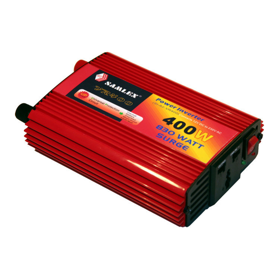
POWER INVERTER
With Advanced Technology!!!
THIS MANUAL CONTAINS IMPORTANT INFORMATION REGARDING
SAFETY, OPERATION, MAINTENANCE AND STORAGE OF THIS
PRODUCT. BEFORE USE, READ AND UNDERSTAND ALL CAUTIONS,
WARNINGS, INSTRUCTIONS AND PRODUCT LABELS, PLUS YOUR
VEHICLE'S BATTERY MANUFACTURER GUIDELINES. FAILURE TO DO
SO COULD RESULT IN INJURY AND/OR PROPERTY DAMAGE.
VR Series
OWNER'S MANUAL
For models:
VR175...... 175W
VR250...... 250W
VR400...... 400W
Advertisement
Table of Contents

Subscribe to Our Youtube Channel
Related Manuals for Samlexpower VR175


Summary of Contents for Samlexpower VR175
- Page 1 S A M L E X 20 Years focused on power inverters VR Series POWER INVERTER OWNER’S MANUAL For models: VR175…… 175W VR250…… 250W VR400…… 400W With Advanced Technology!!! THIS MANUAL CONTAINS IMPORTANT INFORMATION REGARDING SAFETY, OPERATION, MAINTENANCE AND STORAGE OF THIS PRODUCT.
- Page 2 IMPORTANT SAFETY INSTRUCTIONS To ensure reliable service, your power inverter must be installed and used properly. Please read the installation and operating instructions thoroughly prior to installation and use. Pay particular attention to the WARNING and CAUTION statements in this manual. The CAUTION statements advise against certain conditions and practices that may result in damage to your inverter.
-
Page 3: Table Of Contents
CONTENTS 1. INTRODUCTION………………………………………………………4 2. CONTROLS, INDICATORS AND CONNECTORS………………..5 3. HOW YOUR INVERTER WORKS…………………………………..6 3.1 Principle of Operation…………………………………………….6 3.2 The Output Waveform………………………………………….6 4. INSTALLATION/ENVIRONMENTS……………………………….7 4.1 Power Source Requirements…………………………………….7 4.2 Connection to Power Source………………………………….7,8 4.3 Connection to Load………………………………………………9 4.4 Placement of Inverter…………………………………………….9 5. -
Page 4: Introduction
1. INTRODUCTION Your new SAMLEX VR-Series power inverter is one in a series of the most advanced DC to AC inverters available today. With proper care and appropriate usage, it will give you years of dependable service in your car, truck, RV or boat. -
Page 5: Controls, Indicators And Connectors
2. CONTROLS, INDICATORS AND CONNECTORS Figure 1 & 2 detail the front & back panel of the inverter. The front panel provides two LED indicators. A green LED shows proper operation when lit. The red LED shows inverter shutdown from overload, over voltage or over temperature. -
Page 6: How Your Inverter Works
(See Figure 4). The modified sine wave produced by the VR175/VR250/VR400 inverter has an RMS (root mean square) voltage of 230 volts, which is the same as standard household power. -
Page 7: Installation/Environments
Example: lf a load is rated at 100 watts AC, the power source must be able to deliver: 100 divided by 10=10 amperes CAUTION: The SI-A2-VR175/VR250/VR400 must be connected only to batteries with a nominal output voltage of 12 volts. The unit will not operate from a 6 volt battery, and will sustain permanent damage if connected to a 24 volt battery. - Page 8 If the inverter is to be used for extended periods at power levels above 175 watts, direct connection to the power source is required. Use the provided cables to connect the VR250/VR400 directly to the 12 volt power source using the following guidelines: 1.
-
Page 9: Connection To Load
CONNECTION TO LOAD The inverter is equipped with a universal AC power receptacle. Plug the cord from the equipment you wish to operate into the AC receptacle. The green LED indicator lights to indicate that the inverter is functioning. Make sure the combined load requirement of your equipment does not exceed inverter’s output rating. -
Page 10: Operating Tips
5. OPERATING TIPS RATED VERSUS ACTUAL CURRENT DRAW OF EQUIPMENT Most electrical tools, appliances and audio/video equipment have labels that indicate the power consumption in amps or watts. Be sure that the power consumption of the item you wish to operate is rated at 175/250/400 watts or less. -
Page 11: Protective Features Of The Inverter
6. PROTECTIVE FEATURES OF THE INVERTER Your inverter monitors the following potentially hazardous conditions: OVER TEMPERATURE PROTECTION – If the temperature inside the inverter is too high, the unit will automatically shut down. Allow the unit to cool for at least 15 minutes before restarting after a heat-related shutdown. -
Page 12: Common Problems
7. COMMON PROBLEMS “BUZZING” SOUND IN AUDIO SYSTEMS: Some inexpensive stereo systems and “boom boxes” emit a buzzing sound from their speakers when operated from the power inverter. This occurs because the power supply in the electronic device does not adequately filter the modified sine wave produced by the inverter. -
Page 13: Troubleshooting Guide
8. TROUBLESHOOTING GUIDE TABLE 1 – INVERTER POWER SWITCH TURNED ON TROUBLE/ INDICATION POSSIBLE CAUSE SUGGESTED REMEDY No AC output; DC input below 10 volts Recharge or replace battery Red LED lit Green LED not lit Inverter Remove or reduce load, overheat thermal wait for inverter to cool. -
Page 14: Fuse Replacement
9. FUSE REPLACEMENT This inverter is protected by our integral electronic circuit and will automatically reset. More than that, this inverter is equipped with a fuse that is located inside the inverter. Normally, this fuse will not blow unless there is a serious problem occurs.
Need help?
Do you have a question about the VR175 and is the answer not in the manual?
Questions and answers