Asco 7000 Series User Manual
Medium voltage transfer switch
Hide thumbs
Also See for 7000 Series:
- Operator's manual (20 pages) ,
- Installation manual (16 pages) ,
- User manual (32 pages)
Table of Contents
Advertisement
7000 Series Medium Voltage Transfer Switch User Manual
Version
Revision Date
BOM Code
Emerson Network Power provides customers with technical support. Users may contact the nearest
Emerson Network Power sales office or service center.
Copyright © 2016 by Emerson Network Power Co., Ltd.
All rights reserved. The contents in this document are subject to change without notice.
Emerson Network Power Co., Ltd.
Block B2, Nanshan I Park, No.1001 Xueyuan Road, Nanshan District, Shenzhen, 518055, P.R. China
E-mail: customercare@asco.com
V1.0
May 12, 2016
31013291
Advertisement
Table of Contents
Troubleshooting

Related Manuals for Asco 7000 Series


Summary of Contents for Asco 7000 Series
- Page 1 7000 Series Medium Voltage Transfer Switch User Manual Version V1.0 Revision Date May 12, 2016 BOM Code 31013291 Emerson Network Power provides customers with technical support. Users may contact the nearest Emerson Network Power sales office or service center. Copyright © 2016 by Emerson Network Power Co., Ltd.
-
Page 3: Table Of Contents
Contents Chapter 1 Overview ..............................1 1.1 Model Description ............................1 1.2 Appearance ..............................2 1.3 Product Composition ............................2 1.4 Climate classes.............................. 3 Chapter 2 Installation And Operation ..........................4 2.1 Installation ..............................5 2.1.1 Supporting Structure ........................... 5 2.1.2 Mounting ............................. -
Page 5: Chapter 1 Overview
Chapter 1 Overview Chapter 1 Overview The ASCO 7000 Series medium voltage transfer switch meets GB3906 and IEC62271-200 standards. This chapter will introduce the model description, appearance, product composition, and application environment, as well as the mechanical and electrical parameters of this transfer switch. -
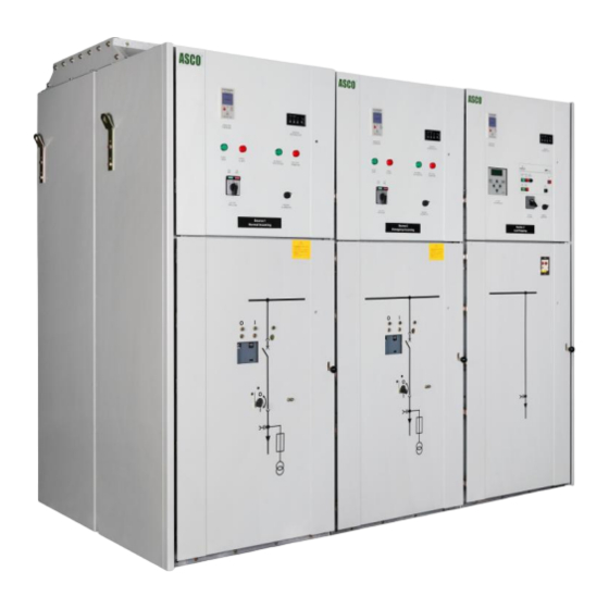
Page 6: Appearance
Circuit Breaker Control Switch Emergency Source Circuit Breaker Normal Source Circuit Breaker ) Figure 1-2 Typical 7000 Series MV ATS with location of major components (1250A, Load section shown on right ASCO 7000 Series Medium Voltage Transfer Switch User Manual... -
Page 7: Climate Classes
Earthquake intensity is smaller than magnitude 8. Site without fire, blast danger, serious dirt and severe shocks. The climate classes are classified according to IEC 60721-3-3 and GB 3906-2006. ASCO 7000 Series Medium Voltage Transfer Switch User Manual... -
Page 8: Chapter 2 Installation And Operation
! DANGER Do not exceed the values on the rating label. Exceeding the rating can cause personal injury or serious equipment damage. ASCO 7000 Series Medium Voltage Transfer Switch User Manual... -
Page 9: Installation
Chapter 2 Installation And Operation 2.1 Installation The ASCO 7000 Series Medium-Voltage Automatic Transfer Switch (ATS) is factory wired and tested. Refer to the manual from the manufacturer of the metal-clad switchgear for section handling, installation, power connections, and testing. -
Page 10: Auxiliary Circuits
Normal source circuit breaker control switch should indicate that the circuit breaker is OPEN (green light). SOURCE 2 SECTION - Circuit Breakers, check these items Emergency source circuit breaker control switch should indicate that the circuit breaker is OPEN (green light). ASCO 7000 Series Medium Voltage Transfer Switch User Manual... -
Page 11: Controller Settings For Mv Atss
3. Turn the Breaker Control switch to CLOSE. 4. Press the Alarm Reset button. The circuit breaker should close if its connected source is selected by the controller to serve the load. ASCO 7000 Series Medium Voltage Transfer Switch User Manual... -
Page 12: Ats Electrical Operation
Transfer Switch Connected to Emergency light should go off. 5 The engine-generator will stop after the Feature 2E time delay (unloaded running engine cool- down). The Emergency Source Accepted light should go off. ASCO 7000 Series Medium Voltage Transfer Switch User Manual... -
Page 13: Acts Electrical Operation
Transfer Switch Connected to Emergency light should go off. 5 The engine-generator will stop after the Feature 2E time delay (unloaded running engine cool-down). The Emergency Source Accepted light should go off. ASCO 7000 Series Medium Voltage Transfer Switch User Manual... -
Page 14: Adts Electrical Operation
Transfer Switch Connected to Emergency light should go off. 5 The engine-generator will stop after the Feature 2E time delay (unloaded running engine cool-down). The Emergency Source Accepted light should go off. ASCO 7000 Series Medium Voltage Transfer Switch User Manual... -
Page 15: Chapter 3 Troubleshooting
After fault is cleared, reset the protective relay. Then reset the with protective Lock-Out Relay by turning it to RESET. Next turn the Breaker Control switch to CLOSE. Press the Alarm Reset button. relay) The CB should close. ASCO 7000 Series Medium Voltage Transfer Switch User Manual... -
Page 16: Troubleshooting For Mv Acts
Then reset the Lock-Out Relay by turning it to RESET. Next turn the Breaker Control switch to an ATS with a protective relay) CLOSE. Press the Alarm Reset button. The CB should close. ASCO 7000 Series Medium Voltage Transfer Switch User Manual... -
Page 17: Troubleshooting For Mv Adts
After fault is cleared, reset the protective relay. Then reset the with protective Lock-Out Relay by turning it to RESET. Next turn the Breaker Control switch relay) to CLOSE. Press the Alarm Reset button. The CB should close. ASCO 7000 Series Medium Voltage Transfer Switch User Manual...
Need help?
Do you have a question about the 7000 Series and is the answer not in the manual?
Questions and answers