Advertisement
Quick Links
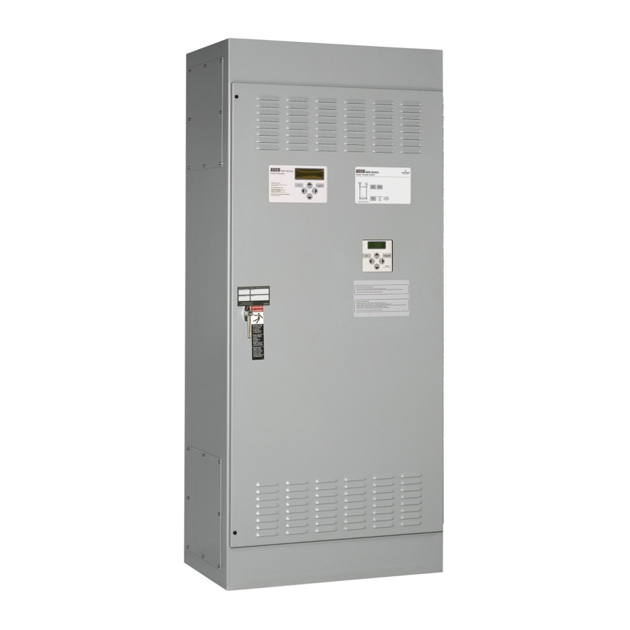
User's Guide
cut–out opening
in enclosure
door
Menu Scroll
Esc
(left/right)
key
keys
Power Control Center keypad and display
DANGER is used in this manual to warn of high
voltages capable of causing shock, burns, or death.
WARNING is used in this manual to warn
of possible personal injury.
CAUTION is used in this manual to warn
of possible equipment damage.
Refer to the outline and wiring drawings provided with
the 4000 or 7000 Series ATS product for all installation
and connection details and accessories.
ASCO POWER TECHNOLOGIES CANADA PO Box 1238, 17 Airport Road, Brantford, Ontario, Canada N3T 5T3
telephone 519 758–8450, fax 519 758–0876, for service call 1 888 234–2726 (ASCO)
for
Automatic Transfer Switch Products
4–line
LCD
display
Enter/Save
Settings
key
Increase (up)/
Decrease (down)
Value keys
50 Hanover Road, Florham Park, New Jersey 07932–1591 USA
For sales or service call 1 800 800–2726 (ASCO)
Group 5 Controller
4000 & 7000 Series
Refer to the Operator's Manual for the ASCO 4000 or
7000 Series ATS product for installation, functional
testing, sequence of operation,and troubleshooting.
ASCO 4000 & 7000 Series Automatic Transfer Switch
products utilize the Group 5 Controller for sensing,
timing, and control functions. This state–of–the art
microprocessor–based controller includes a built–in
keypad and a four–line LCD display. All monitoring and
control functions can be done with the enclosure door
closed for greater convenience. In addition, all changes
in voltage settings (except for nominal voltage) and time
delays can be made through a system of menus.
TABLE OF CONTENTS
OVERVIEW
Controls
. . . . . . . . . . . . . . . . . . . . . . . . . . . . . .
Settings
. . . . . . . . . . . . . . . . . . . . . . . . . . . . . .
SETTINGS
How to Change a Setting
Voltage & Frequency
Time Delays
Features
. . . . . . . . . . . . . . . . . . . . . . . . . . . . . .
General
. . . . . . . . . . . . . . . . . . . . . . . . . . . . . .
Engine Exerciser
View Event Log
Service — Statistics / Diagnostics
OPERATING the CONTROLS
Status of ATS and Sources
Display Messages and Their Meanings
DESCRIPTION of OPERATION
Open–Transition
Closed–Transition
Delayed–Transition
APPENDIX
DIP switch actuators
Voltage jumper blocks
INDEX
. . . . . . . . . . . . . . . . . . . . . . . . . .
www.ascopower.com
www.asco.ca
Description
section-page
. . . . . . . . . . . . . . .
. . . . . . . . . . . . . . . . . . .
. . . . . . . . . . . . . . . . . . . . . . . . . .
. . . . . . . . . . . . . . . . . . . . .
. . . . . . . . . . . . . . . . . . . . . . .
. . . . . .
. . . . . . . . . . . . .
. . . . . . . . . . . . . . . . . . . . . . .
. . . . . . . . . . . . . . . . . . . . . .
. . . . . . . . . . . . . . . . . . . .
. . . . . . . . . . . . . . . . . . .
. . . . . . . . . . . . . . . . .
back page
381333–126 K
1-1
1-2
2-1
2-2
2-4
2-6
2-8
2-10
2-12
2-13
3-1
. . .
3-2
4-1
4-3
4-6
A-2
A-4
Advertisement

Related Manuals for Asco 4000 Series


Summary of Contents for Asco 4000 Series
- Page 1 50 Hanover Road, Florham Park, New Jersey 07932–1591 USA For sales or service call 1 800 800–2726 (ASCO) www.ascopower.com ASCO POWER TECHNOLOGIES CANADA PO Box 1238, 17 Airport Road, Brantford, Ontario, Canada N3T 5T3 telephone 519 758–8450, fax 519 758–0876, for service call 1 888 234–2726 (ASCO) www.asco.ca...
- Page 2 1--1 Overview Control Overview On the Power Control Center, six keys allow access to all monitoring and setting functions. Two levels of screens are used. The status level provides information about the automatic transfer switch. The settings level allows configuration of the controller.
- Page 3 Overview 1--2 Settings Overview The controller settings can be displayed and changed from the keypad. Some settings may require a password (if the controller is set up for one). From the ATS Status display, press Enter/Save Settings ¿ key to move to the Settings level of menus.
- Page 4 2--1 Settings How to Change a Setting To change a setting in the controller (CP): ¡ ¡ Navigate to the settings screen that you want to change (see page 1–2). © Press Enter/Save Settings ¿ key to start the first field blinking. If the controller ©...
- Page 5 Settings 2---2 Voltage & Frequency Settings Unless otherwise specified on the order, the controller voltage and frequency settings are set at the factory to the default values. If a setting must be changed, carefully follow the procedure on the next page. Some settings may require a password (if the controller is set up for one).
- Page 6 2--3 Settings Voltage & Frequency Settings The controller (CP) voltage and frequency setting can be displayed and changed from the keypad. See the table on the previous page. Some settings may require a password (if the controller is set up for one). ¡...
- Page 7 Settings 2---4 Time Delay Settings Unless otherwise specified on the order, the Controller time delay settings are set at the factory to the default values. If a setting must be changed, follow the procedure on the next page. Some settings may require a password (if controller is set up for one). Any indiscriminate change in these settings may affect the normal operation of the Automatic Trans- fer Switch.
- Page 8 2---5 Settings Time Delay Settings The controller time delay (TD) settings can be displayed and changed from the keypad. Some settings may require a password (if the control panel is set up for one). From any of the Status displays, press the Enter/Save Settings key to move to the Settings level of menus.
- Page 9 Settings 2---6 Features Settings Unless otherwise specified on the order, the controller features settings are set at the factory to the default values. If a setting must be changed, follow the procedure on the next page. Some settings may require a password (if the controller is set up for one). Any indiscriminate change in these settings may affect the normal operation of the Automatic Trans- fer Switch.
- Page 10 2--7 Settings Features Settings The controller (CP) Features settings can be displayed and changed from the key- pad. Some settings may require a password (if the controller is set up for one). ¡ From any of the Status displays, press the Enter/Save Settings ¿ key to move to the Settings level of menus.
- Page 11 Clear Log door–mounted user controls locked but not the Power Control Center yes or no Keypad Locked (this setting on 4000 Series only) 4 characters Change password 1111 letters or numbers Password * Note: If the language setting ENGLISH S1–S2 is selected the usual display words...
- Page 12 2–1 This display shows the status of the optional printer. Also see Printer Interface Module instructions 381339---218. Change User Controls Locked (on 4000 Series only) Password: 0001 see page 2–1 This display allows the user to lock or unlock the door–mounted user controls.
- Page 13 Settings 2---10 Engine Exerciser Settings Unless otherwise specified on the order, the controller engine exerciser settings are set at the factory to the default values. If a setting must be changed, follow the procedure on the next page. Some settings may require a password (if the controller is set up for one).
- Page 14 2---11 Settings Engine Exerciser Settings The controller (CP) engine exerciser setting can be displayed and changed from the keypad. Some settings may require a password (if the controller is set up for one). From any of the Status displays, press Enter/Save Settings key to move to the Settings level of menus.
- Page 15 Settings 2--12 View Event Log The controller event logging feature can be displayed from the keypad. Some settings may require a password (if the controller is set up for one). ¡ From any of the Status displays, press Enter/Save Settings key to move to the Settings level of menus.
- Page 16 2--13 Settings Service — Statistics / Diagnostics The controller service statistics / diagnostics can be displayed from the keypad. Some settings may require a password (if the controller is set up for one). ¡ From any of the Status displays, press Enter/Save Settings key to move to the Settings level of menus.
- Page 17 Settings 2--14 Service — Factory Selectable Features The controller service factory selectable features can be displayed from the membrane controls. These factory settings should not be changed by the customer NORMAL OK (they cannot be changed without entering the factory password). ¡...
- Page 18 3--1 Operating the Controls Status Information The controller (CP) provides the status of the automatic transfer switch (ATS) and of both the normal and emergency sources. This information is at the status level of all screens and no password is required to view them. You can press the right arrow "...
- Page 19 Operating the Controls 3--2 Display Messages and their Meaning The following messages (in alphabetical order) can appear on the CP display: Display Message Meaning or Explanation Also Refer To An error condition has occurred and the controller Transfer has locked out all further attempts to transfer the Switch ATS LOCKED OUT! load.
- Page 20 3--3 Operating the Controls Display Messages and their Meaning (continued) The following messages (in alphabetical order) can appear on the CP display: Display Message Meaning or Explanation Also Refer To The normal source failure time delay (Feature 1C) TD Normal Fail: is running.
- Page 21 Description of Operation 4--1 Open–Transition (2–position) Automatic Transfer (4ATS,7ATS,7ATB) Load Transfer To Emergency The sequence for load transfer to the emergency source begins automatically when the NORMAL FAILED controller detects a normal source failure or a transfer test signal. Normal Source Failure. The Normal source is considered unacceptable when any one of six voltage, frequency, or phase rotation conditions occur (see page 3–1).
- Page 22 4--2 Description of Operation Open–Transition (2–position) Automatic Transfer Switches continued Load Retransfer To Normal The sequence for load retransfer to the normal source begins automatically when the NORMAL OK controller detects a restored normal source or a cancelled transfer test signal. Load on Emerg Normal Source Restoration.
- Page 23 Description of Operation 4--3 Closed–Transition Automatic Transfer (4ACTS, 7ACTS, 7ACTB) The 4ACTS, 7ACTS, and 7ACTB provides load transfer in either closed (make–befo- re–break) or open (break–before–make) transition modes depending upon the condition of the two power sources. Control logic automatically determines whether the load trans- fer should be open or closed transition.
- Page 24 4--4 Description of Operation Closed–Transition Automatic Transfer Switches continued Closed–Transition Load Transfer to Emergency Source due to Transfer Test The sequence for closed–transition load transfer to the emergency source begins automatically when the controller detects a transfer test signal. Transfer Test Signal. Test transfer signal can be from the Transfer Control switch (Feature 5), the engine–generator exerciser clock (Feature 11C), or via the serial port TEST MODE (Feature 72A).
- Page 25 Description of Operation 4--5 Closed–Transition Automatic Transfer Switches continued Closed–Transition Load Retransfer To Normal The sequence for load retransfer to the normal source begins automatically when the controller detects a restored normal source or a cancelled transfer test signal. Normal Source Restoration. The Normal source is considered acceptable again when NORMAL OK all six voltage, frequency, or phase rotation conditions occur (see page 3–1).
- Page 26 4--6 Description of Operation Delayed–Transition Automatic Transfer (4ADTS, 7ADTS, 7ADTB) Load Transfer To Emergency The sequence for load transfer to the emergency source begins automatically when the NORMAL FAILED controller detects a normal source failure or a transfer test signal. Normal Source Failure.
- Page 27 Description of Operation 4--7 Delayed–Transition Automatic Transfer Switches continued Load Retransfer To Normal The sequence for load retransfer to the normal source begins automatically when the NORMAL OK controller detects a restored normal source or a cancelled transfer test signal. Load on Emerg Normal Source Restoration.
- Page 28 (open, closed, delayed transition). These Deenergize all power before removing cover. controls should only be used by trained technicians from ASCO Services, Inc. (ASI 1–800–800–2726). NOTICE ATTENTION DIP switch actuators see page A–2...
- Page 29 Appendix A---2 DIP Switch Actuators The DIP switch in the Group 5 controller is located on the right side through a opening in the base. The following tables show what each actuator does. Transfer Switch Type DIP switch actuators 1 and 2 select the type of transfer switch used with the controller (open–transition, closed–transition, or delayed–transition).
- Page 30 A---3 Appendix Frequency of Sources Data Input Lock DIP switch actuator 7 selects either 50 or 60 Hz source The Group 5 controller has an external input for a dry frequency. See Table C. contact that, if closed, prevents setting changes from the keypad.
- Page 31 Appendix A---4 Voltage Jumper Blocks Eight jumper blocks on the Group 5 controller are arranged in one of two patterns for the power supply to meet the requirements of the 16 different voltage inputs (shown in Table B on page A–2). These jumpers are located on the front right side near the ribbon To avoid permanently damaging the Group 5 controller, be certain that the voltage setting...
- Page 32 Esc (escape) push–button, 1–1 event logging, 2–8, 2–9, 2–12 open–transition transfer, 4–1 Y–Y primary failure detect, 2–6, 2–8 In the United States, for service call ASI at 1–800–800–2726 (ASCO). Copyright Printed in U.S.A. ASCO Power Technologies, L.P . 2007 In Canada, for service call at 1–888–234–2726 (ASCO).
Need help?
Do you have a question about the 4000 Series and is the answer not in the manual?
Questions and answers