Asco 7000 Series Operator's Manual
Hide thumbs
Also See for 7000 Series:
- User manual (17 pages) ,
- Installation manual (16 pages) ,
- Operator's manual (12 pages)
Table of Contents
Advertisement
Quick Links
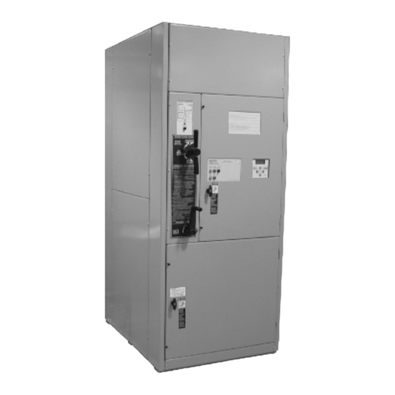
ASCO 7000 SERIES ACTB
Automatic Closed-Transition Transfer &
Bypass-Isolation Switches
H design 600 through 1200 A
Operator's Manual
381333-194 B
9/2016
DANGER is used in this manual to warn of a
hazard situation which, if not avoided, will result
in death or serious injury.
WARNING is used in this manual to warn of a
hazardous situation which, if not avoided, could
result in death or serious injury.
CAUTION is used in this manual to warn of a
hazardous situation which, if not avoided, could
result in minor or moderate injury.
Refer to the outline and wiring drawings provided with
your 7000 Series ACTB for all installation and
connection details and accessories
Refer to Group 5 Controller User's Guide 381333–126
for ATS status display messages, time delays, pickup &
dropout settings, and adjustments.
Rating Label
Each 7000 Series 7ACTB contains a rating label to
define the loads and fault circuit withstand/closing
ratings. Refer to the label on the Transfer Switch for
specific values.
Do not exceed the values on the rating label.
Exceeding the rating can cause personal injury
or serious equipment damage.
.
An experienced licensed electrician must install the
7ACTB.
600-1200 amp sizes
Advertisement
Table of Contents

Related Manuals for Asco 7000 Series


Summary of Contents for Asco 7000 Series
-
Page 1: Rating Label
ATS status display messages, time delays, pickup & dropout settings, and adjustments. Rating Label Each 7000 Series 7ACTB contains a rating label to define the loads and fault circuit withstand/closing ratings. Refer to the label on the Transfer Switch for specific values. - Page 2 Operator’s Manual 7000 Series ACTB This page left blank intentionally. 381333-194 B...
-
Page 3: Table Of Contents
7000 Series ACTB Operator’s Manual Table of Contents Rating Label ................................1 Nameplate ................................4 Catalog Number Identification ..........................4 Installation .................................. Remove the Skid ..............................5 Supporting Foundation ............................. 5 Mounting ................................... 5 Line Connections ..............................5 Testing Power Conductors ............................5 Connecting Power Conductors .......................... -
Page 4: Nameplate
The Transfer Switch nameplate includes data for each Typical 7000 Series ACTB catalog no. for switched specific 7000 Series ACTB. Use the switch only within neutral, 3 pole, 600 amp, 480 V, in Type 1 enclosure: the limits shown on this nameplate. A typical catalog... -
Page 5: Installation
Installation Operator’s Manual Installation ASCO 7000 Series Automatic Transfer & Bypass– Testing Power Conductors Isolation Switches (7ACTBs) are factory wired and Do not connect the power conductors to the transfer tested. Field installation requires mounting switch until they are tested. Installing power cables in... -
Page 6: Engine Starting Contacts
Operator’s Manual Installation Installation Engine Starting Contacts All customer connections, including the engine control contact connections, are located on terminal block TB which is mounted on the top right side of the enclosure. Refer to the wiring diagram provided with the automatic transfer switch and connect the engine start wires to the appropriate terminals. -
Page 7: Functional Test - Voltage Checks
Installation Operator’s Manual Installation observe these lights Figure 2. Standard controls and indicators. Functional Test Close the normal source circuit breaker. The Transfer Switch Read all instructions on the Wiring Diagrams and labels Connected To Normal and the affixed to the 7ACTB. Note the control features that are Normal Source Accepted lights provided and review their operation before proceeding. -
Page 8: Functional Test - -Electrical Operation
Operator’s Manual Installation Installation observe operate these lights this switch Figure 3. Standard controls and indicators. 2 – Electrical Operation The Transfer Switch Connected To This procedure checks electrical operation of the ACTS. Normal and Normal Source Accepted lights should be on. Close enclosure door before proceeding to prevent Turn and hold Transfer Control personal injury in case of electrical system fault. -
Page 9: Testing & Service
Emergency source, then back to the In the United States and Canada Normal source. With both sources available the load will call 1 – 800 – 800 – ASCO ( 2726 ) be transferred in a closed–transition mode. DISCONNECTING THE CONTROLLER The harness disconnect plugs are furnished for repair purposes only and should not have to be unplugged. -
Page 10: Trouble-Shooting
These are factory settings. Refer to the Controller User’s Guide. If the problem is isolated to circuits on the controller or the transfer switch, call your local ASCO Power Technologies sales office or ASCO Power Services, Inc.: in the United States or Canada, call 1–800–800–2726. Furnish the Serial No., Catalog No., and Bill of Material (BOM) No. -
Page 11: Maintenance Handle
Testing & Service Operator’s Manual MAINTENANCE HANDLE Table C. Maintenance handle positions ATS Position Handle Indicators Bypass and isolate the Transfer Switch before using the maintenance handle! See pages 12-15. Remove the maintenance handle after using it; E = O store it inside. -
Page 12: Bypassing & Isolating
Operator’s Manual Bypassing & Isolating Bypassing & Isolating BYPASSING THE ATS* This procedure explains how to Bypass the closed transfer switch contacts. Bypassing is required before the Transfer Switch can be tested or isolated. The Bypass Switch Handle must be in the OPEN position (green window indicator) and the Isolation Handle must be in the CONN [connected] position (window indicator). -
Page 13: To Bypass Normal Source
Bypassing & Isolating Operator’s Manual Bypassing & Isolating To Bypass Normal Source* To Bypass Emergency Source* (Load connected to Normal Source) (Load connected to Emergency Source) The Transfer Switch Connected To Normal light is on The Transfer Switch Connected To Emergency light is and Transfer Switch Connected To Emergency light is on and Transfer Switch Connected To Normal light is off. -
Page 14: Isolating The Ats
Operator’s Manual Bypassing & Isolating Bypassing & Isolating ISOLATING THE ATS NOTE: In the TEST position the transfer switch solenoid operator circuit is energized through Isolating is required before any service work can be secondary disconnects. performed on the automatic transfer switch (ATS). Refer to Figures 15, 16, 17 and 18. -
Page 15: Contact Inspection
Bypassing & Isolating Operator’s Manual Bypassing & Isolating 4. Open the lower enclosure door. Pull out both left and right side rails then use the two tab handles to To prevent the possibility of fatal electrical shocks roll out the transfer switch. It can be safely inspected in this position. -
Page 16: Return To Service
Operator’s Manual Bypassing & Isolating Bypassing & Isolating RETURN TO SERVICE 5. Remove the movable contact cover. Use your thumb and fingers to squeeze the sides This procedure explains how to return the automatic inward until the contact cover is released from the transfer switch (ATS) to service after inspection and shaft clamp (both sides). - Page 17 Bypassing & Isolating Operator’s Manual Bypassing & Isolating Middle amber light Do not close the isolation contacts unless should come on. the Transfer Switch (ATS) and Bypass Switch are in the same position! 6. When the transfer switch is in the same position as the Bypass Switch handle, continue turning the Isolation Handle clockwise (about 8 turns) until the window shows CONN (connected).
-
Page 18: To Un-Bypass Normal Source
Operator’s Manual Bypassing & Isolating Bypassing & Isolating RETURN TO SERVICE continued* Window indicator This procedure explains how to return the Bypass Switch shows yellow Handle to the OPEN position. The Bypass Handle must when ATS is be in the CLOSED position (yellow indicator on NORMAL bypassed to or EMERGENCY) and the Isolation Handle must be in Emergency. -
Page 19: Index
15. 16 isolating the ATS, 14, 15 bypassing the ATS, 12, 13 service lifting device, transfer switch, 15 ASCO Power Services, Inc., 9 catalog number, 4 lights, 6, 7, 12, 13, 14 settings cleaning, 9 load connected to emergency, 7 see Controller User’s Guide... - Page 20 Printed in U.S.A. ASCO Power Technologies 160 Park Avenue Florham Park, NJ 07932-1591 USA Phone: 1 800 800-2726 (ASCO) for sales or service www.ascopower.com ©2016 ASCO Power Technologies. All Rights Reserved...
Need help?
Do you have a question about the 7000 Series and is the answer not in the manual?
Questions and answers