Asco 7000 Series Installation Manual

Asco 7000 Series Installation Manual

Automatic transfer & bypass–isolation switches g, q, s, & u design
Hide thumbs Also See for 7000 Series:

Advertisement

Quick Links

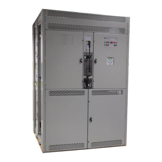
ASCO 7000 SERIES 7ATB, 7ACTB, 7ADTB
Automatic Transfer & Bypass–Isolation Switches
G, Q, S, & U design
Installation Manual
381333-415 A
9/2016
DANGER is used in this manual to warn of a
hazardous situation which, if not avoided, will
result in death or serious injury.
WARNING is used in this manual to warn of a
hazardous situation which, if not avoided, could
result in death or serious injury.
CAUTION is used in this manual to warn of a
hazardous situation which, if not avoided, could
result in minor or moderate injury.
Refer to the outline and wiring drawings provided with
your 7000 Series ATB for all installation and
connection details and accessories.
Refer to Group 5 Controller User's Guide 381333–126
for ATS status display messages, time delays, pickup
& dropout settings, and adjustments.

Rating Label

Each 7000 Series ATB contains a rating label to
define the load and fault circuit withstand/closing
ratings. Refer to the label on the Transfer Switch for
specific values.
Do not exceed the values on the rating label.
Exceeding the rating can cause personal injury
or serious equipment damage.
An experienced licensed electrician must install
the ATB.

Nameplate

The Transfer Switch nameplate includes data for each
specific 7000 Series ATB Use the switch only within
the limits shown on this nameplate. A typical Catalog
Number is shown below with its elements explained:
typical 4000 A

Advertisement

Table of Contents
loading
Need help?

Need help?

Do you have a question about the 7000 Series and is the answer not in the manual?

Questions and answers

Summary of Contents for Asco 7000 Series

  • Page 1: Rating Label

    The Transfer Switch nameplate includes data for each result in death or serious injury. specific 7000 Series ATB Use the switch only within the limits shown on this nameplate. A typical Catalog Number is shown below with its elements explained:...
  • Page 2: Table Of Contents

    Installation Manual 7000 Series ATB, ACTB, ADTB Table of Contents Rating Label................................1 Nameplate ................................1 Catalog Number Identification ..........................3 Installation ................................Remove the Shipping Skid ............................4 Supporting Foundation and Mounting ........................4 Mounting ................................... 4 Remove Shipping Brackets/Angles from the Transfer Switch .................. 4 Testing Power Conductors ............................
  • Page 3: Catalog Number Identification

    7000 Series ATB, ACTB, ADTB Installation Manual Catalog Number Identification Typical 7000 Series G7ATB catalog no. for overlapping neutral, 3 pole, 4000 A, 480 V, in a Type 1 enclosure: 4000 Design Transition Neutral Phase Amperes Voltage Controller Enclosure Type...
  • Page 4: Installation

    Allow at least 35 inches in front of the enclosure for draw out of the Transfer Switch. Refer to the enclosure outline drawing included with the 7000 Series ATB for all mounting details including door opening space. If bottom cable entry is used, the foundation must be prepared so that the conduit stubs are located correctly.
  • Page 5: Testing Power Conductors

    Installation Installation Manual Bus Connections If bus connection is used, use SAE grade 5 hardware De–energize the conductors before making any to connect bus to appropriate terminal plates on line or auxiliary circuitry connections. Be sure bypass switching device. Wipe off bus surfaces that Normal and Emergency line connections are before they are joined.
  • Page 6: Functional Test

    Installation Manual Installation 1 Close the normal source circuit breaker. The Transfer Switch Connected To Normal and the Normal Source Accepted lights should come on. 2 Use an accurate voltmeter to check phase to phase and phase observe to neutral voltages present at the these transfer switch normal source lights...
  • Page 7 Installation Installation Manual 7ACTB alarm lights (see troubleshooting) 7ACTB buttons 7ADTB light is on when load is disconnected observe these lights Figure 5. 7ACTB controls. Figure 6. operate 7ADTB controls this switch 1 The Transfer Switch Connected to Normal and Normal Source Accepted lights should be on.
  • Page 8: Testing & Service

    Bypass Switch. Then Bypass to the other PREVENTIVE MAINTENANCE source (see page 10). Reasonable care in preventive maintenance will insure high reliability and long life for the 7000 Series MAINTENANCE HANDLE ATB. An annual preventive maintenance program is recommended.
  • Page 9: Troubleshooting

    * These are factory settings. Refer to Controller User’s Guide. If the problem is isolated to circuits on the controller or the transfer switch, call your local ASCO Power Technologies sales office or ASCO Power Services, Inc at 1–800–800–2726. Furnish the Serial No. and Catalog No.
  • Page 10: Bypassing & Isolating

    Installation Manual Bypassing & Isolating BYPASSING & ISOLATING BYPASSING THE ATS* You can only bypass to the same source that the This procedure explains how to Bypass the closed Transfer Switch is connected. Solenoid interlock automatic transfer switch contacts. Bypassing is prevents incorrect operation. required before the ATS can be tested or isolated.
  • Page 11: Isolating The Ats

    Bypassing & Isolating Installation Manual position. The transfer switch can also be ISOLATING THE ATS removed for easier maintenance operations. Isolating is required before any service work can be performed on the automatic transfer switch (ATS). position Refer to Figures 11,12, 13, 14 and 15.. CONN window TEST...
  • Page 12 Installation Manual Bypassing & Isolating grasp two handles locking pin with clevis pin rail support carriage left support leg locking pin with clevis pin adjust length to touch floor right support leg 4000 A transfer switch draw – out procedure adjust length to touch floor 1.
  • Page 13: Return To Service

    Bypassing & Isolating Installation Manual RETURN TO SERVICE This procedure explains how to return the automatic Solenoid interlock prevents closing the isolation transfer switch (ATS) to service after inspection and maintenance. Observe the Bypass Switch Position contacts until the ATS is in the same position as indicator and lights).
  • Page 14 Installation Manual Bypassing & Isolating RETURN TO SERVICE continued* This procedure explains how to return the Bypass You can only bypass to the same source that the Switch Handle to the OPEN position. The Bypass ATS is connected. Solenoid interlock prevents Handle must be in the CLOSED position (yellow incorrect operation.
  • Page 15: Index

    5 return to service, 13 inspection, 10 installation, 4 through 7 bus connections, 5 service isolating the ATS, 11 ASCO Power Services, Inc., 8 bypassing the ATS, 10 customercare@asco.com 800–800–2726(ASCO) settings lights, 1–3, 1–4 catalog number, 3 see Controller User’s Guide Load Disconnect Active light, 381333–126...
  • Page 16 Printed in U.S.A. ASCO Power Technologies 160 Park Avenue Florham Park, NJ 07932-1591 USA Phone: 1 800 800-2726 (ASCO) for sales or service www.ascopower.com ©2016 ASCO Power Technologies. All Rights Reserved...

This manual is also suitable for:

7atb7actb7adtb

Table of Contents