Advertisement
Quick Links
Operator's
Manual
DANGER is used in this manual to warn
of high voltages capable of causing shock,
burns, or death.
!
WARNING is used in this manual to warn
of possible personal injury.
!
CAUTION is used in this manual to warn
of possible equipment damage.
ASCO POWER TECHNOLOGIES L.P .
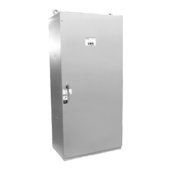
Non-Automatic Transfer Switches
600-1000 amp sizes
50 Hanover Road, Florham Park, New Jersey 07932 USA
386
Electrically-Operated
600 through 1200 amps
Note:
Refer to the outline and wiring drawings
provided with your ASCO 386 Non-Automatic
Transfer Switch for all installation and connection
details and accessories.
An experienced licensed electrician must install the Non-
Automatic Transfer Switch.
Rating Label
Each Non-Automatic Transfer Switch contains a rating label
to define the loads and fault circuit withstand/closing ratings.
Refer to the label on the Transfer Switch for specific values.
!
Do not exceed the values on the rating label.
Exceeding the rating can cause personal
injury or serious equipment damage.
Identification Label
The identification label on the Transfer Switch includes
data for each specific ASCO 386. Use the switch only within
the limits shown on identification label.
TABLE OF CONTENTS
. . . . . . . . . . . . . . . . . . . . . . . .
. . . . . . . . . . . . . . . . . . . . . . . .
. . . . . . . . . . . . . . . . . . . . . . .
. . . . . . . . . . . . . . . . . . . . . . .
. . . . . . . . . . . . . . . . . . . . . . . . .
www.asco.com
1-1
1-2
. . . . . . . . . . .
2-1
. . . . . . . . . . . . . . . . . .
3-1
3-2
4-1
. . . . . . . . . . . . . . . . .
5-1
back cover
381333-209
Advertisement

Related Manuals for Asco 386


Summary of Contents for Asco 386
-
Page 1: Table Of Contents
Exceeding the rating can cause personal injury or serious equipment damage. Identification Label The identification label on the Transfer Switch includes data for each specific ASCO 386. Use the switch only within the limits shown on identification label. 600–1000 amp sizes TABLE OF CONTENTS... - Page 2 Catalog Number Indentification Typical ASCO 386 catalog no. for solid neutral, 3 pole, 800 amp, 480 V, N–ATS in Type 1 enclosure: H386 Neutral Phase Poles Amperes Voltage Controller Enclosure – solid – single Ø – standard – type 1 –...
-
Page 3: Installation
ASCO interlocking conduit spacer caps or a wood or metal 386. Make sure the lugs provided are suitable for use with template to maintain proper conduit alignment. the cables being installed. Standard terminal lugs are solderless screw type and will accept the wire sizes listed on the drawings provided with the ASCO 386. -
Page 4: Functional Test
INSTALLATION (continued) Auxiliary Circuits Connect auxiliary circuit wires to appropriate terminals on transfer switch terminal block TB as shown on the wiring diagram provided with this Non–Automatic Transfer Switch. auxiliary contact connections customer terminal block TB Figure 1-1. Customer terminal block on the top right side of the enclosure. - Page 5 INSTALLATION (continued) 1 – Manual Operation Test A detachable maintenance handle is provided on the frame of the Transfer Switch for maintenance purposes only. Manual operation of the transfer switch should be checked before it is energized (operated electrically). Do not manually operate the transfer switch until both power sources are disconnected: left side of open both circuit breakers.
- Page 6 3. Turn the door-mounted Transfer Control switch tor according to the manufacturer’s recommendations. counterclockwise to Transfer To Normal. The ASCO 386 will respond only to the rated voltage specified on the Transfer Switch nameplate. 4. The transfer switch will operate back to the Normal 5.
-
Page 7: Sequence Of Operation
SECTION 2 SEQUENCE OF OPERATION Control Panel Code 1 Refer to Section 5, Optional Accessories for additional control functions. Refer to Wiring Diagram furnished with the ASCO 386. Note Control Features furnished on this switch, and review operation. Transfer Transfer Control... -
Page 8: Testing & Service
Serial No., Bill of Material No. preventive maintenance program is recommended. (BOM), and Catalog No. from the transfer switch nameplate. Contact your local ASCO Power Technolo- gies Sales Office or ASI: ASCO Services, Inc. (ASI) is ASCO Power Technologies’... -
Page 9: Troubleshooting
5. Disconnect the voltmeter. If the problem is isolated to circuits on the controller or the transfer switch, call your local ASCO Power Technologies sales office or ASI at 1–800–800–2726. Furnish the Serial No. and Catalog No. from transfer switch nameplate. -
Page 10: Adjustments
Any change in these settings may affect the are factory set as specified on the Wiring Diagram. The normal operation of the ASCO 386. frequency setting can be set for 50 or 60 Hz.. To change This change could allow the load circuits to this setting, follow the procedure below. -
Page 11: Optional Features
SECTION 5 OPTIONAL FEATURES MOTOR LOAD TRANSFER LOAD DISCONNECT FEATURE Connect external circuits to the terminals indicated on Inphase monitoring logic controls transfer and retransfer the Wiring Diagram in the back of this manual. of motor loads, so that inrush currents do not exceed normal starting currents. -
Page 12: Index
50 or 60 Hz setting, 4–1 transfer to normal, 1–4, 2–1, 3–1 trouble–shooting, 3–2 functional test, 1–2 inphase monitor, 3–2 harness, 1–2 disconnect plugs, 3–1 nameplate, cover voltage checks, 1–4 2001 ASCO Power Technologies L.P . Printed in U.S.A.
Need help?
Do you have a question about the 386 and is the answer not in the manual?
Questions and answers