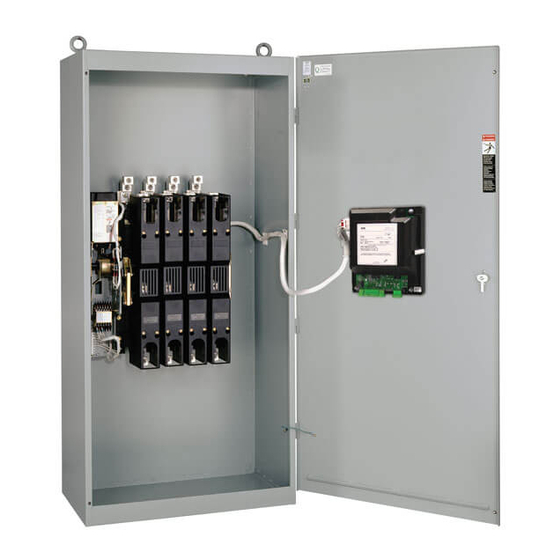
Asco 3ATS Installation Manual

Asco 3ATS Installation Manual

J-design 260-600 a, 150-600 a transfer switches

Advertisement

ASCO
COMMON ALARM & NOT IN AUTO SIGNALING FEATURES
NON-AUTOMATIC (MANUAL) OPERATION
REMOTE CONTROL FEATURES
ENGINE CONTROL CONTACTS
EXTERNAL POWER SUPPLY COMPATIBILITY
LOAD DISCONNECT FEATURE
LOAD CURRENT METERING
INPHASE TRANSFER FEATURE FOR LOAD TRANSFER
FOUR-FUNCTION SOFTWARE BUNDLE
SOURCE AVAILABILITY SIGNALS
ASCO
ASCO

Advertisement

Table of Contents
loading
Need help?

Need help?

Do you have a question about the 3ATS and is the answer not in the manual?

Questions and answers

Subscribe to Our Youtube Channel

Summary of Contents for Asco 3ATS

  • Page 1 ASCO COMMON ALARM & NOT IN AUTO SIGNALING FEATURES NON-AUTOMATIC (MANUAL) OPERATION REMOTE CONTROL FEATURES ENGINE CONTROL CONTACTS EXTERNAL POWER SUPPLY COMPATIBILITY LOAD DISCONNECT FEATURE LOAD CURRENT METERING INPHASE TRANSFER FEATURE FOR LOAD TRANSFER FOUR-FUNCTION SOFTWARE BUNDLE SOURCE AVAILABILITY SIGNALS...
  • Page 2 ASCO ASCO...
  • Page 3 ASCO...
  • Page 4 ASCO...
  • Page 5 ASCO...
  • Page 6 ASCO...
  • Page 7 ASCO...
  • Page 8: Table Of Contents

    Refer to the applicable enclosure outline drawing Refer to the outline and wiring drawings provided included with the transfer switch for all mounting details with the 3ATS, 3NTS, 3ADTS, or 3NDTS for all including door opening space. installation and connection details and accessories.
  • Page 9: Power Connections

    The engine control contact connections are located on the Refer to the wiring diagram provided with the transfer switch. transfer switch for 3ATS & 3NTS or upper right of the All wiring must be made in accordance with the National enclosure for 3ADTS &...
  • Page 10: Functional Test

    See Figures 3, 4, 5, & 6. See Figure 2 for the contact position indicators. Figure 4. Maintenance handle on 3ATS & 3NTS 2. Install the handle into the hole in the molded hub. Move the handle up or down as shown to manually operate the transfer switch.
  • Page 11 ASCO 3ATS, 3ADTS, 3NTS, 3NDTS Installation Manual UPPER SHAFT LOWER SHAFT Emergency contacts handle Normal source contacts Table B. 3ADTS & UP opens 3NDTS The contacts UP closes the contacts DOWN closes The contacts frame DOWN opens the contacts Figure 6. Maintenance handle operation on 3ADTS & 3NDTS Table B.
  • Page 12: 2- Voltage Checks

    Installation Manual ASCO 3ATS, 3ADTS, 3NTS, 3NDTS Close the normal source circuit breaker. The normal source accepted and the load on normal lights should come on. Use an accurate voltmeter to check phase to phase and phase to neutral voltages present at the transfer switch normal source terminals.
  • Page 13: 3- Electrical Operation

    15 seconds. For 3NTS & 3NDTS the generator must be started manually at the generator. The emergency source accepted light should come on. For 3ATS & 3ADTS the transfer switch should transfer to Observe Press this these the emergency position. The load on emergency light...
  • Page 14: Testing & Service

    Transfer Test of Material No. (BOM), and Catalog No. from the transfer Operate the transfer switch at least once a month by following switch nameplate. In the US call 800-800-2726 (ASCO) or the Electrical Operation procedure on page 6. contact customercare@asco.com.
  • Page 15: Troubleshooting

    1 Operation 2 Generator 3 Voltage Starting control must be The outage must be long For 3ATS & 3ADTS the engine- in automatic position. enough to allow for the generator set does not start when Batteries must be feature 1C time delay plus the transfer test button is pressed charged and connected.

This manual is also suitable for:

3nts3adts3ndts

Table of Contents