Advertisement
Available languages
Available languages
INSTALLATION INSTRUCTIONS FOR DETECTOR ISOLATOR BASE MODEL B524IEFT-1
GENERAL DESCRIPTION
Before installing detectors, please thoroughly read the system wiring and installation manuals and review the appropriate national and local
standards and codes of practice for the planning and installation of fire alarm systems.
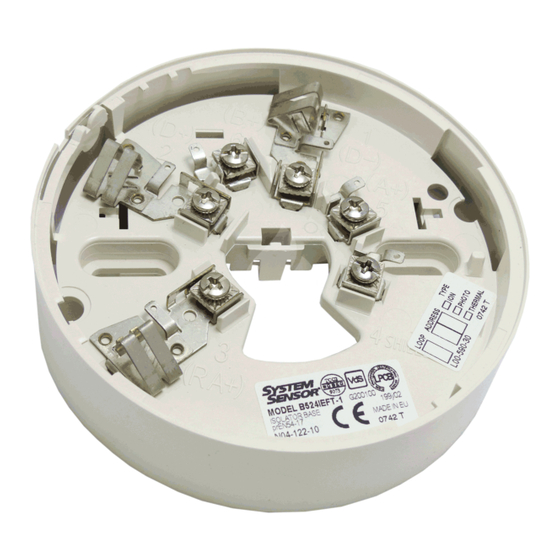
The System Sensor B524IEFT-1 base is designed for use with all 200, 500 and 700 series of analogue addressable detectors. They prevent an
entire communications loop from being disabled when a short circuit occurs. They accomplish this by isolating that part of the loop containing the
short from the remainder of the circuit. These bases also automatically restore the entire loop when the cause of the short circuit is corrected.
The base has been designed such that if the short circuit occurs between adjacent B524IEFT-1 bases and no other products are connected
between, the operation of the entire loop will remain intact in the event of this one short
circuit.
SPECIFICATIONS
Base Diameter
102 mm
Base Height
26 mm
Operating Temperature Range
-30°C to 70°C
Operating Humidity Range
0% to 95% Relative Humidity (Non-
condensing)
Operating Voltage
15 to 28.5 VDC
Standby Current
< 100 µA @ 24 VDC
8µA at 6VDC
Line impedance per base
< 0.2 ohms @ 24 VDC
TAMPER RESIST FEATURE
Note:
Do not use the tamper-resist feature if the removal tool is to be used.
This detector base includes a tamper-resist feature that prevents its removal from the base
without the use of a tool. To activate this feature, break the tab from the detector base as
shown in Figure 2. Then, install the detector. To remove the detector from the base once
the tamper-resist feature has been activated, insert a small-bladed screwdriver into the slot
in the side of the base and push the plastic lever away from the detector head (see Figure 2). This allows the detector to be rotated counter
clockwise for removal.
The tamper-resist feature can be defeated by breaking and removing the plastic lever from the base. However, this prevents the feature from
being used again.
Figure 2: Tamper Resist Feature
BREAK TAB AT DOTTED LINE
PLASTIC LEVER
BY TWISTING TOWARD
CENTRE OF BASE
MOUNTING
The B524IEFT-1 Isolator Base is equipped with mounting holes for fixing to installation boxes with either 2" or 60mm hole spacing. Attach the base
to a suitable junction box, using the screws supplied with the box.
For surface mounting, cut and remove the thin walled sections visible from the back of the base on the outer diameter.
D550-27-10
0832
0832-CPD-0925
Figure 1: Terminal Layout
USE SMALL BLADED SCREWDRIVER TO
PUSH PLASTIC IN DIRECTION OF ARROW.
INSTALLATION GUIDELINES
All wiring must be installed in compliance with all applicable local codes and any special requirements of the local authority having jurisdiction,
using the proper wire sizes. The conductors used to connect smoke detectors to control panels and accessory devices should be colour coded to
reduce the likelihood of wiring errors. Improper connections can prevent a system from responding properly in the event of a fire.
For signal wiring (the wiring between interconnected detectors), it is recommended that the wire be no smaller than 0.5 mm². However, wire
sizes up to 2.5 mm² can be used with the base. The use of twisted pair wiring or shielded cable for the power (+ and -) loop is recommended to
minimize the effects of electrical interference.
If shielded cable is used, the shield connection to and from the detector must be continuous by using wire nuts, crimping, or soldering, as
appropriate, for a reliable connection.
Alarm system control panels have specifications for allowable loop resistance. Consult the control panel specifications for the total loop
resistance allowed before wiring the detector loops.
1.
Make wiring connections by stripping about 10 mm of insulation from the end of the wire. Then, insert the wire into the terminal and tighten
the screw to secure the wire in place.
2.
Check the zone wiring of all bases in the system before installing detectors in them. This includes checking the wiring for continuity, correct
polarity and ground fault testing.
3.
Record the zone, address, and type of detector being installed at the base location on the label affixed to the bottom of the base. This
information is useful for setting the detector head address and for verification of the sensor type required for that location.
4.
Once all detector bases have been wired and mounted, and the loop wiring has been checked, the detector heads may be installed in the
bases.
Figure 3. Typical Wiring
Diagram
COMPATIBLE
CONTROL
PANEL
LIMITATIONS OF SMOKE DETECTORS
This smoke detector is designed to activate and initiate emergency action but will do so only when used in conjunction with other equipment.
Smoke detectors will not work without power.
Smoke detectors will not sense fires which start where smoke does not reach the detectors. Smoke from fires in chimneys, in walls, on roofs, or
on the other side of closed doors may not reach the smoke detector and trigger the unit.
A detector may not detect a fire developing on another level of a building. For this reason, detectors should be located on every level of a building.
Smoke detectors also have sensing limitations. Ionisation detectors offer broad range fire-sensing capability but they are better at detecting fast,
flaming fires than slow, smouldering fires. Photoelectronic detectors sense smouldering fires better than flaming fires. Because fires develop in
different ways and are often unpredictable in their growth, neither type of detector is always best and a given detector may not always provide
warning of a fire. In general, detectors cannot be expected to provide warnings for fires resulting from inadequate fire protection practices, violent
explosions, escaping gas, improper storage of flammable liquids like cleaning solvents, other safety hazards, or arson. Smoke detectors used in
high air velocity conditions may fail to alarm due to dilution of smoke densities created by such frequent and rapid air exchanges. Additionally,
high air velocity environments may create increased dust contamination, demanding more frequent maintenance.
Smoke detectors cannot last forever. Smoke detectors contain electronic parts. Even though detectors are made to last over 10 years, any of
these parts could fail at any time. Therefore, test your smoke detector system at least semi-annually. Clean and take care of your smoke
detectors regularly. Taking care of the fire detection system you have installed will measurably reduce your liability risks.
1
Pittway Tecnologica S.r.l., Via Caboto 19/3, 34147 Trieste, Italy
(-)
TERMINAL
NOTE: DO NOT
1
CONNECT TO D+ (2)
B524IEFT-1-
2
1
4
SENSOR
3
SCREEN
6
5
(+)
WARNING
© System Sensor 2008 I56-0881-012
(-)
TO NEXT DEVICES
RA+
(+)
Advertisement
Table of Contents

Subscribe to Our Youtube Channel
Related Manuals for System Sensor B524IEFT-1


Summary of Contents for System Sensor B524IEFT-1
- Page 1 Additionally, The B524IEFT-1 Isolator Base is equipped with mounting holes for fixing to installation boxes with either 2" or 60mm hole spacing. Attach the base high air velocity environments may create increased dust contamination, demanding more frequent maintenance.
- Page 2 In generale, i rivelatori non sono in grado di offrire protezione da incendi derivanti da procedure antincendio inadeguate, La base isolante B524IEFT-1 è adatta al montaggio su scatole di derivazione con spaziatura dei fori pari a 50.8mm (2") e 60mm. Fissare la base esplosioni improvvise, fughe di gas, depositi impropri di liquidi infiammabili, come i solventi chimici, mancato rispetto delle norme di sicurezza o incendi dolosi.
- Page 3 Los detectores de humo La base aisladora B524IEFT-1 dispone de unos agujeros de montaje para que se pueda instalar en cajas con agujeros de 60mm. Instale la utilizados en condiciones ambientales donde la velocidad del viento es muy elevada podrán no disparar alarmas debido a la dilución de las...
- Page 4 Bevor Sie Melder und Sockel montieren, lesen Sie sich bitte sorgfältig die Installationsanleitung durch. Der Isolator-Sockel B524IEFT-1 wurde entwickelt für die analogen, adressierbaren intelligenten Melder der Serie 200, 500 und 700. Der Sockel ermöglicht die weitere Kommunikation auf dem Ringbus bei einem auftretenden Kurzschluß. Dies geschieht durch Abtrennen des Ringsegments, in dem der Kurzschluß...
Need help?
Do you have a question about the B524IEFT-1 and is the answer not in the manual?
Questions and answers