
Related Manuals for Raymarine RMK-10


Summary of Contents for Raymarine RMK-10
- Page 1 RMK-10 INSTALLATION INSTRUCTIONS English (en-US) Date: 11-2016 Document number: 81367-1 © 2016 Raymarine UK Limited...
- Page 2 Trademark and patents notice Raymarine, Tacktick, Clear Pulse, Truzoom, HSB, SeaTalk, SeaTalk , SeaTalk , Micronet, Raytech, Gear Up, Marine Shield, Seahawk, Autohelm, Automagic, and Visionality are registered or claimed trademarks of Raymarine Belgium. FLIR, DownVision, SideVision, Dragonfly, Quantum, Instalert, Infrared Everywhere, and The World’s Sixth Sense are registered or claimed trademarks of FLIR Systems, Inc.
-
Page 3: Chapter 1: Important Information
• Raymarine recommends certified Disclaimer installation by a Raymarine approved installer. A certified installation qualifies Raymarine does not warrant that this product is for enhanced product warranty benefits. error-free or that it is compatible with products Contact your Raymarine dealer for... -
Page 4: Declaration Of Conformity
EMC performance throughout the installation Declaration of conformity Raymarine UK Ltd. declares that this product is compliant with the essential requirements of EMC directive 2004/108/EC. Product disposal Dispose of this product in accordance with the WEEE Directive. -
Page 5: Chapter 2: Document And Product Information
2.1 Document information 2.2 Product overview This document contains important information The RMK-10 is a Remote Keypad for Raymarine related to the installation of your Raymarine product. multifunction displays (MFD). The keypad is a class 1 PoE (Power Over Ethernet) device and can be... -
Page 6: Chapter 3: Planning The Installation
Power on and test the system. Schematic diagram A schematic diagram is an essential part of planning any installation. It is also useful for any future 1. RMK-10 keypad additions or maintenance of the system. The 2. Landscape keypad mat diagram should include: •... -
Page 7: Software Updates
3.3 Software updates 3.4 Tools required The software running on the product can be updated. Product installation requires the following tools: • Raymarine periodically releases software updates Item Description Quantity to improve product performance and add new Power drill features. -
Page 8: General Location Requirements
3.5 General location requirements 3.6 Warnings and cautions Important considerations when choosing a suitable Important: Before proceeding, ensure that you location for your product. have read and understood the warnings and cautions provided in the Chapter 1 Important This product is suitable for mounting above or below information section of this document. -
Page 9: Chapter 4: Cables And Connections
Raymarine. instructions. • Ensure that any non-Raymarine cables are of the • If a ferrite has to be removed for any purpose (e.g. correct quality and gauge. For example, longer... -
Page 10: Connections Overview
4.2 Connections overview 4.3 Alternate power connection When the keypad is not supplied Power over Ethernet (PoE) then the alternate power connection should be connected directly to a 12 V dc or 24 V dc power supply. 1. Alternate power connector 2. -
Page 11: Keypad Connections
4.4 Keypad connections 3. RayNet to RJ45 network cable (A62360, A80151 or A80159) The keypad can be connected directly to a 4. PoE injector power supply (12 / 24 V dc) multifunction display’s (MFDs) network connector or via a network switch. Multiple keypads can be 5. - Page 12 3. Right angled power cable (Connected to the alternate power connector.) 4. Networked MFDs Note: Once connected the keypad must be paired with each MFD you want to control with the keypad. Cables and connections...
-
Page 13: Chapter 5: Mounting
Chapter 5: Mounting 5.2 Flush mounting the keypad Flush mounting provides a sleek installation where the product and dash are flush, with only the buttons 5.1 Removing the keypad mat and Rotary controller protruding from the dash. Flush mounting requires the mounting surface to be To gain access to the mounting hole locations, the rebated. -
Page 14: Surface Mounting The Keypad
5.3 Surface mounting the keypad 5.4 Fitting the keypad mat Surface mounting provides a uniform installation Your keypad can be installed in portrait or landscape where the products protrude, usually by the thickness orientation. keypad mats are available for each of the bezel, from the mounting surface. -
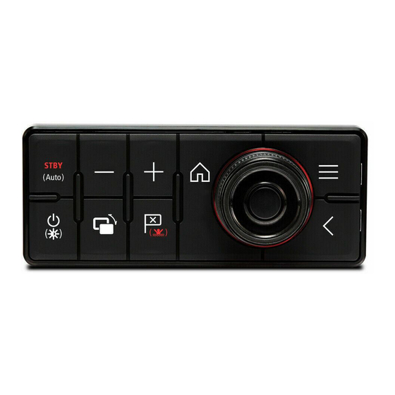
Page 15: Chapter 6: Operation
Chapter 6: Operation 6.1 Keypad controls Note: * Only applicable to eS and gS Series displays. a Series, c Series and e Series Connecting the keypad allows you to control your displays cannot be powered on using the multifunction display remotely. keypad. -
Page 16: Pairing The Keypad
6.2 Pairing the keypad 2. Select Clear Pairings. 3. Select Yes to unpair the keypad with the display. Each keypad can be paired with multiple MFDs and multiple keypads can be connected to the same Unpairing from all displays system. The keypad can be unpaired from all displays With the keypad connected to the MFD: following the steps below. -
Page 17: Chapter 7: System Checks And Troubleshooting
Chapter 7: System checks and troubleshooting 7.1 Keypad status 7.2 PoE troubleshooting The keypad is backlit with LEDs. The LEDs are used If you are experiencing connection issues with to identify the status of the keypad. the remote keypad when powering the device via PoE, consider using the keypad’s dedicated power UniController connector to supply the power to the device. -
Page 18: Power Up Troubleshooting
Software corruption In the unlikely event that the products software has become corrupted please try re-flashing the latest software from the Raymarine website. On display products, as a last resort, you can try to perform a ‘Power on Reset’, however this will delete all settings/presets and user data (such as waypoints and tracks) and revert the unit back to factory defaults. -
Page 19: Chapter 8: Maintenance
Chapter 8: Maintenance 8.1 Service and maintenance This product contains no user serviceable components. Please refer all maintenance and repair to authorized Raymarine dealers. Unauthorized repair may affect your warranty. 8.2 Routine equipment checks Raymarine strongly recommends that you complete a number of routine checks to ensure the correct and reliable operation of your equipment. -
Page 20: Chapter 9: Technical Speci Ication
Chapter 9: Technical speci ication 9.1 Technical specification 9.2 Compliance Power specification The product has been tested to the relevant sections of the standards listed below. PoE class Class 1 Ethernet/PoE • IEEE 802.3 Nominal supply • PoE: 48 V dc voltage •... -
Page 21: Chapter 10: Technical Support
• Software application version. • System diagrams. You can obtain this product information using the menus within your product. Servicing and warranty Raymarine offers dedicated service departments for warranty, service, and repairs. Viewing product information With your MFD Homescreen displayed: 1. Select Set-up. -
Page 22: Learning Resources
Training courses Raymarine regularly runs a range of in-depth training courses to help you make the most of your products. FAQs and Knowledge Base Raymarine has produced an extensive set of FAQs and a Knowledge Base to help you find more information and troubleshoot any issues. -
Page 23: Chapter 11: Spares And Accessories
Chapter 11: Spares and accessories 11.1 Keypad spares and accessories Spares Item Part number Portrait keypad mat spare R70509 Landscape keypad mat spare R70508 Accessories Item Part number Right angled 2 m (6.6 ft) A06070 power cable Straight 2 m (6.6 ft) power A06049 cable... -
Page 24: Raynet To Raynet Cables And Connectors
RayNet to RayNet cables and connectors Description Typical use Quantity Standard RayNet connection cable Suitable for connecting all RayNet equipment directly to with a RayNet (female) socket on both LightHouse multifunction displays featuring a RayNet ends. connector. Can also be used to connect RayNet equipment via a RayNet network switch (e.g. -
Page 25: Raynet To Rj45 Adapter Cables
• E55051 (10 m). • A62135 (15 m). • E55052 (20 m). Adapter cable with a RayNet (female) Directly connect a Raymarine radar scanner with an RJ45 socket on one end, and a waterproof SeaTalk (male) cable to a RayNet network switch (e.g.
Need help?
Do you have a question about the RMK-10 and is the answer not in the manual?
Questions and answers