
Subscribe to Our Youtube Channel
Related Manuals for LPKF ProtoMat S62


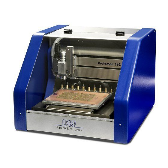
Summary of Contents for LPKF ProtoMat S62
- Page 1 Titelfoto einfügen: Größe: 11,5 cm x 9,5 cm Abstand: oben: 1,5 cm links: 8,5 cm ® ProtoMat Operating Manual 7.1, English...
- Page 3 ® ProtoMat Operating Manual 7.1, English LPKF Laser & Electronics AG Osteriede 7 D-30827 Garbsen Germany Phone ++ 49 - (0) 51 31 - 70 95 - 0 ++ 49 - (0) 51 31 - 70 95 - 90 E-Mail lpkf@lpkf.de...
-
Page 4: Introduction
Any distribution or copying of this manual or parts of this manual in any form and Copyright 2008 LPKF AG use of its contents require the written permission of the LPKF AG. Subject to modifications. Translation of the german original... -
Page 5: Information About This Document
Information about this document This manual contains important information regarding operation, care ® and maintenance of the LPKF circuit board plotter ProtoMat S62. The manual is directed at persons with basic knowledge in the installation and operation of software-controlled machines. Knowledge regarding the safety and behavior in workshops as well as regarding the operation of a computer with Windows 2000/XP are required. - Page 6 [ ] Square brackets indicate that no further steps need to be carried out for this action. Brand names The LPKF Logo, LPKF ProtoMat, BoardMaster and LPKF ProConduct are registered trademarks of LPKF Laser & Electronics AG. Windows is a brand name of the Microsoft AG.
-
Page 7: Table Of Contents
2.5 LPKF dust extraction ........ - Page 8 Switching off the circuit board plotter ......53 Switching off the LPKF dust extraction ......53 4.3 Finding out about BoardMaster .
- Page 9 Table of contents 4.9 Drilling ............73 Drilling a hole .
- Page 10 Table of contents 5.5 Selecting/Setting up a production phase ......99 Selecting the production phase ........99 5.5.1 Selecting tools (optional) .
- Page 11 Table of contents 6.2 Maintaining milling depth limiter and collet chuck ....112 6.2.1 Removing and cleaning the milling depth limiter..... 112 Removing the milling depth limiter .
- Page 12 8.3.2 Consumables ..........144 Technical data 10 LPKF Service 11 EC Declaration of Conformity 12 Index ®...
-
Page 13: List Of Figures
LPKF dust extraction ........ - Page 14 List of figures Fig. 35: BoardMaster message "Drill pass hole?" ....... . 85 Fig.
- Page 15 List of figures Fig. 71: Bore in the camera image window ........134 Fig.
- Page 16 For your notes ® ProtoMat...
-
Page 17: For Your Safety
If, after reading this manual, a situation should arise in which you are not sure how to use or ® service the ProtoMat S62, you should contact LPKF Support or consult a person skilled in the art. 1.1 Designated use ®... - Page 18 Operation of the circuit board plotter is only permitted subject to sufficient dust extraction provision, which must include fine dust filtering. We rec- ommend the use of the LPKF dust extraction with integrated HEPA filter. If you want to use a different system for dust extraction, you should con- tact LPKF Service first.
-
Page 19: Safety Instructions
› Read the installation instructions/operating manual before operating the machine. In case of uncertainties ask a person qualified in the art or contact LPKF Support. › Use the machine only in accordance with its proper use. › Never operate the machine in environments subject to fire or explosion hazards. - Page 20 › Have the machine operated, serviced and repaired by suffi- ciently qualified and authorised personnel only. › Repairs must only be carried out by qualified LPKF personnel or following consultation with LPKF Support. › Keep children away from the work area.
- Page 21 For your safety General safety instructions (Continuation) › If evidence of damage or malfunctions is found, the device must be brought to a standstill immediately. Have any mal- functions rectified immediately. If the damage cannot be put right, the machine must be taken out of operation and secured against being switched on.
- Page 22 For your notes ® ProtoMat...
-
Page 23: What Is What
What is what? 2. What is what? ® In this chapter you get to know the components and operating elements of the ProtoMat S62. Before installing the machine or putting it into operation, first familiarise yourself with the indi- vidual components. 2.1 Circuit board plotter with acoustic cabinet ®... -
Page 24: Fig. 2: Optional Components
Circuit board plotter with acoustic cabinet Optional components Fig. 2: Optional components 1 StatusLight 2 Camera (VisionSystem) 3 Vacuum table ® ProtoMat... -
Page 25: Milling/Drilling Head
What is what? 2.2 Milling/drilling head Fig. 3: Milling/drilling head (front view) Equipment with camera (VisionSystem) Basic equipment 1 Spring adjustment 5 Plastic base of the milling depth limiter, 8 Power supply for the camera alternatively: brush head (accessories) 2 Heat sink 9 Hose for dust extraction 6 Milling depth limiter 3 Lighting connection... -
Page 26: Traversing Table And Tool Magazine
Traversing table and tool magazine 2.3 Traversing table and tool magazine Fig. 4: Traversing table with tool magazine 1 Tool magazine 4 Pass hole strip with pass hole pin 2 Tool position 10 5 Tool position 1 3 Pass hole strip with pass hole pin Fig. -
Page 27: Connecting Elements And Rating Plates
What is what? 2.4 Connecting elements and rating plates Fig. 6: Main switch with mains connection 1 Acoustic cabinet 2 Rating plate 5 Main switch with right side panel removed 3 Fuse holder 6 Acoustic cabinet cover 4 Mains connection Operating Manual 7.1 Rev.: 18.06.2008... -
Page 28: Fig. 7: Dust Extraction And Data Connections
Connecting elements and rating plates Fig. 7: Dust extraction and data connections 1 Acoustic cabinet (rear view) 3 Rating plate 2 Dust extraction 4 Control unit with data connections Fig. 8: Control unit with data connections 1 Not used 7 USB (for service purposes only) 2 StatusLight status signals (option) 8 Data transfer indicator 3 Port 3 (dust extraction) -
Page 29: Lpkf Dust Extraction
Note: The ProtoMat S62 can be equipped with another type of dust extraction. The relevant documentation contains information about function, operation and maintenance. Fig. 9: LPKF dust extrac- tion 1 Extraction force controller 4 Main switch in automatic mode 2 Power supply... - Page 30 For your notes ® ProtoMat...
-
Page 31: What You Should Know
What you should know 3. What you should know ® In this chapter you get to know the functions and operating elements of the ProtoMat S62. Prior to commencing operation, you must first familiarise yourself with the most important ele- ments of the BoardMaster and its various operating modes. -
Page 32: Milling Depth/Width Limitation
The milling/drilling head In the pause position, the milling/drilling head is on the right and the tra- Pause position versing table is at the front. Use the pause position to load the circuit board plotter. The home position serves as the BoardMaster reference point and lies Home position exactly on the mirror axis of the traversing table. -
Page 33: Fig. 12: Milling Width With Universal Cutter And Micro Cutter
- Nominal width, B - Milling width, c - Conical tool (Universal Cutter, Micro Cutter), d - (Cu) laminate, e - Carrier material Always check the milling width at the lower edge of the (copper) laminate to ensure the required electrical isolation between the conductor tracks. Tip: Use the LPKF measuring microscope to check the milling width exactly. Operating Manual 7.1... -
Page 34: The Traversing Table
The traversing table 3.2 The traversing table The traversing table can be moved in the Y direction to position the mill- ing/drilling head in any position above the work area. BoardMaster co- ordinates the traversing motions. Fig. 13: Pass hole system 1 Pass hole strip (red) 3 Traversing table 2 Pass hole pin... -
Page 35: The Pass Hole System
What you should know 3.2.1 The pass hole system ® The ProtoMat S62 is delivered from the factory with a pass hole system for base material in standard size 9" x 12". It comprises two pass hole pins mounted in exchangeable plastic strips. The plastic strips can be used more than once and moved individually in the X direction. -
Page 36: The Tool Magazine
3.4 Usable tools ® The ProtoMat S62 has been designed exclusively for the use of LPKF drilling and milling tools manufactured specifically and equipped with spacer rings. If other tools are used, we cannot guarantee that the circuit board plotter will function without errors, nor can we be held liable for working results. -
Page 37: Surface Tools
What you should know 3.4.1 Surface tools Universal Cutter 1/8" 0.2 - 0.5 mm (8 - 20 mil) Copper Milling insulation clearances of varying widths in cop- Application: per-plated base material. Use the milling depth setting to define the milling width. Orange Colour: Conical... - Page 38 Usable tools End Mill (End Mill 1/8") 0.8 - 3.0 mm 0.8 - 3.0 mm (31 - 118 mil) (31 - 118 mil) Aluminium Copper Aluminium engraving, recesses and wide insula- Application: tion clearances Purple Colour: Cylindrical Shape: d = 0.80 mm (31 mil) Milling widths: d = 1.00 mm (39 mil) d = 2.00 mm (79 mil)
-
Page 39: Penetrative Tools
What you should know 3.4.2 Penetrative tools End mill long (End Mill long 1/8") 1 - 2 mm 1 - 2 mm (39 - 79 mil) (39 - 79 mil) Aluminium Dielectric Contour milling, material cut-outs and depanelisation in Application: aluminium and soft RF and microwave materials. - Page 40 Usable tools Drill (Spiral Drill) min. 0.2 mm max. 3.0 mm (118 mil) (8 mil) Copper Bores penetrating the material. Application: Green Colour: Cylindrical Shape: 0.20 mm (8 mil) 1.40 mm (55 mil) Available diame- ters: 0.30 mm (12 mil) 1.50 mm (59 mil) 0.40 mm (16 mil) 1.60 mm (63 mil)
-
Page 41: The 2.5 D Function
2.5 D mode. For optimum dust extraction, the milling depth limiter base must be replaced with the LPKF brush head (which is available as an accessory) when processing in 2.5 D mode (see chapter ‚ "Dismounting the plastic base/brush head", on page 62). -
Page 42: Manual Operation
Manual operation For tool-friendly material removal/contour milling, the 2.5 D function should be used with the following materials/milling depths: Tab. 1: 2.5 D processing, milling depth and materials Material Milling depth GFK (FR4)/CFK base material PTFE/ceramic composite base material > 2 mm Wood Non-ferrous metals (aluminium, brass) >... -
Page 43: Automatic Operation
These *.LMD files contain information regarding layout, struc- ture and use of the required tools. Tip: Use the tutorial files prepared by LPKF to familiarise yourself with the automatic operation and to produce a double-sided sample circuit board. Detailed information about the tutor data can be found in the ®... -
Page 44: Production Phases
3.7.2 Production phases The following production phases are contained in the phase files: Tab. 3: Production phases 1/2-layer printed circuit boards Plating LPKF ProConduct Galvanic Required phase file 1-2layer + proconduct.phs 1-2layer.phs (<default>) Production phases (Page 1 of 3) ®... - Page 45 What you should know 4-layer printed circuit boards Plating LPKF ProConduct Galvanic Required phase file 4layer + proconduct.phs 4layer.phs Production phases (Page 2 of 3) Operating Manual 7.1 Rev.: 18.06.2008...
- Page 46 Automatic operation Solder stop foils Solder paste templates Required phase file soldermask.phs stencilmilling.phs Production phases 6-layer printed circuit boards Plating Galvanic Required phase file 6layer.phs Production phases (Page 3 of 3) Work steps in the production phases BoardMaster assists you in selecting the next production phase and pro- vides information about the manual operating steps required for produc- tion, for example for turning the base material or pressing the individual ®...
- Page 47 Milling Bottom Info! Galvanic plating galvanic through-hole plating All layers (external with galvanic station) Info! ProConduct Plating with the LPKF ProConduct All layers system Info! MultiPress_work Pressing multiple layers with external All layers multi-layer press Info! Apply foil to PCB...
-
Page 48: Data Selection
Automatic operation 3.7.3 Data selection Production only ever runs with the data you have activated. You can use the selection functions to activate all data or select and acti- vate subsections, individual lines or even individual segments of a line. It is also possible to restrict the selection to one or more tools within a production phase. -
Page 49: Manual Tasks And Settings
This chapter contains essential information about manual operation of the ProtoMat S62. You will find detailed information about the automatic control and operation of the LPKF BoardMas- ter software in the BoardMaster manual. Observe the safety instructions and follow the guid- ances step by step in order to achieve the desired result. -
Page 50: Switching On The Lpkf Dust Extraction (Optional)
› Make sure that the dust extraction for material processing is WARNING switched on (continuous or automatic operating mode). 1. Switch the main switch of the LPKF dust extraction to the desired position. Fig. 17: Dust extraction - operating modes... -
Page 51: Setting The Suction Force (Optional)
Manual tasks and settings II. Setting the suction force (optional) 1. Turn the Speed controller to select the desired suction force. For the optimum operation with low noise pollution we recommend the following settings: – Basic equipment (w i t h o u t vacuum table): Turn the Speed controller to the medium range. -
Page 52: Starting Boardmaster
1. Double click on the BoardMaster symbol on the desktop. Make sure that you start the current BoardMaster version. Click on Start > Programs > LPKF Laser & Electronics > BoardMaster ... Note: Make sure to start the BoardMaster version delivered with the ®... -
Page 53: Checking The Connection Settings (If Necessary)
Manual tasks and settings 4. If there is no tool in the circuit board plotter: – Deactivate all entries. – Enter the value 0 in the field Enter the free tool position:. 5. Click on OK. ® [ ] The ProtoMat S62 is ready for operation. -
Page 54: Switching Off The System
Switching off the system 2. Make sure that the following values are entered: Control: SMCU 2 Machine: ProtoMat S62 Interface type: RS-232 (USB is only intended for service purposes) COM Port: COM port to which the circuit board plotter is connected and which was defined in the Windows system control. -
Page 55: Switching Off The Circuit Board Plotter
S62 is equipped with another dust extraction, famil- iarise yourself with the relevant operation information. 1. Set the main switch of the LPKF dust extraction to the position OFF (centre position). Set the main switch of the LPKF dust extraction to the position Connection to LPKF ProtoMat, to use the dust extraction after ®... -
Page 56: Finding Out About Boardmaster
Finding out about BoardMaster 4.3 Finding out about BoardMaster ® The ProtoMat S62 is controlled by means of the LPKF Software BoardMaster. In the following the user interface and the most important selection and control elements will be explained. 4.3.1 The user interface Fig. - Page 57 Manual tasks and settings The title bar shows the program name, the circuit board plotter used as Title bar well as the name of any loaded or newly created job. The menu bar lists all available menus. Main menu The function bar shows the functions used for manual control of the cir- Function bar cuit board plotter and for starting automatic machining processes.
-
Page 58: Frequently Used Functions
Finding out about BoardMaster 4.3.2 Frequently used functions Frequently used functions can be called from the function bar. Designation Function, note Tool selection list Picking up/setting down the desired tool Only the tools set up in the tool magazine dia- logue box (Tool positions window) are dis- played. - Page 59 Manual tasks and settings Designation Function, note Move to zero Move the milling/drilling head to the zero posi- tion. Move to y+ Move the milling/drilling head horizontally. Move to x- Enter the increment in mm in the input box. Move to x+ Move to y- Move to z+ Move the milling/drilling head vertically.
-
Page 60: Positioning The Milling/Drilling Head
Positioning the milling/drilling head Designation Function, note Move project Move a project on the work area with the mouse. Copy project Copy a project and position the copy on the work area with the mouse. SetFocus Save the vertical position of the milling/drilling head as the focus position. -
Page 61: Moving The Milling/Drilling Head To A Predefined Position
Manual tasks and settings Moving the milling/drilling head to a predefined position To load the circuit board plotter, create a pass hole system or set up the co-ordinate system, the milling/drilling head can be moved to defined positions above the traversing table. 1. -
Page 62: Moving The Milling/Drilling Head Step By Step In The X/Y Direction
Positioning the milling/drilling head Moving the milling/drilling head step by step in the X/Y direction 1. Enter the desired increment in mm in the input box between the arrow buttons (Move to x/y). 2. Click on the button for the desired direction. The milling/drilling head or the traversing table is moved by the entered value in the following direction. -
Page 63: Moving The Milling/Drilling Head Vertically
Manual tasks and settings Moving the milling/drilling head vertically 1. Enter the desired increment in mm in the input box between the buttons Move to z+/z-. 2. Click on the button for the desired direction. Note: If the message "Outside the adjustment range" appears, the desired value is too large. -
Page 64: Mounting/Dismounting The Milling Depth Limiter Base
Mounting/Dismounting the milling depth limiter base 4.5 Mounting/Dismounting the milling depth limiter base In order to ensure that milling will always be performed at the exact working depth, you need to mount the milling depth limiter's plastic base included in the scope of delivery or the brush head which is available to purchase as an accessory. -
Page 65: Mounting The Plastic Base/Brush Head
Manual tasks and settings Mounting the plastic base/brush head 1. Take a firm hold of the milling/drilling head at the top to prevent it lifting in the following and push the plastic base/brush head into the milling depth limiter from below. Fig. -
Page 66: Loading
Loading 4.6 Loading To avoid material damage, the circuit board plotter must only be loaded in the pause position. Health hazard! The swarf and dust generated during material processing can cause eye injuries and allergies. › Extract the swarf and dust or remove them with a brush or mois- WARNING tened cloth. -
Page 67: Defining The Work Area
Manual tasks and settings Setting up the work area To get optimum use of the base material, you first need to define the work area. Thereby the milling depth limiter's plastic base must be located entirely above the base material. Accordingly, when setting up the work area, you must make sure that the milling/drilling head is positioned over the base material with at least 12 mm clearance to the edges of the material to be processed. -
Page 68: Defining The Material Height And Z Values
Loading Defining the material height and z values BoardMaster is factory-set with the following z values: Material thickness: 1.60 mm drilling underlay: 2 mm Moving free height: 2 mm If you wish to use a thinner/thicker material or a different drilling underlay, you will need to modify the values accordingly. -
Page 69: Setting Up Tools
Manual tasks and settings 4.6.2 Setting up tools Before you load the tool magazine, you need to define a unique position for each tool in it. I. Opening the tool magazine dialogue box 1. Click on the button for the Toolbox dialog. 2. -
Page 70: Assigning Tool Positions
Loading You can select one tool in each of the tool selection lists under Tool (2). Each selection list contains all available tools. Note: The most recently selected tools always appear as the default selections. If you have already loaded a job, the required tools will be marked * or + in the selection lists. -
Page 71: Fig. 26: Defined Tool Positions
Manual tasks and settings Fig. 26: Defined tool positions Note: The order of the tool positions can be selected at will. During opera- tion, the tools are taken out of the correct tool holder automatically. [ ] Once set up, the tools are displayed in the tool selection list on the func- tion bar. -
Page 72: Inserting Tools
Selecting a tool for processing 4.6.3 Inserting tools Risk of injury! The tools to be used are very sharp edged and can cause cuts and stab injuries. › Handle tools carefully and keep them in the toolbox when not in WARNING use. -
Page 73: Picking Up/Setting Down A Tool
Manual tasks and settings Picking up/Setting down a tool 1. Select the desired tool in the tool selection list. If there is still a tool in the milling/drilling head, it will be set down first. The desired tool is then taken up and the milling/drilling head pauses above the tool holder. -
Page 74: Adjusting The Focus Position
Setting the focus (VisionSystem only) Adjusting the focus position To set the focus position, the material to be used must be loaded. 1. Move the milling/drilling head so that the camera is positioned above an as high-contrast area as possible, e.g. a bore, or at the edge of a milling. -
Page 75: Drilling
Manual tasks and settings 4.9 Drilling Health hazard! The processing of the materials can give rise to dusts and gases hazardous to your health. WARNING › You must switch on the dust extraction before processing mate- rials of any type. Extract the dust and material residues or remove them with a brush or moistened cloth;... -
Page 76: Milling
Milling 5. Move the milling/drilling head as necessary to drill more holes with the same drill. Click on the Motor off button. [ ] The milling/drilling spindle and the dust extraction (automatic mode only) are switched off. 4.10 Milling Health hazard! The processing of the materials can give rise to dusts and gases hazardous to your health. -
Page 77: Creating A Milling Track
Manual tasks and settings Creating a milling track 1. Select the desired mill in the tool selection list. The mill is taken out of the tool magazine and the milling/drilling head pauses above the tool holder. 2. Move the milling/drilling head with the mouse or the Move to x/y buttons to the starting point of the desired milling track . -
Page 78: Adjusting The Milling Depth (Cylindrical Tools)
Milling Adjusting the milling depth/width By means ofthe milling/drilling depth limiter the surface removal can be set exactly to the desired rate. For conical formed mills (Universal Cutter, Micro Cutter), the milling width has to be set using the milling depth limiter. Adjusting the milling depth (cylindrical tools) 1. -
Page 79: Creating A Pass Hole System (Basic Equipment)
Manual tasks and settings 4.11 Creating a pass hole system (basic equipment) ® The ProtoMat S62 traversing table is factory-set with a pass hole sys- tem for standard material sizes (9" x 12"). If, after a period of time, the pass hole pins are not seated free of play anymore, you will need to cre- ate a new pass hole system. -
Page 80: Drilling Pass Holes Into Pass Hole Strips
Creating a pass hole system (basic equipment) 3. Preparing the traversing table: – Remove the drilling underlay from the traversing table. – Pull the pass hole pins out of the red plastic strips using a collet. – Move the plastic strips in the guide groove so that the new pass holes can be positioned as appropriate for the size of your mate- rial. -
Page 81: Fig. 30: Boardmaster Message "Depth Limiter Removed
8. Make a note of the x value. Note: LPKF base materials have a pass hole clearance of 295 mm. 9. Click on the Lower head button to drill the pass hole. 10. Click on the Motor off button. -
Page 82: Drilling Pass Holes Into The Drilling Underlay
Creating a pass hole system (basic equipment) Drilling pass holes into the drilling underlay To drill pass holes into the drilling underlay, the Spiral Drill 3.0 mm must be set up and positioned accordingly in the tool magazine. 1. Mount the plastic base on the milling depth limiter (see "Mounting the plastic base/brush head"... -
Page 83: Creating A Pass Hole System For The Vacuum Table
Manual tasks and settings 11. Click on the Lower head button to drill the pass hole. 12. Click on the Motor off button. [ ] To complete the pass hole system, you simply need to insert the pass hole pins (see chapter 4.13‚ "Inserting pass hole pins", on page 88) and mount the plastic base on the milling depth limiter(see "Mounting the plastic base/brush head"). -
Page 84: Preparing The Circuit Board Plotter And Vacuum Table
Creating a pass hole system for the vacuum table Preparing the circuit board plotter and vacuum table Before you can drill the pass holes, you need to prepare the circuit board plotter: 1. Carefully squeeze the milling depth limiter's plastic base and pull it down and out of the milling/drilling head. -
Page 85: Drilling Pass Holes Into Pass Hole Strips
Manual tasks and settings 4.12.1 Drilling pass holes into pass hole strips I. Setting parameters for drilling pass holes 1. Select the Spiral Drill Ref. 2.95 mm drill from the Tool selection list. 2. Click on the Tool Lbrary button. The Mill/Drill Tool Edit window is opens. -
Page 86: Setting The Machine Parameters For Drilling Pass Hole Strips
Creating a pass hole system for the vacuum table II. Setting the machine parameters for drilling pass hole strips 1. In the main menu, click on Configuration > Settings..The Machine settings window opens. 2. Click on Unlock. 3. Enter the value 11 in the Vacuum table height [mm] input box. 4. -
Page 87: Fig. 35: Boardmaster Message "Drill Pass Hole
Manual tasks and settings Fig. 35: BoardMaster mes- sage "Drill pass hole?" 6. Click on Yes. A prompt asking if the depth limiter has been removed appears. Fig. 36: BoardMaster mes- sage "Depth limit- er removed" 7. Check that the plastic base has been removed from the milling depth limiter and click on Yes. -
Page 88: Drilling Pass Holes Into The Sinter Plate
For your notes 4.12.2 Drilling pass holes into the sinter plate Before drilling pass holes into the sinter plate, the machine parameters have to be adjusted. I. Adjusting machine parameters 1. Put the the sinter plate on to the vaccum table. 2. -
Page 89: Drilling Pass Holes Into The Sinter Plate
Manual tasks and settings II. Drilling pass holes into the sinter plate 1. On the function bar, click on the tool selection list and select the entry 2. Spiral Drill Ref 2.95 mm. Fig. 38: Selecting pass hole drills for pass hole strips 2. -
Page 90: Inserting Pass Hole Pins
Inserting pass hole pins 10. If the dust extraction does not shut down automatically, click on the button on the function bar. Vacuum off 11. On the menu bar, click on the Move to pause button. The milling/drilling head moves to the pause position. 12. -
Page 91: Inserting Pass Hole Pins
Manual tasks and settings Inserting pass hole pins 1. Insert a pass hole pin with the rounded end into the press-in tool (the bevelled end must stick out). Fig. 39: Press-in tool with pass hole pin 2. With the press-in tool press the pass hole pin as far as it will go into the desired bore of the pass hole strip. - Page 92 Inserting pass hole pins ® ProtoMat...
-
Page 93: Working Sequence In Automatic Mode
ProtoMat S62 and your individual requirements. If you are working with the LPKF circuit board plotter for the first time, we recommend that you start by practising the procedures described with the example files included in the delivery. -
Page 94: Setting Up A Job
Phase file Single-sided/double-sided printed circuit 1-2layer.phs (<default>) boards (galvanic through-hole plating) Single-sided/double-sided printed circuit 1-2layer + proconduct.phs boards (galvanic through-hole plating with LPKF ProConduct) 4-layer multi-layer 4-layer.phs (galvanic through-hole plating) 4-layer multi-layer 4-layer + proconduct.phs (galvanic through-hole plating with LPKF... -
Page 95: Creating A New Job
Working sequence in automatic mode Creating a new job 1. Click on File > Import > LMD/LPR..The Import Project window will appear. 2. Select a project (*.LMD file). 3. Click on Open. The selected project will be placed in the centre of the work area. 4. -
Page 96: Aligning/Distributing Projects
Setting up a job Aligning/Distributing projects To make optimum use of the base material, you can align, distribute and duplicate projects individually. 1. On the function bar, click on the Move instance button to move a project on the work area. On the function bar, click on the Copy instance button to copy a project and move the copy on the work area. -
Page 97: Saving A Job
Working sequence in automatic mode Saving a job If you have have set up an already existing job, you can save it under a different name or the current version can be overwritten. 1. To save the job under a new name: Click on File >... -
Page 98: Opening The Tool Positions Input Window
Setting up the tools I. Opening the Tool Positions input window 1. Click on the Toolbox dialog button. 2. Click on Yes to move the milling/drilling head to the pause position. The Tool Positions input window opens. Fig. 41: Tool Positions input window 1 Position in the tool magazine 3 Service life of the tools required for the current... -
Page 99: Configuring Tools In The Tool Magazine
Working sequence in automatic mode The tools required for the job are displayed in the Wanted for current job (phase) box. The preceding numbers designate the tools required for the current phase (displayed on the function bar). The numerical value indicates the service life required for the job in mm (milling cutter) or the number of bores (drill). -
Page 100: Inserting Tools
Setting up the tools Note: The order of the tool positions can be selected at will. During opera- tion, the tools are taken out of the correct tool holder automatically. 2. To adjust the manual milling depth setting after each tool change during a production phase: Activate the Stop at tool exchange checkbox. -
Page 101: Selecting/Setting Up A Production Phase
Working sequence in automatic mode 5.5 Selecting/Setting up a production phase Each production phase has to be selected and, if necessary, set up man- ually. BoardMaster assists you in selecting the next production phase and provides information on required manual operating steps. We recom- mend absolute compliance with the specified order, since some produc- tions phase follow on one from the other while sonme previous phases may not be processed later on. -
Page 102: Selecting Tools
Selecting/Setting up a production phase Selecting tools 1. Click on Edit > Tool Selection..The Select Tools window will be opened. Fig. 44: Selecting tools 2. In the Sel. column, click on the check box to activate or deactivate a tool. Once activated, a tool is identified by a check mark in the check box. -
Page 103: Activating Data
Working sequence in automatic mode 5.5.2 Activating data During a production phase, only activated data elements will be pro- duced. You can activate data elements in the following ways: • All data • Areas of data elements – including all associated segments –... -
Page 104: Activating Data Segments By Index Number
Selecting/Setting up a production phase Activating data segments by index number 1. To activate one individual data segment: – Enter the number of the desired data segment into the Segment number input field. – Click on the [ ] button. –... -
Page 105: Setting Up 2.5 D Processing (Optional)
5.6 Setting up 2.5 D processing (optional) Conditions: • The plastic base of the milling depth limiter is replaced with the LPKF brush head, which is available as an accessory (see chapter 4.5‚ "Mounting/Dismounting the milling depth limiter base", on page 62). -
Page 106: Setting Up Contour Milling With 2.5 D Mode
Setting up 2.5 D processing (optional) 5.6.1 Setting up contour milling with 2.5 D mode I. Activating the 2.5 D mode for a phase 1. On the function bar, click on the Phase configuration button. The Phases window appears. Fig. 45: Activating the 2.5 D mode in the phases dialogue 2. -
Page 107: Setting The Moving-Free Height
[ ] As soon as the production phase starts, the 2.5 D mode window will be opened. 5.6.2 Setting up surface milling with 2.5 D mode To process surfaces in 2.5 D mode, you need the vacuum table. For detailed information about the specific workflow, please contact the LPKF Support. Operating Manual 7.1 Rev.: 18.06.2008... -
Page 108: Starting Production
Starting production 5.7 Starting production In the Phase selection list (on the function bar), always the current (most recently processed) production phase is displayed. If a production phase is finished (all activated data has been executed), you first have to select the next production phase and must activate the desired data. -
Page 109: Milling Contours In 2.5 D Mode (Optional)
Working sequence in automatic mode Milling contours in 2.5 D mode (optional) If you have activated 2.5 D mode, the 2.5 D mode window will be opened after the start of the production phase. Fig. 47: 2.5 D mode: Con- figuring 1. -
Page 110: Adjusting The Milling Depth/Width
Starting production Adjusting the milling depth/width If you activated the Stop after change option when setting up the tools, the "Stop for depth adjustment ?" message will appear after a milling tool has been picked up. 1. In order to adjust the milling depth on the basis of a sample milling: Click on Yes. -
Page 111: Stopping The Production Phase
Working sequence in automatic mode 5.7.1 Stopping the production phase A production phase can be interrupted at any time and resumed subse- quently. Production based on data already sent to the circuit board plotter will be completed. Interrupting the production phase 1. -
Page 112: Aborting Production
Ending production 2. Save the job under a new name (see "Saving a job" on page 83). If at all possible, choose a name reflecting the current production status, e.g. MyJobDrillingBottom.job. [ ] The job can be saved with the current processing status and then opened and resumed subsequently. -
Page 113: Care And Maintenance
ProtoMat S62 and all connecting cables for damage. 2. If you notice damage, have it made good by a professional prior to next use. If necessary, contact the LPKF Support. Make sure that ® the ProtoMat S62 can not be used until the damage has been repaired. -
Page 114: Maintaining Milling Depth Limiter And Collet Chuck
Maintaining milling depth limiter and collet chuck 6.2 Maintaining milling depth limiter and collet chuck The milling depth limiter and collet chuck must be cleaned at regular intervals after 100 operating hours and whenever necessary. These com- ponents need to be removed for cleaning. Required tools and materials: •... -
Page 115: Fig. 51: Dismantling The Milling Depth Limiter
Care and maintenance 2. Move the milling/drilling head to the zero position. 3. Move the milling/drilling head 150 mm to the right. 4. Pull the extraction hose off the milling/drilling head (1). 5. Disconnect the plug for the head lighting (2). Fig. -
Page 116: Cleaning The Milling Depth Limiter
Maintaining milling depth limiter and collet chuck II. Cleaning the milling depth limiter 1. Carefully squeeze the plastic base and pull it out of the milling depth limiter. 2. Unscrew the setting wheel from the milling depth limiter. 3. Clean all parts with a brush or a lint-free cloth. 4. -
Page 117: Fig. 53: Setting The Milling/Drilling Head Offset
Care and maintenance Fig. 53: Setting the mill- ing/drilling head offset 5. Enter bmaster as the service password. 6. Click on OK. The service functions can be selected. In the Main/Aux. clamp box, click on Open. The collet chuck is opened. [ ] Now you can remove the collet chuck. -
Page 118: Removing The Collet Chuck
Maintaining milling depth limiter and collet chuck II. Removing the collet chuck Risk of injury caused by pointed/sharp edged tools! The tool required for unsrewing the collet chuck can cause cuts and stab injuries. › Handle the tool carefully. WARNING 1. -
Page 119: Cleaning The Collet Chuck And The Collet Chuck Holder
Care and maintenance III. Cleaning the collet chuck and the collet chuck holder 1. Insert the collet chuck brush into the collet chuck and push/turn the brush repeatedly to remove the dust particles. Fig. 56: Cleaning the collet chuck holder 2. -
Page 120: Mounting The Collet Chuck And The Milling Depth Limiter
Maintaining milling depth limiter and collet chuck 6.2.3 Mounting the collet chuck and the milling depth limiter Always screw in the collet chuck before mounting the milling depth limiter. I. Screwing in the collet chuck Risk of injury caused by pointed/sharp edged tools! The tool required for unsrewing the collet chuck can cause cuts and stab injuries. -
Page 121: Replacing Fuses
Care and maintenance 6.3 Replacing fuses The circuit board plotter is protected by two T4L 250 V fuses. To replace the fuses, you first need to remove the side wall of the acoustic cabinet. I. Removing the side wall of the acoustic cabinet 1. -
Page 122: Replacing The Fuses
Replacing fuses II. Replacing the fuses Risk of death! Missing or insufficient electrical fuse protection can result in fatal electric shocks and/or fire. › Use only fuses of type T4L 250 V. WARNING › Fuse holders must be bridged. N E V E R The fuse holder is located under the mains connecting socket. -
Page 123: Mounting The Side Wall Of The Acoustic Cabinet
Care and maintenance III. Mounting the side wall of the acoustic cabinet 1. Slip on the side wall of the acoustic cabinet from the side. 2. Fix the side wall in place with the eight TORX screws. 6.4 Configuring the tool holder position If the tool is not picked up/set down correctly, the tool holder position must be determined and reintegrated into the co-ordinate system. -
Page 124: Activating The Service Functions
Configuring the tool holder position Fig. 60: Setting the mill- ing/drilling head offset 4. Make sure that for both X and Y a 0 is entered into the input boxes. 5. Click on OK. The offset is set correctly. II. Activating the service functions ›... -
Page 125: Fig. 61: Setting The Milling/Drilling Head Offset
Care and maintenance Fig. 61: Setting the mill- ing/drilling head offset 2. Enter bmaster as the service password. › Click on OK. The service functions can be executed now. Fig. 62: Tool Box with service functions Operating Manual 7.1 Rev.: 18.06.2008... -
Page 126: Testing The Tool Holder Position
Configuring the tool holder position III. Testing the tool holder position 1. In the Main/Aux. Clamp field, click on Open. The collet chuck opens. 2. In the Pos. column of the tool list, click on the tool position to be checked. -
Page 127: Correcting The Tool Holder Position
Care and maintenance IV. Correcting the tool holder position 1. Click on Move to z+ to lift the milling/drilling head. 2. Use the Move to x/y buttons with 0.1 mm steps to correct the posi- tion of the milling/drilling head above the tool magazine. Click on Move to z-. -
Page 128: Determining The Tool Holder Position With Visionsystem
Configuring the tool holder position 6.4.2 Determining the tool holder position with VisionSystem To configure the tool changing positions with the optional VisionSystem, proceed as follows: I. Setting the camera offset 1. Select a 0.8 mm drill and drill a hole in an unused area of the base material. -
Page 129: Fig. 64: Positioning The Camera Image Above The Bore
Care and maintenance 6. Click on Move to > Camera >> Head in the main menu. The camera is positioned above the bore. 7. Enter the value 0.005 (mm) in the Move to X/Y input box for the increment and position the milling/drilling head with the arrow keys so that the cross-hairs of the camera image are positioned exactly in the centre of the bore. -
Page 130: Preparing The Tool Magazine For Determining The Position
Configuring the tool holder position 8. Click on Head to apply the new position. The new co-ordinates are displayed in the Offset [mm] field. Fig. 65: Setting the mill- ing/drilling head offset 9. Click on OK. [ ] The camera offset is set correctly. II. -
Page 131: Calling The Service Functions
Care and maintenance III. Calling the service functions 1. Click on Configuration > Toolbox..The tool magazine window is opened. 2. Click on Service. The Enter service password dialogue box is opened. Fig. 67: Setting the mill- ing/drilling head offset 3. -
Page 132: Reading In The Position Data
Configuring the tool holder position Fig. 68: Tool magazine with service functions IV. Reading in the position data 1. In the Pos. column, click on the tool position to be read in. 2. Click on Check. The milling/drilling head moves to the selected tool position. 3. -
Page 133: Adjusting The Camera (Only With Visionsystem)
Care and maintenance 4. In the tool magazine window, click on Accept. The co-ordinates determined are applied to the changing position. 5. Repeat the test and correction functions as necessary for all tool positions. 6. Click on OK to close the Tool magazine window. 7. -
Page 134: Setting The Camera Offset
Adjusting the camera (only with VisionSystem) Setting the camera offset 1. Drill a 0.8 mm hole into an unused area of the base material. Take care not to move the milling/drilling head further, since the current position serves as the reference point. 2. -
Page 135: Fig. 70: Positioning The Camera Above The Bore
Care and maintenance 7. Move the head with the arrow keys until the cross-hairs of the cam- era image are exactly in the centre of the bore. Reduce the increment to 0.005 mm for more precise positioning. Fig. 70: Positioning the camera above the bore n the main menu, click on Configuration >... -
Page 136: Calibrating Fiducial Recognition
Adjusting the camera (only with VisionSystem) 6.5.1 Calibrating fiducial recognition Fiducial recognition is factory-set for bores 1.5 mm in diameter. The set- tings must be recalibrated if the fiducials are not clearly recognised. I. Preparing the fiducial recognition 1. Drill a hole into an unused area of the material to be used with the Spiral Drill 1.5 mm. -
Page 137: Fig. 72: Setting Fiducial Recognition
Care and maintenance Fig. 72: Setting fiducial rec- ognition 4. Click on Calibrate camera. 5. The Calibration window is opened. Fig. 73: Fiducial calibration the value 1.5 into the Diameter input box. Enter 7. Click on Calibrate. Operating Manual 7.1 Rev.: 18.06.2008... -
Page 138: Fig. 74: Calibration Not Possible
Adjusting the camera (only with VisionSystem) 8. If the message "Calibration not possible !" appears: Fig. 74: Calibration not pos- sible – Click on OK. – Check/correct the camera focus and the image brightness and repeat the calibration. 9. Once the calibration has been completed successfully, the mes- sage "Calibration successful!"... -
Page 139: Determining The Fiducial Diameter
Care and maintenance Determining the fiducial diameter The measuring function in the Camera image window can be used to ascertain which value is being measured by BoardMaster at the selected fiducial. 1. To use the measuring function, click on the left edge of the bore with the left mouse button. -
Page 140: Fig. 77: Fiducial Settings
Adjusting the camera (only with VisionSystem) 5. In the Fiducial diameter input box enter the measured value of the bore . Fig. 77: Fiducial settings The value in the Minimal diamer [mm] input box must be smaller than the fiducial diameter by 0.1 mm. 6. -
Page 141: Fig. 79: Calibration Complete
Care and maintenance The message „Calibration complete!“ should appear. Fig. 79: Calibration com- plete 11. Click on OK. 12. In the Setting window, click on OK to save the settings. 13. In the Camera Image window, click on Setting, to open the Set- ting window again. -
Page 142: Changing The Dust Extraction Filter
For your notes [ ] If you now measure the drilled fiducial again, BoardMaster should display the correct value of 1.5. Fig. 81: Measured values in the camera image The f iducial recognition set-up is complete. 6.6 Changing the dust extraction filter The dust extraction filter must be changed regularly. -
Page 143: Error Messages/Malfunctions
Error messages/Malfunctions 7. Error messages/Malfunctions This chapter provides information about possible malfunctions and error messages. You should follow the instructions for troubleshooting in the order specified; they provide you with the quickest route to a possible solution. Error message Possible cause Remedy Fault description Notes... - Page 144 Error messages/Malfunctions Error message Possible cause Remedy Fault description Notes The milling/drilling head interlocks The tool has not been inserted Press the tool as far as it will go with the tool during a tool change. correctly. into the tool holder. The tool is loose in the tool holder.
-
Page 145: Decommissioning, Transport, Disposal
Decommissioning, transport, disposal 8. Decommissioning, transport, disposal This chapter contains important information about safe decommissioning and environmentally- ® friendly disposal of the ProtoMat S62. 8.1 Decommissioning ® I. Switching the ProtoMat S62 off. 1. Click on File > Exit and follow the on-screen instructions. BoardMaster shuts down. -
Page 146: Transport
ProtoMat S62. If you no longer have these, please ask LPKF Service about possible solutions for transportation. Note: LPKF will not accept liability for damage caused by improper trans- port protection. Fitting transport braces 1. Carefully lift up the milling/drilling head and place the foam separa- tor between the traversing/vacuum table and the milling/drilling head. -
Page 147: Technical Data
Technical data 9. Technical data ® ProtoMat Operating voltage 220 – 240 V; 50 Hz – 60 Hz (manually changeable) 110 V – 120 V; 50 Hz – 60 Hz Power consumption 200 W Weight (without/with cover) 55 kg (121 lb) Dimensions (W ×... - Page 148 For your notes ® ProtoMat...
-
Page 149: Lpkf Service
LPKF Service 10. LPKF Service Sales and service contact details are listed below. Our expert team would be delighted to assist you. Europe (LPKF head office) Tel. +49 (0) 5131-7095-0 Fax +49 (0) 5131-7095-90 E-mail rp.sales@lpkf.de rp.support@lpkf.de LPKF Internet site www.lpkf.de www.lpkf.com... - Page 150 For your notes ® ProtoMat...
-
Page 151: Ec Declaration Of Conformity
EC Declaration of Conformity 11. EC Declaration of Conformity Declaration of Conformity in accordance with Machinery Directive 98/37/EC, Appendix II A The manufacturer/seller LPKF Laser & Electronics AG Osterriede 7 30827 Garbsen Germany hereby declares that the circuit board plotter ®... - Page 152 EC Declaration of Conformity • EN 61000-6-1-4:2001 Electromagnetic compatibility (EMC) • EN 55022:1994 A2 Information technology equipment - Radio disturbance characteris- tics - Limits and methods of measurement Amendment A2:1997 Other EU directives applied • EMC Directive 89/336/EEC • Low-Voltage Directive 2006/95/EEC Town: Garbsen Date:...
-
Page 153: Index
Index 12. Index Numeric 1-2layer.phs Data 42, 92 2.5 D function activating 2.5 D processing deactivating 4-layer.phs Data selection 43, 92 6-layer.phs Data transfer indicator 6layer.phs Declaration of Conformity Decommissioning Deep milling ABS copolymers Defined positions Acoustic cabinet Depanelisation mounting the side wall Directives removing the side wall Dismounting the brush head... - Page 154 Moving Lighting connection Multi-layer press Lines Multi-stage milling select all select in area Loading 34, 64 Non-ferrous metals LPKF ProConduct Notations Machinery Directive Options Main menu 54, 55 Outer layers Main switch 21, 25, 53, 120, 143 Mains connection Maintenance...
- Page 155 Production type Suction force defining Surface tools 34, 35 Production types Switching on Project Circuit board plotter copy LPKF dust extraction move Switching the extractor system on/off Projects aligning/distributing Technical data Proper use Title bar Protective foil 54, 55 Tool diameter...
- Page 156 For your notes ® ProtoMat...
Need help?
Do you have a question about the ProtoMat S62 and is the answer not in the manual?
Questions and answers