Sign In
Upload
Manuals
Brands
LPKF Manuals
Plotter
ProtoMat S62
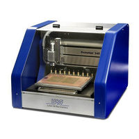
LPKF ProtoMat S62 Manuals
Manuals and User Guides for LPKF ProtoMat S62. We have
2
LPKF ProtoMat S62 manuals available for free PDF download: Operating Manual, Service Manual
LPKF ProtoMat S62 Operating Manual (156 pages)
Brand:
LPKF
| Category:
Plotter
| Size: 3 MB
Table of Contents
Introduction
4
Information about this Document
5
Table of Contents
7
List of Figures
13
1 For Your Safety
17
Designated Use
17
Safety Instructions
19
Fig. 1: Protomat ® S62 Basic Equipment
23
What I What?
23
2 What Is What
23
Circuit Board Plotter with Acoustic Cabinet
23
Fig. 2: Optional Components
24
Milling/Drilling Head
25
Fig. 3: Milling/Drilling Head (Front View)
25
Traversing Table and Tool Magazine
26
Fig. 4: Traversing Table with Tool Magazine
26
Fig. 5: Vacuum Table (Optional)
26
Connecting Elements and Rating Plates
27
Fig. 6: Main Switch with Mains Connection
27
Fig. 7: Dust Extraction and Data Connections
28
Fig. 8: Control Unit with Data Connections
28
LPKF Dust Extraction
29
Fig. 9: LPKF Dust Extraction
29
Fig. 10: Defined Positions of the Milling/Drilling Head
31
Milling Depth/Width Limitation
32
3 What You Should Know
31
The Milling/Drilling Head
31
Defined Positions
31
Fig. 11: Setting Wheel for Milling Depth Limiter
32
Fig. 12: Milling Width with Universal Cutter and Micro Cutter
33
The Traversing Table
34
Fig. 13: Pass Hole System
34
The Pass Hole System
35
Material Fastening
35
Fig. 14: Turning the Material through the Mirror Axis
35
The Tool Magazine
36
Usable Tools
36
Fig. 15: Tool Positions
36
Surface Tools
37
Penetrative Tools
39
The 2.5 D Function
41
Fig. 16: 2,5 D Processing (Application Examples))
41
Manual Operation
42
Automatic Operation
43
Production Types and Phase Files
43
Production Phases
44
Data Selection
48
4 Manual Tasks and Settings
49
Switching on the System
49
Switching on the LPKF Dust Extraction (Optional)
50
Fig. 17: Dust Extraction - Operating Modes
50
Setting the Suction Force (Optional)
51
Switching on the Circuit Board Plotter
51
Starting Boardmaster
52
Fig. 18: Dialog Box Tool Status
52
Checking the Connection Settings (if Necessary)
53
Fig. 19: Input Window Connect
53
Switching off the System
54
Quitting Boardmaster
54
Switching off the Circuit Board Plotter
55
Switching off the LPKF Dust Extraction
55
Finding out about Boardmaster
56
The User Interface
56
Fig. 20: Boardmaster User Interface
56
Frequently Used Functions
58
Positioning the Milling/Drilling Head
60
Moving the Milling/Drilling Head to a Predefined Position
61
Moving the Milling/Drilling Head Step by Step in the X/Y Direction
62
Moving the Milling/Drilling Head with the Mouse
62
Moving the Milling/Drilling Head Vertically
63
Mounting/Dismounting the Milling Depth Limiter Base
64
Dismounting the Plastic Base/Brush Head
64
Fig. 21: Removing the Plastic Base from the Milling Depth Limiter
64
Mounting the Plastic Base/Brush Head
65
Fig. 22: Fitting the Plastic Base on the Milling Depth Limiter
65
Loading
66
Loading and Setting up the Base Material
66
Loading Base Material
66
Defining the Work Area
67
Defining the Material Height and Z Values
68
Fig. 23: Defining the Material Size and Position
68
Setting up Tools
69
Opening the Tool Magazine Dialogue Box
69
Fig. 24: Tool Positions Input Window
69
Assigning Tool Positions
70
Fig. 25: Assigning Tool Positions
70
Fig. 26: Defined Tool Positions
71
Inserting Tools
72
Selecting a Tool for Processing
72
Picking Up/Setting down a Tool
73
Setting the Focus (Visionsystem Only)
73
Setting the Focus to the Saved Value
73
Adjusting the Focus Position
74
Fig. 27: Adjusting the Focus Position
74
Drilling
75
Drilling a Hole
75
Milling
76
Creating a Milling Track
77
Adjusting the Milling Depth (Cylindrical Tools)
78
Adjusting the Milling Width (Universal Cutter and Micro Cutter Only)
78
Creating a Pass Hole System (Basic Equipment)
79
Preparing the Circuit Board Plotter
79
Drilling Pass Holes into Pass Hole Strips
80
Fig. 28: Selecting Pass Hole Drills for Pass Hole Strips
80
Fig. 29: Boardmaster Message "Drill Pass Hole
80
Fig. 30: Boardmaster Message "Depth Limiter Removed
81
Drilling Pass Holes into the Drilling Underlay
82
Fig. 31: Selecting Pass Hole Drills for Base Material/Drilling Underlay
82
Creating a Pass Hole System for the Vacuum Table
83
Preparing the Circuit Board Plotter and Vacuum Table
84
Fig. 32: Pass Hole Strips in the Vacuum Table
84
Drilling Pass Holes into Pass Hole Strips
85
Setting Parameters for Drilling Pass Holes
85
Fig. 33: Setting Parameters for Drilling Pass Holes
85
Setting the Machine Parameters for Drilling Pass Hole Strips
86
Drilling Pass Holes into Pass Hole Strips
86
Fig. 34: Selecting Pass Hole Drills for Pass Hole Strips
86
Fig. 35: Boardmaster Message "Drill Pass Hole
87
Fig. 36: Boardmaster Message "Depth Limiter Removed
87
Drilling Pass Holes into the Sinter Plate
88
Adjusting Machine Parameters
88
Fig. 37: Machine Parameters
88
Drilling Pass Holes into the Sinter Plate
89
Fig. 38: Selecting Pass Hole Drills for Pass Hole Strips
89
Inserting Pass Hole Pins
90
Inserting Pass Hole Pins
91
Fig. 39: Press-In Tool with Pass Hole Pin
91
5 Working Sequence in Automatic Mode
93
Preparation
93
Defining the Production Type
93
Selecting a Phase File
93
Setting up a Job
94
Creating a New Job
95
Opening an Existing Job
95
Aligning/Distributing Projects
96
Fig. 40: Positioning a Project
96
Saving a Job
97
Setting up the Tools
97
Opening the Tool Positions Input Window
98
Fig. 41: Tool Positions Input Window
98
Configuring Tools in the Tool Magazine
99
Fig. 42: Assigning Tool Positions
99
Fig. 43: Defined Tool Positions
99
Inserting Tools
100
Selecting/Setting up a Production Phase
101
Selecting the Production Phase
101
Selecting Tools (Optional)
101
Selecting Tools
102
Fig. 44: Selecting Tools
102
Activating Data
103
Activating All Data
103
Activating Areas of Data Elements
103
Activating Data Segments by Index Number
104
Deactivating All Data
104
Deactivating Data Areas
104
Setting up 2.5 D Processing (Optional)
105
Setting up Contour Milling with 2.5 D Mode
106
Activating the 2.5 D Mode for a Phase
106
Fig. 45: Activating the 2.5 D Mode in the Phases Dialogue Box
106
Setting the Moving-Free Height
107
Setting up Surface Milling with 2.5 D Mode
107
Fig. 46: Setting the Moving-Free Height
107
Starting Production
108
Starting a Production Phase
108
Milling Contours in 2.5 D Mode (Optional)
109
Fig. 47: 2.5 D Mode: Configuring
109
Adjusting the Milling Depth/Width
110
Fig. 48: Adjusting the Milling Width
110
Stopping the Production Phase
111
Interrupting the Production Phase
111
Ending Production
111
Saving the Production Status
111
Aborting Production
112
Fig. 49: Message When Aborting Production
112
6 Care and Maintenance
113
Caring/Inspecting
113
Cleaning the Surfaces
113
Carrying out a Visual Inspection
113
Maintaining Milling Depth Limiter and Collet Chuck
114
Removing and Cleaning the Milling Depth Limiter
114
Removing the Milling Depth Limiter
114
Fig. 50: Collet Chuck Tools
114
Fig. 51: Dismantling the Milling Depth Limiter
115
Fig. 52: Dismantling the Milling Depth Limiter
115
Cleaning the Milling Depth Limiter
116
Removing and Cleaning the Collet Chuck
116
Opening the Collet Chuck
116
Fig. 53: Setting the Milling/Drilling Head Offset
117
Removing the Collet Chuck
118
Fig. 54: Tool with Collet Chuck Wrench
118
Fig. 55: Unscrewing the Collet Chuck
118
Cleaning the Collet Chuck and the Collet Chuck Holder
119
Fig. 56: Cleaning the Collet Chuck Holder
119
Fig. 57: Cleaning the Collet Chuck Holder
119
Mounting the Collet Chuck and the Milling Depth Limiter
120
Screwing in the Collet Chuck
120
Mounting the Milling Depth Limiter
120
Replacing Fuses
121
Removing the Side Wall of the Acoustic Cabinet
121
Fig. 58: Removing the Side Wall of the Acoustic Cabinet
121
Replacing the Fuses
122
Fig. 59: Orientation of the Fuse Holder
122
Mounting the Side Wall of the Acoustic Cabinet
123
Configuring the Tool Holder Position
123
Configuring the Tool Holder Position (Without Camera)
123
Defining the Milling/Drilling Head Offset
123
Activating the Service Functions
124
Fig. 60: Setting the Milling/Drilling Head Offset
124
Fig. 61: Setting the Milling/Drilling Head Offset
125
Fig. 62: Tool Box with Service Functions
125
Testing the Tool Holder Position
126
Correcting the Tool Holder Position
127
Determining the Tool Holder Position with Visionsystem
128
Setting the Camera Offset
128
Fig. 63: Setting the Milling/Drilling Head Offset
128
Fig. 64: Positioning the Camera Image above the Bore
129
Preparing the Tool Magazine for Determining the Position
130
Fig. 65: Setting the Milling/Drilling Head Offset
130
Fig. 66: Measuring Insert for Determining the Position with Visionsystem
130
Calling the Service Functions
131
Fig. 67: Setting the Milling/Drilling Head Offset
131
Reading in the Position Data
132
Fig. 68: Tool Magazine with Service Functions
132
Adjusting the Camera (Only with Visionsystem)
133
Setting the Camera Offset
134
Fig. 69: Setting the Camera Offset
134
Fig. 70: Positioning the Camera above the Bore
135
Calibrating Fiducial Recognition
136
Preparing the Fiducial Recognition
136
Fig. 71: Bore in the Camera Image Window
136
Fig. 72: Setting Fiducial Recognition
137
Fig. 73: Fiducial Calibration
137
Fig. 74: Calibration Not Possible
138
Fig. 75: Calibration Successful
138
Determining the Fiducial Diameter
139
Fig. 76: Measured Values in the Camera Image
139
Fig. 77: Fiducial Settings
140
Fig. 78: Calibration Settings
140
Fig. 79: Calibration Complete
141
Fig. 80: Fiducial Settings
141
Changing the Dust Extraction Filter
142
Fig. 81: Measured Values in the Camera Image
142
7 Error Messages/Malfunctions
143
8 Decommissioning, Transport, Disposal
145
Decommissioning
145
Switching the Protomat ® S62 off
145
Disconnect the Connecting Cables
145
Transport
146
Fitting Transport Braces
146
Disposal
146
Machine Parts and Components
146
Consumables
146
9 Technical Data
147
10 LPKF Service
149
11 EC Declaration of Conformity
151
12 Index
153
Advertisement
LPKF ProtoMat S62 Service Manual (13 pages)
Brand:
LPKF
| Category:
Power Tool
| Size: 0 MB
Advertisement
Related Products
LPKF ProtoMat S43
LPKF ProtoMat S63
LPKF ProtoMat S103
LPKF ProtoMat M60
LPKF ProtoMat 93s
LPKF ProtoMat S
LPKF S100
LPKF S64
LPKF S104
LPKF ProtoMat S42
LPKF Categories
Plotter
Industrial Equipment
Power Tool
Industrial Electrical
Scanner
More LPKF Manuals
Login
Sign In
OR
Sign in with Facebook
Sign in with Google
Upload manual
Upload from disk
Upload from URL