Table of Contents
Advertisement
Quick Links
Advertisement
Table of Contents

Related Manuals for LPKF ProtoMat S64


Summary of Contents for LPKF ProtoMat S64
- Page 1 ProtoMat S64/S104 User manual Order code: 10073610 Version: 1.0...
- Page 2 Publisher LPKF Laser & Electronics AG Osteriede 7 30827 Garbsen Germany Phone: +49 5131-7095-0 Fax: +49 5131-7095-90 Email: info@lpkf.com Date of issue 31.05.2019 Copyright © 2019 LPKF AG This document and its contents in whole and in parts are subject to copyright.
- Page 3 Its structure allows trained personnel to perform all tasks. LPKF Laser & Electronics AG (abbreviated to LPKF in the following) reserves the right to make changes in respect to the content of this document. The figures in this document serve as basic understanding and can differ from the actual state of the system.
- Page 4 Type and source of the hazard! This warning message indicates a hazard of low risk that can cause minor or moderate injury if not avoided. Measures to avoid the hazard. 4/160 LPKF Laser & Electronics AG | V. 1.0...
- Page 5 Indication of a sorted list of steps. The specified order must be observed. Indication of an intermediate result that is followed by further steps or the result. Indication of the result. The sequence is finished. Indication of a single step. V. 1.0 | LPKF Laser & Electronics AG 5/160...
- Page 6 Registered Trademarks Product and brand names are trademarks of LPKF Laser & Electronics AG, registered among others at the US Patent and Trademark Office: LPKF® and the company logo, # 2,385,062 and # 2,374,780; SolarQuipment®, # 3,494,986; ProConduct®, # 3,219,251; Allegro®, # 3,514,950.
- Page 7 Before working with the system/product, this document has to be read carefully. The manufacturer assumes no liability for damage and faults due to non-observance of this document. LPKF Laser & Electronics AG provides a 12-months warranty if the following conditions are met: ...
- Page 8 General information ProtoMat S64/S104 8/160 LPKF Laser & Electronics AG | V. 1.0...
-
Page 9: Table Of Contents
4.3 Unpacking the system ................. 50 4.4 Transporting the system ................60 4.5 Storage......................61 First startup ......................62 5.1 Safety ......................62 5.2 Requirements of the place of installation ............ 63 V. 1.0 | LPKF Laser & Electronics AG 9/160... - Page 10 9.4 Disposing of the system ................151 10 Appendix ......................152 10.1 List of figures ..................... 152 10.2 List of tables ....................155 10.3 Index ......................156 10.4 EC Declaration of conformity ..............157 10/160 LPKF Laser & Electronics AG | V. 1.0...
- Page 11 ProtoMat S64/S104 Safety This document describes systems that resemble each other. ProtoMat S64 and ProtoMat S104 are identically constructed, differing only in a few characteristics. The following always describes the system. For comprehensibility and practicability of the instruction steps, it does not matter which of the two systems is described. The characteristics that serve for differentiation are marked clearly in this document.
-
Page 12: Safety
Only control the system with the system software that is included in the scope of delivery. The system may only be operated with a sufficiently dimensioned extraction system that includes a fine particle filter and active carbon filter. LPKF recommends the LPKF extraction system with integrated HEPA filter and activated carbon filter. -
Page 13: Residual Risks
The system may only be operated with an extraction system that is sufficiently dimensioned. Contact the LPKF sales department or your local representative if you plan to use another extraction system. Only use qualified and approved extraction systems. Any other kind of use is considered as not intended . The manufacturer is not liable for any damage resulting from this, the operator alone bears the risk. -
Page 14: Electrical Hazards
When processing materials, gases or dusts hazardous to health can be produced. Ensure that the extraction system is switched on and is working properly. Observe the maintenance intervals of the extraction system. Check the connection to the system regularly. 14/160 LPKF Laser & Electronics AG | V. 1.0... -
Page 15: Other Hazards
(standby, switched off, transport, storage). Ensure that a tool is in the collet or a tool is in the tool magazine where it can be picked up by the collet. V. 1.0 | LPKF Laser & Electronics AG 15/160... -
Page 16: Responsibility Of The Operator
The operator has to ensure that the maintenance intervals stated in this document are observed. The operator has to check all safety devices for proper function and completeness on a regular basis. 16/160 LPKF Laser & Electronics AG | V. 1.0... -
Page 17: Personnel Requirements
The maintenance personnel has been trained for the special field where he/she works and knows the relevant standards and regulations. Service personnel Service personnel are persons who are authorized by the manufacturer LPKF for servicing the system/product. These tasks may only be performed by the LPKF Service. -
Page 18: Personal Protective Equipment
Protective gloves protect the hands against friction, abrasions, puncture hazards and deep cuts as well as when touching hot surfaces. Respirator mask Respirator masks protect against hazards from harmful substances in gases, vapors, and particles. 18/160 LPKF Laser & Electronics AG | V. 1.0... -
Page 19: Safety Signs
If a safety sign is no longer legible, clean or replace the safety sign. Safety signs at the housing Grounding point All components are connected to the protective conductor terminal in the system. The power supply cable provides equipotential bonding to the mains connection. V. 1.0 | LPKF Laser & Electronics AG 19/160... -
Page 20: Safety Devices
(e.g. compressed air, extraction system) is still connected and can cause injuries. Disconnect the supply of all external components immediately. Before working with pressurized components, ensure that these are completely depressurized and de-energized. Fig. 1: Electrical fuse 20/160 LPKF Laser & Electronics AG | V. 1.0... -
Page 21: Protective Devices
The limit switch is for monitoring the cover. If the cover is opened during operation, the axes of the processing head and of the vacuum table are switched off. The tool spindle is brought to standstill. Table 2: Safety devices V. 1.0 | LPKF Laser & Electronics AG 21/160... -
Page 22: 1.10 Actions In Case Of An Emergency
They have to be disposed of by a waste management company. Cleaning agents Solvent-containing cleaning agents contain toxic substances. They must not be released into the environment. They have to be disposed of by a waste management company. 22/160 LPKF Laser & Electronics AG | V. 1.0... -
Page 23: Technical Data
Pneumatic data Data Value Unit min. 6 Pressure Standard volume flow 40 l/min @ 6 bar Nl/min Compressed-air purity acc. to ISO 8573-1:2010-04 Data Value Unit Solid particles Class Water Class Class V. 1.0 | LPKF Laser & Electronics AG 23/160... - Page 24 < 70 dB (A) – EMC emission class Extraction system Data Value Unit Extraction air flow at least 186 Extraction fitting (Ø) Separation efficiency > 98 (≙ filter class: at least E12) 24/160 LPKF Laser & Electronics AG | V. 1.0...
-
Page 25: Structure And Function
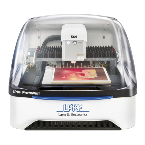
The ProtoMat S64/S104 is a circuit board plotter for structuring single-layer and multi- layer circuit boards. The tool magazine can accommodate up to 20 different drilling and milling tools (ProtoMat S104 only, 15 tools for ProtoMat S64) that can realize among others the following applications: ... -
Page 26: Scope Of Delivery
Structure and function ProtoMat S64/S104 Further characteristics of the system are: Milling spindle with a rotation speed of 60 000 rpm (ProtoMat S64) or 100 000 rpm (ProtoMat S104). Integrated camera for recognizing fiducials to enable processing multilayer PCBs. ... - Page 27 The following wear parts are excluded from the warranty: Foot of working-depth limiter (order code: 10075375) Filter pad for air intake (order code: 10031630) Tool holders (order code: 10057207) V. 1.0 | LPKF Laser & Electronics AG 27/160...
-
Page 28: Type Label
The type label is located at the housing of the system. For information on identifying the system and the relevant equipment, specify the system model and the serial number on the type label when you contact the LPKF Service. Fig. 3:... -
Page 29: System Components
3.4.1 Total view The following figures show the system and its components with closed and opened acoustic hood. Fig. 4: Front view with closed acoustic hood Acoustic hood Handle V. 1.0 | LPKF Laser & Electronics AG 29/160... - Page 30 Structure and function ProtoMat S64/S104 Fig. 5: Front view with opened acoustic hood Processing head Photo-interrupter Bellows x axis Tool magazine Processing table (vacuum) 30/160 LPKF Laser & Electronics AG | V. 1.0...
- Page 31 ProtoMat S64/S104 Structure and function Fig. 6: Side view right side Fig. 7: Rear view Fig. 8: Side view left side V. 1.0 | LPKF Laser & Electronics AG 31/160...
-
Page 32: Processing Head
Thus, even materials with sensitive surfaces can be processed without damage. The dispenser (4) applies solder paste at the designated positions of the PCB. 32/160 LPKF Laser & Electronics AG | V. 1.0... -
Page 33: Dispenser
You can manually adjust the amount of solder paste to be applied by using the pressure regulator of the processing head, if necessary. Fig. 11: Applying solder paste with the dispenser V. 1.0 | LPKF Laser & Electronics AG 33/160... -
Page 34: Camera
Measurement unit for determining the copper layer thickness Use this function to measure the thickness of the copper layer automatically. The measured value is applied for the copper layer thickness in the dialog Material settings. 34/160 LPKF Laser & Electronics AG | V. 1.0... -
Page 35: Processing Table
The processing table has an integrated station for contactless adjustment of the milling and drilling tools. Adjustment of the tools is controlled by the system software and runs automatically after picking up a tool. V. 1.0 | LPKF Laser & Electronics AG 35/160... -
Page 36: Tool Magazine
Tool magazine ProtoMat S104 (rear view) If you have a ProtoMat S64 you can buy an expansion of the tool magazine from 15 tools to 20 tools. Note that the installation of the tool holder kit and the configuration of the system has to be performed by the LPKF Service or your local representative. -
Page 37: Optional Modules, Accessories, Extras
Tool holder kit (order code: 10082398) Refer to the product catalog to find a list of all tools and optional modules available. For more information contact the LPKF sales department or your local representative. V. 1.0 | LPKF Laser & Electronics AG... -
Page 38: Extraction System
Structure and function ProtoMat S64/S104 3.5.1 Extraction system LPKF recommends using the JetStream iSeries AX079-25 extraction system. For a detailed description of the extraction system refer to the manufacturer's manual delivered with the extraction system. Fig. 18: Extraction system AX079-25... -
Page 39: Compressor
ProtoMat S64/S104 Structure and function 3.5.2 Compressor The compressor OF 750-24F-FM-1M is approved by LPKF and can be used for compressed-air production. WARNING Risk of injuries by pressurized components! Pressurized components (e.g. compressed-air supply) can move uncontrollably in case of improper handling or in case of a defect and can cause serious injuries. -
Page 40: Accessory Kits
ProtoMat S64/S104 3.5.3 Accessory kits The following accessory kits are available: Accessories kit ProtoMat S64 (order code: 10082407) Quantity Underlay Porex vacuum plate Base material FR4, 229 mm x 305 mm (9 x 12 in), 0/35 µm, thickness 1.5 mm, pre-drilled with 3 mm registration holes Base material FR4, 229 mm x 305 mm (9 x 12 in), 35/35 µm,... -
Page 41: Connections
ProtoMat S64/S104 Structure and function Accessories kit 2.5D ProtoMat S64/S104 (order code: 10086885) Quantity Base material Necuron 1300, 250 mm x 250 mm x 8 mm (~ 9.8 x 9.8 x 0.31 in) Base material Necuron 651, 300 mm x 250 mm x 8 mm (~ 11.8 x 9.8 x 0.31 in) -
Page 42: Pin Assignment
Property damage by a different extraction system! Extraction systems that are not approved by LPKF can cause system damage. Use extraction systems that are approved by LPKF in order to guarantee a safe use of the system and to avoid damage. -
Page 43: Displays And Control Elements
Not lit: The system is not ready for operation because it is switched off or a fault has occurred. The button is used to switch the vacuum of the processing V. 1.0 | LPKF Laser & Electronics AG 43/160... - Page 44 The pressure regulator for the dispenser (5) is at the processing head. It is used for regulating the amount of solder paste exiting the dispenser needle. Table 9: Displays and control elements 44/160 LPKF Laser & Electronics AG | V. 1.0...
-
Page 45: Software
The following system requirements have to be met in order to install CircuitPro PM successfully: Component Minimum system requirements 2 GHz LPKF discourages the use of the following CPU because it causes problems: Intel Xeon 2 GB Memory requirements... -
Page 46: Modes Of Operation
(operator and Advanced user) various setting options (for more information refer to the CircuitPro PM compendium). The service mode is activated by entering a password in the software and is reserved for the LPKF Service. 46/160 LPKF Laser & Electronics AG | V. 1.0... -
Page 47: Transport And Storage
(standby, switched off, transport, storage). Ensure that a tool is in the collet or a tool is in the tool magazine where it can be picked up by the collet. V. 1.0 | LPKF Laser & Electronics AG 47/160... -
Page 48: Transport Inspection
Observe the local disposal regulations and hire a specialized company for the disposal, if necessary. The system may only be shipped in the original packaging of LPKF. Contact the LPKF Service if you need the packaging. 48/160 LPKF Laser & Electronics AG | V. 1.0... -
Page 49: Symbols On The Packaging
Protect packages against moisture and keep them dry. Fragile Identifies packages with fragile or sensitive contents. Handle the package with care, do not drop, and do not subject it to shocks. V. 1.0 | LPKF Laser & Electronics AG 49/160... -
Page 50: Unpacking The System
The system weighs 95 kg (~209.4 lbs) and has to be lifted by four persons using the lifting device: Fig. 22: System with lifting device Foam damper Transport sling Steel rod 50/160 LPKF Laser & Electronics AG | V. 1.0... - Page 51 Unpacking the system 1. Cut the black polyester straps that secure the transport box using a safety cutter and remove them. Fig. 23: Polyester straps removed 2. Open the transport box. V. 1.0 | LPKF Laser & Electronics AG 51/160...
- Page 52 Transport and storage ProtoMat S64/S104 Fig. 24: Transport box opened 3. Remove the sheet of cardboard. Fig. 25: Removing the sheet of cardboard 4. Remove the two steel rods for lifting the system. 52/160 LPKF Laser & Electronics AG | V. 1.0...
- Page 53 ProtoMat S64/S104 Transport and storage Fig. 26: Removing the steel rods Fig. 27: Steel rods 5. With the help of another person, pull the transport box upwards. Put the transport box aside. V. 1.0 | LPKF Laser & Electronics AG 53/160...
- Page 54 Transport and storage ProtoMat S64/S104 Now, the padding material at the sides is accessible: Fig. 28: Padding material 6. Remove the padding material at the sides successively. 54/160 LPKF Laser & Electronics AG | V. 1.0...
- Page 55 Transport and storage Fig. 29: Removing the padding material on the left side Fig. 30: Removing the padding material on the right side Now, the system is accessible from both sides: V. 1.0 | LPKF Laser & Electronics AG 55/160...
- Page 56 7. Pull out the four transport slings of the system. Fig. 32: Transport sling pulled out 8. Push the steel rod through the foam damper and through both of the transport slings on the left side of the system. 56/160 LPKF Laser & Electronics AG | V. 1.0...
- Page 57 Always wear the recommended safety shoes and protective gloves. 10. Lift the system in a group of four, with each person holding one end of the rods. Fig. 34: System lifted by a group of four V. 1.0 | LPKF Laser & Electronics AG 57/160...
- Page 58 The system can be transported over short distances (e.g. within a room or a building) using a table trolley. Make sure that the table trolley has an appropriate load-bearing capacity. The system has been unpacked. 58/160 LPKF Laser & Electronics AG | V. 1.0...
- Page 59 1. Remove the foam pad beneath the processing head. Fig. 35: Transport lock 2. Store the foam pad in the box for a possible transport of the system. The transport lock has been removed. V. 1.0 | LPKF Laser & Electronics AG 59/160...
-
Page 60: Transporting The System
Always wear the recommended safety shoes and protective gloves when lifting the system. 2. Put the system down on a table trolley. Make sure that the table trolley has a sufficient load-bearing capacity! 60/160 LPKF Laser & Electronics AG | V. 1.0... -
Page 61: Storage
When putting the system out of operation and into storage over a longer period, ensure that the storage room is clean, almost dust-free, and has a sufficient loadbearing capacity. V. 1.0 | LPKF Laser & Electronics AG 61/160... -
Page 62: First Startup
When transporting or storing the system, moisture can cause damage to the system. Ensure that there is no moisture in the system. Before first startup of the system wait approx. 24 hours to allow the system to acclimatize. 62/160 LPKF Laser & Electronics AG | V. 1.0... -
Page 63: Requirements Of The Place Of Installation
(in) Height 560 (~22) mm (in) Minimum required space for operation and maintenance Data Value Unit Width 2200 (~86.6) mm (in) Depth 1400 (~55.1) mm (in) Height 750 (~29.5) mm (in) V. 1.0 | LPKF Laser & Electronics AG 63/160... - Page 64 In front of the system, at least 400 mm (15.8 in) of space should be available for operation and movement. Fig. 36: Minimum required space Extraction system PC (recommended position for desk and PC) System 64/160 LPKF Laser & Electronics AG | V. 1.0...
-
Page 65: Workplace Of The Operating Personnel
The system work station is used for loading and unloading the system. PC work station The PC work station is used for monitoring the production and for controlling the system. V. 1.0 | LPKF Laser & Electronics AG 65/160... -
Page 66: Floor
Ensure that the floor has a sufficient load-bearing capacity for the system and is even. 5.2.5 The system's center of gravity The following figure shows the center of gravity of the system: Fig. 38: Center of gravity of the system 66/160 LPKF Laser & Electronics AG | V. 1.0... -
Page 67: Connections Provided By The Customer
Pneumatic data Data Value Unit min. 6 Pressure Standard volume flow 40 l/min @ 6 bar Nl/min Compressed-air purity acc. to ISO 8573-1:2010-04 Data Value Unit Solid particles Class Water Class Class V. 1.0 | LPKF Laser & Electronics AG 67/160... -
Page 68: Preparations
ProtoMat S64/S104 Preparations Before the system is installed, you have to consider and ensure the following: A suitable extraction system has to be provided. LPKF recommends using the JetStream iSeries AX079-25 extraction system. This is optionally available at LPKF. ... -
Page 69: Connecting The Extraction System
Do not block the air flow. 5.4.1 Connecting the extraction system The extraction system is an optional accessory that can be ordered at LPKF. The following describes the required steps for connecting the JetStream iSeries AX079-25: Material The following material is required: Fig. - Page 70 Fig. 44: Extraction hose connected to the system 3. Connect the other end of the extraction hose with the extraction system. Fig. 45: Connecting the extraction hose 70/160 LPKF Laser & Electronics AG | V. 1.0...
- Page 71 The extraction system has been connected. LPKF recommends to set the extraction system to 70 %. You can adapt the run-down time of the extraction system according to your requirements. For further information refer to the user manual of the extraction system.
-
Page 72: Connecting The Compressed-Air Supply
1. Connect the pneumatic tube to the compressed-air connector G 1/4". Fig. 50: Connecting the pneumatic tube to the system 2. Connect the pneumatic tube with the compressed-air supply (maximum pressure: 6 bar). The compressed-air supply has been connected. 72/160 LPKF Laser & Electronics AG | V. 1.0... -
Page 73: Establishing A Connection Between The Camera And The Pc
2. Connect the A cable of the provided USB cable to the slot of the PC. Fig. 52: Connecting the USB cable for the camera Extending the USB cable can interfere with the camera image. The camera has been connected to the PC. V. 1.0 | LPKF Laser & Electronics AG 73/160... -
Page 74: Establishing A Connection Between The System And The Pc
Connecting the USB cable to the system 2. Connect the A cable of the provided USB cable to the slot of the PC. Extending the USB cable causes transmission problems. The maximum cable length is 3 meters. 74/160 LPKF Laser & Electronics AG | V. 1.0... -
Page 75: Connecting The System To The Mains Power Supply
1. Connect the mains cable to the system. 2. Connect the mains cable to the earthed wall socket. Ensure that the earthed wall socket is always accessible! The mains cable has been connected. V. 1.0 | LPKF Laser & Electronics AG 75/160... -
Page 76: Connecting The Pc To The Mains Power Supply
Once the system and the corresponding software are ready for operation, the dummy tool is ejected automatically when a processing job is started. Fig. 58: Dummy tool 76/160 LPKF Laser & Electronics AG | V. 1.0... -
Page 77: Software
The Equipment configuration wizard starts automatically at the first start of CircuitPro PM. If the wizard does not start automatically, click on Wizards > Equipment configuration wizard. For further information on the Equipment configuration wizard refer to the CircuitPro PM compendium. V. 1.0 | LPKF Laser & Electronics AG 77/160... -
Page 78: Operating The System
When the system is switched on items in the processing area can cause property damage. Before switching on the system, always ensure that no items and no parts are in the processing area. 78/160 LPKF Laser & Electronics AG | V. 1.0... - Page 79 Once you have stopped the system in an emergency you have to switch the system on again and reconnect it with the system software. The following message is displayed on your screen: Fig. 62: Message Connection lost V. 1.0 | LPKF Laser & Electronics AG 79/160...
-
Page 80: Preparations For Use
The following components have to be connected to the system and have to be ready for operation: PC (provided by customer) Extraction system Power supply Operate the system on an over-current protection (240 V / 16 A / 100 V). 80/160 LPKF Laser & Electronics AG | V. 1.0... -
Page 81: Typical Production Process
Switching on the system and the components 1. Start the PC. 2. Start the extraction system. 3. Switch the On/Off switch of the system to position I. The system and the components have been switched on. V. 1.0 | LPKF Laser & Electronics AG 81/160... - Page 82 Operating the system ProtoMat S64/S104 Starting CircuitPro PM 1. Click on the desktop link or on Start > (All) Programs > LPKF Laser & Electronics > CircuitPro PM. The following dialog is displayed: Fig. 63: Dialog New document 4.
- Page 83 Once the system has been recognized and its data have been transmitted, the user interface of CircuitPro PM is displayed. The PC has been connected to the system. V. 1.0 | LPKF Laser & Electronics AG 83/160...
-
Page 84: Preparing The Data
The following dialog is displayed: Fig. 67: Importing data 2. Navigate to the following folder: Win 7 to Win 10: C:\Program Files (x86)\LPKF Laser & Electronics\LPKF CircuitPro PM 2.x\Example Data\UseCase_DoubleSidedPCB 3. Select all files in the folder. 4. Click on [Open]. - Page 85 Layer/Template. 6. Click on [OK]. The CAM view changes as follows: Fig. 69: Layout data in the CAM view The data have been imported. V. 1.0 | LPKF Laser & Electronics AG 85/160...
- Page 86 The presentation of the objects on the individual layers can be defined in the pane Layers. 3. Click on [Close]. The rubout area has been created. 86/160 LPKF Laser & Electronics AG | V. 1.0...
- Page 87 6. Click on [Apply]. The layout is copied in x direction: Fig. 73: Layout copied in x direction 7. Click on [Close]. The dialog is closed. The layout has been multiplied. V. 1.0 | LPKF Laser & Electronics AG 87/160...
- Page 88 Create the fiducials by entering the x and y position in the dialog. The view changes as follows: Fig. 75: Fiducials created 4. Click on [Close]. The fiducials have been created. 88/160 LPKF Laser & Electronics AG | V. 1.0...
- Page 89 2. Click on the right arrow button in the group Isolate until the Isolation Method Partial rubout is displayed. 3. Deactivate the function Pockets by clicking on the corresponding check mark. 4. Click on [Start]. V. 1.0 | LPKF Laser & Electronics AG 89/160...
- Page 90 You can also deactivate tools that are not available in the Technology dialog using Show details so that these are not used for toolpath generation. 6. Click on [Close]. 90/160 LPKF Laser & Electronics AG | V. 1.0...
- Page 91 ProtoMat S64/S104 Operating the system The dialog with the computation results is closed and the CAM view changes as follows: Fig. 78: Generated toolpaths The toolpaths have been generated. V. 1.0 | LPKF Laser & Electronics AG 91/160...
- Page 92 The following dialog is displayed: Fig. 79: Tool magazine The tools required for circuit board production are displayed. Tools that are missing in the tool magazine are marked with a red X. 92/160 LPKF Laser & Electronics AG | V. 1.0...
- Page 93 4. Insert the tools into the tool holders of the tool magazine. Ensure that the tools are inserted into the tool holder positions that you have assigned in the dialog Tool magazine! V. 1.0 | LPKF Laser & Electronics AG 93/160...
- Page 94 Inserting tools 5. Click on [OK]. The dialog is closed. The tools are in their holder positions. Fig. 83: Loaded tool magazine (example) The tool magazine has been loaded. 94/160 LPKF Laser & Electronics AG | V. 1.0...
-
Page 95: Processing The Material
Health hazard by gases or dusts! Processing materials can produce gases or dusts hazardous to health. Process only materials that are approved by LPKF. Only work with an extraction system that is switched on and is working properly. - Page 96 Material fastened The adhesive tape must be fully removable. Use the provided adhesive tape or an equivalent adhesive tape. The material has been placed and fastened on the processing table. 96/160 LPKF Laser & Electronics AG | V. 1.0...
- Page 97 Once you have started processing, the system processes the job in different phases. These phases are displayed as messages. Depending on the system used, the displayed messages and phases can differ from the following. Follow the instructions on your screen. V. 1.0 | LPKF Laser & Electronics AG 97/160...
- Page 98 5. For defining the material area, move the dialog Material settings to the side. 6. In the Machining view click on the position of the screen that represents the right rear corner of your material: 98/160 LPKF Laser & Electronics AG | V. 1.0...
- Page 99 8. Click on [P1]in the dialog Material settings. The material area is adapted to the material. 9. Click on [OK]. The phase Placement is started. The material settings have been defined. V. 1.0 | LPKF Laser & Electronics AG 99/160...
- Page 100 5. Click on [Apply]. The layout is copied in y direction. 6. Click on [Continue]. The phase DrillFiducial is started. The layout has been placed. 100/160 LPKF Laser & Electronics AG | V. 1.0...
- Page 101 The Top side has thus been aligned to the Bottom side. The following dialog is displayed, if the fiducials are not found automatically: V. 1.0 | LPKF Laser & Electronics AG 101/160...
- Page 102 ContourRouting: The processing head picks up various drilling and milling tools to drill holes and cut the contour. BoardProductionFinish: A message informs you that the production of the printed circuit board is finished. 102/160 LPKF Laser & Electronics AG | V. 1.0...
-
Page 103: Switching Off The System
2. Use the On/Off switch to switch off the system. 3. Switch off the extraction system by pressing the Power button. The system has been switched off. V. 1.0 | LPKF Laser & Electronics AG 103/160... -
Page 104: Special Tasks
4. Tighten the screw of the cleaning device with the wrench Torx 10. The cleaning device is inserted. Fig. 92: Cleaning device inserted 5. In the system software click on Edit > Tool magazine. 104/160 LPKF Laser & Electronics AG | V. 1.0... - Page 105 Ensure that the tool holder position indicated in the dialog Tool magazine corresponds to the actual tool holder position on the processing table. 7. Click on [OK]. The dialog is closed. The cleaning device has been inserted. V. 1.0 | LPKF Laser & Electronics AG 105/160...
- Page 106 5. Click on [Save] to apply the measured value in the dialog Material settings. The thickness of the copper layer has been measured. 106/160 LPKF Laser & Electronics AG | V. 1.0...
- Page 107 The material thickness is measured at the current position of the processing head by default. If necessary, move the processing head to a different position where you want to measure the thickness of the material using the arrow buttons in the pane Processing. V. 1.0 | LPKF Laser & Electronics AG 107/160...
- Page 108 4. Click on [Save] to apply the measured value in the dialog Material settings. The thickness of the material has been measured. 108/160 LPKF Laser & Electronics AG | V. 1.0...
- Page 109 Dispenser cartridge with solder paste and milled) (room temperature) In order to apply the solder paste evenly, LPKF recommends the use of the honeycomb plate (order code: 116 148) 1. Click on File > New... 2. In the tab Templates select the template DoubleSided_NoTHP.cbf.
- Page 110 Layer/Template. 8. Click on [OK]. The CAM view changes as follows: Fig. 101: CAM view 9. Click on Toolpath > Technology dialog. 110/160 LPKF Laser & Electronics AG | V. 1.0...
- Page 111 Fig. 102: Dialog Technology dialog 10. Click on [Start]. The toolpaths are generated. The CAM view changes as follows: Fig. 103: CAM view with toolpaths 11. Click on Toolpath > Solder paste... V. 1.0 | LPKF Laser & Electronics AG 111/160...
- Page 112 This is realized with the help of different parameter sets. All dispenser tools use the same dispenser as well as the same dispenser needle. Table 14: Settings in the dialog Dispense 12. Click on [Start]. 112/160 LPKF Laser & Electronics AG | V. 1.0...
- Page 113 The dispenser toolpaths are generated. 14. Click on Wizards > Dispense Wizard… The following dialog is displayed: Fig. 106: Preparing the dispenser 15. Follow the instructions in the dialog and subsequently click on [Next]. V. 1.0 | LPKF Laser & Electronics AG 113/160...
- Page 114 Fig. 108: Measuring the thickness of the material 17. Click on [Measure]. The material thickness is automatically measured with the working-depth limiter. The measured value is displayed in the dialog. 18. Click on [Next]. 114/160 LPKF Laser & Electronics AG | V. 1.0...
- Page 115 This area should be outside of your actual PCB so solder paste that might escape does not reduce the quality of your PCB. 20. Click on [Next]. V. 1.0 | LPKF Laser & Electronics AG 115/160...
- Page 116 Fig. 111: Determining the position of the auxiliary board 21. Click on any position to determine the area of the auxiliary board. Fig. 112: Dialog Position of auxiliary board area 22. Click on [Next]. 116/160 LPKF Laser & Electronics AG | V. 1.0...
- Page 117 23. Follow the instructions in the dialog and subsequently click on [Next]. The following dialog is displayed: Fig. 114: Determining the height of the dispenser tip 24. Follow the instructions in the dialog and subsequently click on [Next]. V. 1.0 | LPKF Laser & Electronics AG 117/160...
- Page 118 If the camera cannot detect a solder paste dot, the spiral search is started (for further information refer to the CircuitPro PM compendium). The following dialog is displayed: Fig. 116: Selecting the drill hole 26. Click on [Next]. 118/160 LPKF Laser & Electronics AG | V. 1.0...
- Page 119 Make sure that the mouse cursor (arrow) is activated. Fig. 117: Drill hole selected The following dialog is displayed: Fig. 118: Selecting the opposite drill hole 28. Click on [Next]. V. 1.0 | LPKF Laser & Electronics AG 119/160...
- Page 120 29. In the machining view click on the opposite drill hole. Make sure that the mouse cursor (arrow) is activated. Fig. 119: Opposite drill hole selected The following dialog is displayed: Fig. 120: Performing the dispensing procedure 120/160 LPKF Laser & Electronics AG | V. 1.0...
- Page 121 The dispensing procedure is started. The progress bar indicates the processing status. As soon as the dispensing procedure is completed, the view changes as follows: Fig. 121: Dispensing procedure completed The solder paste has been applied to the PCB. V. 1.0 | LPKF Laser & Electronics AG 121/160...
-
Page 122: Maintenance
Contact the LPKF Service for maintenance or repair tasks that go beyond the tasks described in the maintenance schedule for the maintenance personnel of the operator. - Page 123 4. Switch on the system (On/Off switch in position I) and start the system system software. The connection is established automatically and the system moves to its reference points. The system has been restarted after an emergency. V. 1.0 | LPKF Laser & Electronics AG 123/160...
-
Page 124: Personal Protective Equipment
Replacing the filter bag See page 141. weakens noticeably. HEPA filter of the After 1000 operating hours Replacing See page 143. extraction system Table 15: Maintenance schedule for the maintenance personnel of the operator 124/160 LPKF Laser & Electronics AG | V. 1.0... -
Page 125: Maintenance Tasks For The Maintenance Personnel Of The Operator
3. Check the processing head and the processing table for visible damage. If you find damage: Ensure that the system cannot be used. Contact the LPKF Service. The visual check is concluded. V. 1.0 | LPKF Laser & Electronics AG 125/160... - Page 126 1. Disconnect the mains plug from the wall socket. 2. Remove material residues from the processing table using a soft brush and a dry antistatic cloth (e.g. microfiber cloth): Fig. 125: Cleaning the interior of the system 126/160 LPKF Laser & Electronics AG | V. 1.0...
- Page 127 Fig. 126: Cleaning the interior with a vacuum cleaner 4. Wipe the cover with a slightly damp cloth: Fig. 127: Cleaning the cover 5. Connect the mains plug to the wall socket. The system has been cleaned. V. 1.0 | LPKF Laser & Electronics AG 127/160...
- Page 128 CircuitPro PM while performing maintenance tasks on the collet. 4. Open the cover. 5. Insert the collet wrench (2) into the collet opening (1): Fig. 128: Collet wrench inserted Collet opening Collet wrench 128/160 LPKF Laser & Electronics AG | V. 1.0...
- Page 129 Fig. 129: Removing the collet 8. Clean the collet fixture with the cleaning cone: Fig. 130: Cleaning the collet fixture 9. Clean the collet from the inside and the outside with the cylindrical brush: V. 1.0 | LPKF Laser & Electronics AG 129/160...
- Page 130 13. Turn the collet wrench clockwise until the collet sits hand-tight in the collet fixture. 14. Remove the maintenance materials from the system and close the cover. The collet has been cleaned and lubricated. 130/160 LPKF Laser & Electronics AG | V. 1.0...
- Page 131 Fig. 133: Cleaning the working-depth limiter with brush Cleaning is finished. 5. For replacing the working-depth limiter, remove the five screws with the wrench: V. 1.0 | LPKF Laser & Electronics AG 131/160...
- Page 132 7. Insert the new working-depth limiter. 8. Tighten the screws with the wrench. 9. Remove the maintenance materials from the system and close the cover. The working-depth limiter has been cleaned/replaced. 132/160 LPKF Laser & Electronics AG | V. 1.0...
- Page 133 3. Push the bellows of the x axis to the right: Fig. 136: Pushing the bellows to the right 4. Clean the linear guides and the drive spindle with a cotton cloth: V. 1.0 | LPKF Laser & Electronics AG 133/160...
- Page 134 Fig. 141: Applying precision mechanics oil Fig. 142: Lubricating the linear guides 7. Push the bellows of the x axis back into position. 8. Push the bellows of the y axis aside: 134/160 LPKF Laser & Electronics AG | V. 1.0...
- Page 135 10. Push the bellows of the y axis back into position. 11. Close the cover. 12. Move the processing head to the zero position. 13. Open the cover: Fig. 144: Moving the processing head to the zero position V. 1.0 | LPKF Laser & Electronics AG 135/160...
- Page 136 4 to 6. 19. Remove the maintenance materials from the system and close the cover. The drive spindle and the linear guides have been cleaned and lubricated. 136/160 LPKF Laser & Electronics AG | V. 1.0...
- Page 137 7. Dispose of the old filter mat according to the local disposal regulations. 8. Remove the maintenance materials from the system and close the cover. The fan filter has been replaced. V. 1.0 | LPKF Laser & Electronics AG 137/160...
- Page 138 Fig. 150: Opening the drain valve 4. Wait until the condensate trap is completely empty. 5. Turn the drain valve clockwise until it is fastened hand-tight. The condensate has been drained from the compressed-air unit. 138/160 LPKF Laser & Electronics AG | V. 1.0...
- Page 139 Fuse (250 VAC; T6.3 A; 20 x 5 mm; according to EN 60127-2-3) Fig. 151: Fuse holder 1. Disconnect the mains cable from the power supply. 2. Use a flat-bladed screwdriver to pull out the fuse holder. V. 1.0 | LPKF Laser & Electronics AG 139/160...
- Page 140 5. Reinsert the fuse holder containing the new fuse. 6. Push in the fuse holder completely. 7. Reconnect the mains cable to the power supply. 8. Switch on the system. The fuse has been replaced. 140/160 LPKF Laser & Electronics AG | V. 1.0...
- Page 141 2. Remove the side cover (3). The filter bag is visible. 3. Remove the filter bag from the air inlet. 4. Fasten the new filter bag to the air inlet on the inside. V. 1.0 | LPKF Laser & Electronics AG 141/160...
- Page 142 Fig. 155: Interior view without filter bag Air inlet Protective grille 5. Fasten the side cover. 6. Fasten the knob screws on the side cover. The filter bag has been replaced. 142/160 LPKF Laser & Electronics AG | V. 1.0...
- Page 143 11. Fasten the knob screws on the side cover. 12. If the light Service Filters is still blinking or is constantly lit, reset the filter alarm. The HEPA filter has been replaced. V. 1.0 | LPKF Laser & Electronics AG 143/160...
-
Page 144: Troubleshooting
If faults occur that cannot be eliminated by the following messages contact the LPKF Service. Furthermore, you can create a support information (only S104) via the menu Machining and send it via e-mail to the LPKF Service. Fault display The system's Stack light/Status LED indicates occurring faults. In the software, faults are indicated via the panes Fault monitor and Messages. - Page 145 Warnings are due to input errors that the user has caused. For example, these can be information on aborted or improperly executed actions. The warnings can be displayed or hidden by clicking on [Warnings]. V. 1.0 | LPKF Laser & Electronics AG 145/160...
-
Page 146: Actions In Case Of An Error
Table 18: Pane Messages Actions in case of an error If a malfunction has occurred, you can contact the LPKF Service. You can create a support information (only S104) via the menu Machining so that the service technician can help you quickly. This zip file generated by the system contains, among others, the occurred malfunctions and error codes. -
Page 147: Fault Table
Selection of the user Change the user group to: Advanced user Grayed out function in group. the system software Insufficient PC Use a suitable PC. Error message: resources. System resources V. 1.0 | LPKF Laser & Electronics AG 147/160... - Page 148 No cleaning device Use the cleaning device (see page 104. Drilling tool heavily used. soiled Unsuitable drilling Correct the drilling parameters. parameters e.g. for custom tools. 148/160 LPKF Laser & Electronics AG | V. 1.0...
- Page 149 End Mill long. drill through the material despite correct material settings. Tool is damaged. Replace the tool. Milling-depth Tool is worn. adjustment for conical tools not possible Table 19: Fault table V. 1.0 | LPKF Laser & Electronics AG 149/160...
-
Page 150: Disassembly And Disposal
NOTICE Environmental hazard by improper disposal of the system! Improper disposal of the system can cause hazards to the environment. Dispose of the system properly or contact the LPKF Service. 150/160 LPKF Laser & Electronics AG | V. 1.0... -
Page 151: Preparations
Disposing of the system LPKF AG will accept a delivered product for which a manufacturer's obligation to take back is based on the Waste Electrical and Electronic Equipment directive and will dispose of it according to regulations. Contact the LPKF Service for more information on returning the system. -
Page 152: 10 Appendix
Measurement unit for determining the copper layer thickness ....34 Fig. 14: Processing table ..................35 Fig. 15: Tool magazine ProtoMat S64 (rear view) ........... 36 Fig. 16: Tool magazine ProtoMat S104 (rear view) ..........36 Fig. 17: Cleaning device ..................36 Fig. - Page 153 Fig. 105: CAM view after calculating the dispenser toolpaths ......... 113 Fig. 106: Preparing the dispenser ................113 Fig. 107: Placing the PCB ..................114 Fig. 108: Measuring the thickness of the material ........... 114 V. 1.0 | LPKF Laser & Electronics AG 153/160...
- Page 154 Fig. 156: Interior view without filter bag ..............143 Fig. 157: Fault monitor pane..................144 Fig. 158: Pane Messages ..................145 Fig. 159: Declaration of conformity (German) ............157 Fig. 160: Declaration of conformity (English) ............158 154/160 LPKF Laser & Electronics AG | V. 1.0...
-
Page 155: 10.2 List Of Tables
Table 4: Accessories kit S64 ..................40 Table 5: Accessories kit S104 .................. 40 Table 6: Accessories kit 2.5D ProtoMat S64/S104 ..........41 Table 7: Starter kit 2.5D ProtoMat S64/S104 ............41 Table 8: Pin assignment D-sub 25-pin ..............42 Table 9: Displays and control elements .............. -
Page 156: 10.3 Index
....81 packaging Typical production process ....81 symbols on the packaging .... 49 unpacking the system ....50 pneumatic data ......23, 67 process data ........24 warranty ..........7 156/160 LPKF Laser & Electronics AG | V. 1.0... -
Page 157: 10.4 Ec Declaration Of Conformity
ProtoMat S64/S104 Appendix 10.4 EC Declaration of conformity Fig. 159: Declaration of conformity (German) V. 1.0 | LPKF Laser & Electronics AG 157/160... - Page 158 Appendix ProtoMat S64/S104 Fig. 160: Declaration of conformity (English) 158/160 LPKF Laser & Electronics AG | V. 1.0...
Need help?
Do you have a question about the ProtoMat S64 and is the answer not in the manual?
Questions and answers