Table of Contents
Advertisement
Quick Links
Advertisement
Table of Contents

Related Manuals for Ozito DP-350


Summary of Contents for Ozito DP-350
-
Page 2: Specifications
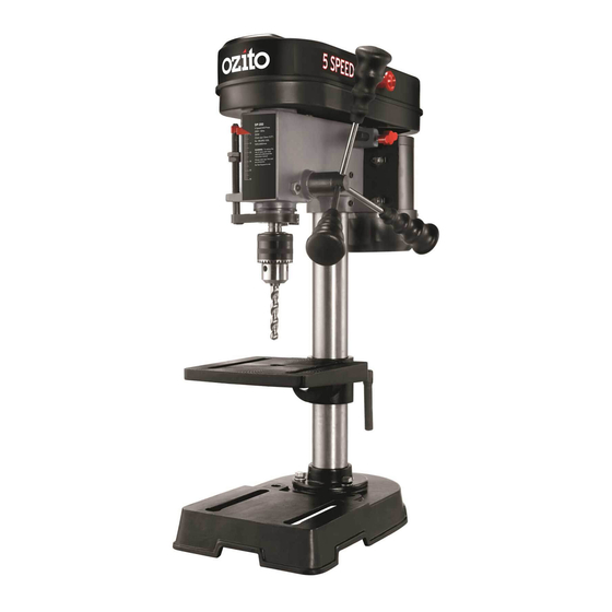
SPECIFICATIONS – MODEL NO. DP-350 Motor size: 350W Input: 230-240V ~ 50Hz No load speed: 580, 850, 1220, 1650, 2650/min Chuck: 13mm Keyed Spindle travel: 50mm Spindle shaft to column distance: 104mm Column height: 395mm Protection class: 1 (Earthed Appliance) Weight: 16.4kg... -
Page 3: Table Of Contents
TABLE OF CONTENTS SPECIFICATIONS………………………………………… Page 1 INTRODUCTION………………………………………... Page 3 ELECTRICAL SAFETY…………………………………... Page 3 GENERAL SAFETY INSTRUCTIONS………………….. Page 4 DRILL PRESS SAFETY WARNINGS …………………… Page 6 ASSEMBLY……………………………………………….. Page 8 ADJUSTMENTS…………………………………………. Page 10 OPERATION………………………………………….….. Page 12 MAINTENANCE…………………………………………. Page 12 SPARE PARTS……………………………………………. Page 13 TROUBLESHOOTING………………………………….. -
Page 4: Introduction
The electric motor has been designed for 230V and 240V only. Always check that the power supply corresponds to the voltage on the rating plate. Note: The supply of 230V and 240V on Ozito tools are interchangeable for Australia and New Zealand. -
Page 5: General Safety Instructions
GENERAL SAFETY INSTRUCTIONS WARNING! Read all instructions. Failure to follow all instructions listed below may result in electric shock, fire and/or serious injury. The term “Power Tool” in all of the warnings listed below refers to your mains operated (corded) power tool or battery operated (cordless) power tool. SAVE THESE INSTRUCTIONS 1) WORK AREA a) Keep work area clean and well lit. - Page 6 GENERAL SAFETY INSTRUCTIONS (cont.) Dress properly. Do not wear loose clothing or jewellery. Keep your hair, clothing and gloves away from moving parts. Loose clothes, jewellery or long hair can be caught in moving parts. g) If devices are provided for the connection of dust extraction and collection facilities, ensure these are connected and properly used.
-
Page 7: Drill Press Safety Warnings
DRILL PRESS SAFETY WARNINGS WARNING! For your own safety, do not try to use your drill press or plug it in until it is completely assembled and installed according to the instructions and until you have read and understood the following: 1. - Page 8 DRILL PRESS SAFETY WARNINGS 21. Do not perform layout assembly or setup work on the table while the drill press is in operation. 22. Do not exceed the rpm stated on the bit or accessory. See the instructions that come with the accessory. 23.
-
Page 9: Assembly
ASSEMBLY WARNING! During assembly ensure the drill press is disconnected from the power supply. 1. Carefully remove contents from the packaging. 2. Select a firm, level surface on which to assemble the drill press. 3. Select the base (10) (Fig. 1) and align the column (8) over the large hole (Fig. 2). Align the holes in the column support (9) with those in the base (10) and secure in place using the 3 column support bolts (19), spring and flat washers (supplied) (Fig. - Page 10 ASSEMBLY (cont.) 6. To fit the feed wheel handles (6), screw them into the feed wheel hub (5) (Fig. 6 & 7). Fig. 7 Fig. 6 7. To fit the 13mm keyed chuck (18), first place a piece of timber on the table (11) and position the 13mm keyed chuck (18) with the jaws retracted under the drive shaft.
-
Page 11: Adjustments
ADJUSTMENTS WARNING! Before making any adjustments, ensure the drill press is disconnected from the mains power. Adjusting the Table Height 1. Loosen the table support lock (23) (Fig. 14). 2. Set the desired table height and tighten the table support lock (23) to secure the table (11) in position (Fig. - Page 12 ADJUSTMENTS (cont.) 3. Whilst holding the feed wheel handles (6), tighten the depth indicator lock nuts (15) until they touch the metal stop (Fig. 21). 4. Lift the feed wheel handles up and then proceed to operate the drill press. 5.
-
Page 13: Operation
3mm allen key (20) provided. Loosen in Fig. 26 an anti-clockwise direction (Fig. 26). Note: Ozito Industries will not be responsible for any damage or injuries caused by the repair of the drill press by an unauthorised person or by mishandling of the drill press. -
Page 14: Spare Parts
SPARE PARTS Limited spare parts are available subject to availability. Please contact your local Bunnings Special Orders Desk to order the required spare parts. Most common spare parts listed below Spare Part Part No. Handle Sleeve SPDP350-16 Switch SPDP350-50 Drive Belt SPDP350-67 TROUBLESHOOTING Problem... -
Page 15: Description Of Symbols
3 x Column support bolts 1 x Table 1 x 4mm Allen key 1 x Instruction manual OZITO INDUSTRIES PTY LTD AUSTRALIA (Head Office) 1-23 Letcon Drive, Bangholme Victoria, Australia, 3175 Telephone: 1800 069 486 Facsimile: +61 3 9238 5588 Website: www.ozito.com.au... -
Page 16: Warranty
If the tool shows signs of damage or defects caused by or resulting from abuse, accidents • or alterations. • Failure to perform maintenance as set out within the instruction manual. • If the tool is disassembled or tampered with in any way. OZITO Australia/New Zealand (Head Office) 1-23 Letcon Drive, Bangholme, Victoria, Australia 3175...
Need help?
Do you have a question about the DP-350 and is the answer not in the manual?
Questions and answers